 Open Access Article
Creative Commons Attribution 3.0 Unported Licence
Magnetically-actuated artificial cilium: a simple theoretical model†
Fanlong
Meng
 ab,
Daiki
Matsunaga
ac,
Julia M.
Yeomans
a and
Ramin
Golestanian
 *ab
*ab
aRudolf Peierls Centre for Theoretical Physics, University of Oxford, Oxford OX1 3PU, UK. E-mail: ramin.golestanian@ds.mpg.de
bMax Planck Institute for Dynamics and Self-Organization (MPIDS), 37077 Göttingen, Germany
cGraduate School of Engineering Science, Osaka University, 5608531 Osaka, Japan
First published on 19th March 2019
Abstract
We propose a theoretical model for a magnetically-actuated artificial cilium in a fluid environment and investigate its dynamical behaviour, using both analytical calculations and numerical simulations. The cilium consists of a spherical soft magnet, a spherical hard magnet, and an elastic spring that connects the two magnetic components. Under a rotating magnetic field, the cilium exhibits a transition from phase-locking at low frequencies to phase-slipping at higher frequencies. We study the dynamics of the magnetic cilium in the vicinity of a wall by incorporating its hydrodynamic influence, and examine the efficiency of the actuated cilium in pumping viscous fluids. This cilium model can be helpful in a variety of applications such as transport and mixing of viscous solutions at small scales and fabricating microswimmers.
1 Introduction
Motile cilia, frequently observed on the surfaces of microorganisms1,2 and in mammalian tubes,3,4 constitute an important class of bio-machines at the micro/nano-scales. Each biological cilium usually consists of bio-motors as the actuator and an elastic axoneme, and cilia can achieve various functions by beating, for example, liquid transportation such as mucus removal in animal tracheas and self-propulsion of microorganisms.Corresponding to these natural examples, fabrication of artificial cilia,5–10 especially magnetic ones, has received increasing attention in the past ten years. They have been applied for fluid transport,11–16 as flagella of microswimmers,17–20 as solution stirrers,21,22 or as micromechanical sensors.23 Magnetic cilia are always actuated by an external magnetic field, and their filaments can be fabricated in various forms. Currently in experiments, there are two popular filament designs: superparamagnetic chained beads or rods,5,11–15,17,18,23,24 and ferromagnetic rods or plates.16,19–22,25 These two types of filaments present different challenges: for example, the complexity in the magnetic dipole–dipole interaction in superparamagnetic chained beads or rods renders analytical predictions and precise control difficult; ferromagnetic rods or plates are usually fabricated with rigid materials, which are less tunable than natural cilia, which consist of elastic filaments. Most of the existing theoretical analyses of the above-mentioned experiments with magnetic artificial cilia are numerical6,11,26 or phenomenological,13,24 and a simple theoretical model that incorporates the key ingredients and provides an intuitive understanding of how a magnetic cilium would behave under an external magnetic field is still lacking.
In the beating cycle of a cilium, there is usually a power stroke for generating flow and a recovery stroke bringing back the cilium to its starting configuration. As a result, the cilium moves in a quasi-circular trajectory, rather than performing a 1D oscillation. This acts as an essential element for pumping fluids, and by calculating the flow field induced by the force acting on the cilium in the vicinity of a substrate, one can study how the beating pattern determines the pump performance of a cilium.27–29 Moreover, cilia of different microorganisms beat with different patterns, and it is of interest to determine how this influences their swimming trajectories.30–33 However, the complexity in the irregular trajectories of natural cilia makes them difficult to replicate in artificial fabrications, and the absence of external control renders limitation in applications.
A microswimmer can be used as a cilium by pinning its head or tail. Inspired by this idea, and a magnetic microswimmer proposed by Ogrin et al.,34,35 we propose a model of a magnetic cilium based on the microswimmer model. This consists of a soft magnet sphere (with a magnetic moment of fixed magnitude and a direction following the magnetic field), a hard magnet sphere (with a magnetic moment of both fixed amplitude and direction, i.e. a permanent magnet in its body frame), and a connecting elastic spring. Very importantly, this simple model is more amenable to analytical treatment than other cilium models. Besides the fact that the motion of the cilium can be controlled by an external magnetic field, the existence of the magnetic dipole–dipole interaction between the hard and the soft magnets, and the elastic spring can make it promising to tune and optimize the pump performance of such a cilium.
Therefore, here we will study how such a system consisting of a soft magnet, a hard magnet and an elastic spring connecting the two spheres (shortened as a ‘soft-hard’ magnetic cilium) responds to an external magnetic field. We will consider its kinetic modes without a wall and its pump performance for fluid transport when it is attached to a wall.
2 Dynamics of the simple magnetic cilium
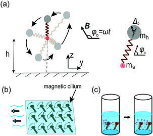
The model cilium is shown in Fig. 1(a). It consists of a soft magnet bead of radius rs, a hard magnet bead of radius rh, and an elastic spring of equilibrium length![[small script l]](https://www.rsc.org/images/entities/char_e146.gif) 0 and spring constant k; the elastic spring connects the two magnetic spheres. The position of the soft magnet is fixed (although it is free to rotate), and rs = 0 for simplicity. The magnetization of the soft magnet relaxes to the equilibrium orientation as defined by the external magnetic field on a time scale that is considerably shorter than the other relevant time scales in the system. For simplicity, we will only consider the stretch and the compression of the elastic spring, rather than other deformation modes such as bending or twisting.
0 and spring constant k; the elastic spring connects the two magnetic spheres. The position of the soft magnet is fixed (although it is free to rotate), and rs = 0 for simplicity. The magnetization of the soft magnet relaxes to the equilibrium orientation as defined by the external magnetic field on a time scale that is considerably shorter than the other relevant time scales in the system. For simplicity, we will only consider the stretch and the compression of the elastic spring, rather than other deformation modes such as bending or twisting.
Therefore, we assume that the magnetic moment of the soft magnet, denoted as ms, has a fixed ms, and its direction follows the external magnetic field (similar to paramagnetic materials). The hard magnet is treated as a permanent ferromagnet, and thus its magnetic moment, mh, has fixed amplitude and direction in its body frame. In an external magnetic field B whose direction does not match that of mh, then there will be a magnetic torque acting on the hard magnet. In this case, the cilium will rotate with the magnetic field. Note that there is no torque acting on the soft magnet. Such magnetism-elasticity coupling is also applied in many swimmer designs.36–39
Consider an actuation protocol in the form of an external magnetic field B that is rotating counterclockwise in the y–z plane [shown in Fig. 1(a)], with angular velocity ω and amplitude B, i.e., B = B(0,cos![[thin space (1/6-em)]](https://www.rsc.org/images/entities/char_2009.gif) ϕb,sin
ϕb,sin![[thin space (1/6-em)]](https://www.rsc.org/images/entities/char_2009.gif) ϕb) where ϕb(t) = ωt. We set the origin to be the location of the pinned point (i.e. the centre of the soft magnet sphere). Denoting the angle between the main axis of the cilium and the y axis as ϕc(t), and the length of the spring as
ϕb) where ϕb(t) = ωt. We set the origin to be the location of the pinned point (i.e. the centre of the soft magnet sphere). Denoting the angle between the main axis of the cilium and the y axis as ϕc(t), and the length of the spring as ![[small script l]](https://www.rsc.org/images/entities/char_e146.gif) (t), the location of the hard magnet sphere is given as (
(t), the location of the hard magnet sphere is given as (![[small script l]](https://www.rsc.org/images/entities/char_e146.gif) + rh)(0,cos
+ rh)(0,cos![[thin space (1/6-em)]](https://www.rsc.org/images/entities/char_2009.gif) ϕc,sin
ϕc,sin![[thin space (1/6-em)]](https://www.rsc.org/images/entities/char_2009.gif) ϕc). We define the radial unit vector along the direction of the cilium, er = (0,cos
ϕc). We define the radial unit vector along the direction of the cilium, er = (0,cos![[thin space (1/6-em)]](https://www.rsc.org/images/entities/char_2009.gif) ϕc,sin
ϕc,sin![[thin space (1/6-em)]](https://www.rsc.org/images/entities/char_2009.gif) ϕc), and the tangential unit vector, eϕ = (0,−sin
ϕc), and the tangential unit vector, eϕ = (0,−sin![[thin space (1/6-em)]](https://www.rsc.org/images/entities/char_2009.gif) ϕc,cos
ϕc,cos![[thin space (1/6-em)]](https://www.rsc.org/images/entities/char_2009.gif) ϕc), in the perpendicular direction.
ϕc), in the perpendicular direction.
Let us assume that there is a fixed angle, Δ0, between mh and er, i.e., the magnetic moment of the hard magnet sphere is: mh = mh(0,cos(ϕc + Δ0),sin(ϕc + Δ0)). The magnetic moment of the soft magnet sphere is ms = ms(0,cos![[thin space (1/6-em)]](https://www.rsc.org/images/entities/char_2009.gif) ϕb,sin
ϕb,sin![[thin space (1/6-em)]](https://www.rsc.org/images/entities/char_2009.gif) ϕb), as its direction always follows that of the magnetic field. We assume that the magnetic field induced by the hard magnet sphere at the location of the soft magnet sphere is much weaker than the external magnetic field, namely μ0mh/
ϕb), as its direction always follows that of the magnetic field. We assume that the magnetic field induced by the hard magnet sphere at the location of the soft magnet sphere is much weaker than the external magnetic field, namely μ0mh/![[small script l]](https://www.rsc.org/images/entities/char_e146.gif) 03 ≪ B, where μ0 is the magnetic permeability of a vacuum. By assuming the magnetic moments are point-like and located at the centre of each sphere for simplicity, we can write the following expression for the energy of the magnetic cilium, taking into account the elastic and magnetic contributions
03 ≪ B, where μ0 is the magnetic permeability of a vacuum. By assuming the magnetic moments are point-like and located at the centre of each sphere for simplicity, we can write the following expression for the energy of the magnetic cilium, taking into account the elastic and magnetic contributions
 | (1) |
 | (2) |
![[small script l]](https://www.rsc.org/images/entities/char_e146.gif) 02/(mhB) and Γ = μ0ms/(4π
02/(mhB) and Γ = μ0ms/(4π![[small script l]](https://www.rsc.org/images/entities/char_e146.gif) 03B), as
03B), as | (3) |
Using the energy expression, we can calculate the forces acting on the hard magnet along the radial and the tangential directions, as
 | (4) |
 | (5) |
 | (6) |
(![[small script l]](https://www.rsc.org/images/entities/char_e146.gif) + rh) + rh)![[small phi, Greek, dot above]](https://www.rsc.org/images/entities/char_e0a3.gif) c = Fϕ/ζϕ, c = Fϕ/ζϕ, | (7) |
ζ![[small script l]](https://www.rsc.org/images/entities/char_e146.gif) = 6πηrh, = 6πηrh, | (8) |
ζϕ = 2πηrh[3 + 4rh2/(![[small script l]](https://www.rsc.org/images/entities/char_e146.gif) + rh)2]. + rh)2]. | (9) |
The dynamical equations in terms of the cilium length ![[small script l]](https://www.rsc.org/images/entities/char_e146.gif) , and the phase difference between the magnetic field and the cilium, Δ, are given as follows
, and the phase difference between the magnetic field and the cilium, Δ, are given as follows
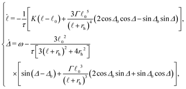 | (10) |
![[small script l]](https://www.rsc.org/images/entities/char_e146.gif) 02rh/(mhB) is a characteristic relaxation time scale. The dynamics of the magnetic cilium can now be studied using the above equations.
02rh/(mhB) is a characteristic relaxation time scale. The dynamics of the magnetic cilium can now be studied using the above equations.
We now discuss the different dynamical modes that the cilium can exhibit, and how the transition between them can be tuned using the frequency of the rotating magnetic field. In Fig. 2, the dynamical trajectories of the cilium are shown for three different values of ω (see also videos in the ESI,† Movies S1 and S2). We have chosen Δ0 = 0.0 (i.e. the direction of the magnetic moment of the hard magnet is along the main axis of the cilium).
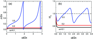 | ||
Fig. 2 Evolution of (a) the phase difference between the magnetic field and the cilium Δ and (b) the length of the spring ![[small script l]](https://www.rsc.org/images/entities/char_e146.gif) with time, under an external magnetic field with angular velocities ωτ = 0.1 (black), 0.2 (red), and 0.5 (blue). Other parameters are K = 1.0, Γ = 0.1, rh/ with time, under an external magnetic field with angular velocities ωτ = 0.1 (black), 0.2 (red), and 0.5 (blue). Other parameters are K = 1.0, Γ = 0.1, rh/![[small script l]](https://www.rsc.org/images/entities/char_e146.gif) 0 = 0.5, and Δ0 = 0.0, and initial conditions correspond to Δ = 0.0 and 0 = 0.5, and Δ0 = 0.0, and initial conditions correspond to Δ = 0.0 and ![[small script l]](https://www.rsc.org/images/entities/char_e146.gif) / /![[small script l]](https://www.rsc.org/images/entities/char_e146.gif) 0 = 1.0. Videos are shown in the ESI† as Movies_S1 and S2. 0 = 1.0. Videos are shown in the ESI† as Movies_S1 and S2. | ||
If the frequency of the rotating magnetic field is relatively low (see the black and red curves in Fig. 2), the phase difference Δ and the spring length ![[small script l]](https://www.rsc.org/images/entities/char_e146.gif) will go through an initial transient regime and then relax to equilibrium values, which can be obtained by solving
will go through an initial transient regime and then relax to equilibrium values, which can be obtained by solving  and
and  . In the stationary state, the cilium rotates with the magnetic field with a fixed phase difference Δ and a fixed length
 ![[small script l]](https://www.rsc.org/images/entities/char_e146.gif) . This is the phase-locked mode. In the two examples given in Fig. 2, where ωτ = 0.1 and 0.2, the cilium follows the magnetic field with a small phase lag. Moreover, in both cases, the magnetic dipole–dipole interaction between the soft and the hard magnet spheres is predominantly attractive, leading to a net contraction of the length of the spring.
. This is the phase-locked mode. In the two examples given in Fig. 2, where ωτ = 0.1 and 0.2, the cilium follows the magnetic field with a small phase lag. Moreover, in both cases, the magnetic dipole–dipole interaction between the soft and the hard magnet spheres is predominantly attractive, leading to a net contraction of the length of the spring.
The behaviour of the cilium changes if the frequency of the magnetic field is above a threshold value ωc, which depends on the parameters of the system as will be discussed later. As shown in Fig. 2, the cilium cannot relax to a stationary state anymore and will continue to undergo a cyclic motion that is out of synchrony with respect to the external magnetic field. In particular, there will be a continuous phase slip that will introduce alternating cycles of phase-lag and phase-lead between the cilium and the external magnetic field. The length of the spring ![[small script l]](https://www.rsc.org/images/entities/char_e146.gif) and Δ will also oscillate around a reference value. In this mode, the trajectory of the cilium exhibits a periodic ‘saw-like’ pattern.
and Δ will also oscillate around a reference value. In this mode, the trajectory of the cilium exhibits a periodic ‘saw-like’ pattern.
To help understand the transition, we can look at the large K limit, in which the deformation of the spring can be neglected because ![[small script l]](https://www.rsc.org/images/entities/char_e146.gif) /
/![[small script l]](https://www.rsc.org/images/entities/char_e146.gif) 0 = 1 + O(1/K). Freezing the elongation degree of freedom (by setting
0 = 1 + O(1/K). Freezing the elongation degree of freedom (by setting ![[small script l]](https://www.rsc.org/images/entities/char_e146.gif) =
= ![[small script l]](https://www.rsc.org/images/entities/char_e146.gif) 0) reduces the problem into a single-variable dynamical system, which takes the form
0) reduces the problem into a single-variable dynamical system, which takes the form
 | (11) |
 | (12) |
 is always strictly positive, albeit oscillating between a maximum and a minimum value, and therefore there will be a continuous phase slip between the cilium and the magnetic field. One can observe from eqn (12) that ωc increases linearly with Γ in the limit of large K, which suggests that phase locking is facilitated by the magnetic dipole–dipole interaction. The dependence on Γ is more complex for finite values of Δ0.
For finite values of K, the transition frequency ωc has similar generic dependence on Γ and Δ0. In Fig. 3, a 3D phase diagram in the space of (Γ, Δ0, ωτ) is shown. The phase diagram is obtained by solving eqn (10) numerically. The transition frequency ωc is found to be a periodic function of Δ0 with period π because of the symmetry in the magnetic dipole–dipole interaction (eqn (10)), and its oscillating amplitude increases with increasing Γ. The dependence of the transition frequency on these parameters provides helpful guidelines for the design and fabrication of magnetic cilia for specific applications. Such a mode transition was experimentally observed by Frka-Petesic et al. for a system of a paramagnetic rod driven by a rotating magnetic field,41 and also in other magnetic systems, such as nano- and micro-swimmers composed of a magnetic spherical head and a non-magnetic helical tail.42,43
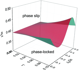 | ||
Fig. 3 Dynamic modes of the cilium as a function of (Γ, Δ0, ωτ). Other parameters are K = 1.0 and rh/![[small script l]](https://www.rsc.org/images/entities/char_e146.gif) 0 = 0.5. 0 = 0.5. | ||
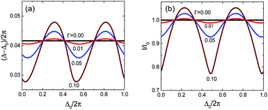
The behaviour of the soft-hard magnetic cilium in the stationary state can be explored in more detail by analyzing the fixed point structure of eqn (10); the results are shown in Fig. 4. We observe that for Γ = 0, the fixed point corresponds to ![[small script l]](https://www.rsc.org/images/entities/char_e146.gif) =
= ![[small script l]](https://www.rsc.org/images/entities/char_e146.gif) 0 and a fixed-point value for Δ that is independent of the value of Δ0 while depending on rh and ωτ; for rh/
0 and a fixed-point value for Δ that is independent of the value of Δ0 while depending on rh and ωτ; for rh/![[small script l]](https://www.rsc.org/images/entities/char_e146.gif) 0 = 0.5, and ωτ = 0.1 we obtain Δ ≈ Δ0 + 0.048 × 2π. In other words, in this case Δ − Δ0 and
0 = 0.5, and ωτ = 0.1 we obtain Δ ≈ Δ0 + 0.048 × 2π. In other words, in this case Δ − Δ0 and ![[small script l]](https://www.rsc.org/images/entities/char_e146.gif) in the stationary state are independent of Δ0. For non-vanishing Γ, we find that in the stationary state Δ − Δ0 and the length of the spring
in the stationary state are independent of Δ0. For non-vanishing Γ, we find that in the stationary state Δ − Δ0 and the length of the spring ![[small script l]](https://www.rsc.org/images/entities/char_e146.gif) depend on Δ0 as shown in Fig. 4(a) and (b). Control over the stationary state values for these quantities will provide the ability to optimize the performance of such an actuated magnetic cilium in practical applications. One such application, which we will discuss later, is the transport of fluid in channels.
depend on Δ0 as shown in Fig. 4(a) and (b). Control over the stationary state values for these quantities will provide the ability to optimize the performance of such an actuated magnetic cilium in practical applications. One such application, which we will discuss later, is the transport of fluid in channels.
3 3-dimensional motion
It has been shown that a magnetic cilium can move in either a locked-in mode or a saw-like mode if its motion is constrained in 2D space. This becomes different when the motion of the cilium is generalized to 3D [sketched in Fig. 5(a)]. For simplicity, we concentrate on the case where the magnetic moment lies in the same direction as the cilium, i.e., Δ0 = 0. Under a magnetic field B = B(sin![[thin space (1/6-em)]](https://www.rsc.org/images/entities/char_2009.gif) θbcos
θbcos![[thin space (1/6-em)]](https://www.rsc.org/images/entities/char_2009.gif) ϕb,sin
ϕb,sin![[thin space (1/6-em)]](https://www.rsc.org/images/entities/char_2009.gif) θbsin
θbsin![[thin space (1/6-em)]](https://www.rsc.org/images/entities/char_2009.gif) ϕb,cos
ϕb,cos![[thin space (1/6-em)]](https://www.rsc.org/images/entities/char_2009.gif) θb), the energy of the cilium with the hard magnet located at (l + rh) × (sin
θb), the energy of the cilium with the hard magnet located at (l + rh) × (sin![[thin space (1/6-em)]](https://www.rsc.org/images/entities/char_2009.gif) θccos
θccos![[thin space (1/6-em)]](https://www.rsc.org/images/entities/char_2009.gif) ϕc,sin
ϕc,sin![[thin space (1/6-em)]](https://www.rsc.org/images/entities/char_2009.gif) θcsin
θcsin![[thin space (1/6-em)]](https://www.rsc.org/images/entities/char_2009.gif) ϕc,cos
ϕc,cos![[thin space (1/6-em)]](https://www.rsc.org/images/entities/char_2009.gif) θc) can be expressed as,
θc) can be expressed as, | (13) |
Therefore, the forces acting on the hard magnet in the radial, zenith and azimuthal direction of the cilium are,
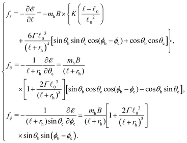 | (14) |
![[small script l]](https://www.rsc.org/images/entities/char_e146.gif) , and the orientational angles of the cilium, (θc,ϕc), can be obtained by solving
, and the orientational angles of the cilium, (θc,ϕc), can be obtained by solving | (15) |
Under a magnetic field with fixed θb and increasing azimuthal angle ϕb = ωt, two cases are discussed: (i) with the constraint that the polar angle of the cilium is kept equal to that of the magnetic field, i.e., θc = θb, and (ii) without the constraint on the polar angle of the cilium, i.e., θc can change flexibly with time.
As discussed above, for a magnetic cilium moving in 2D space, the cilium will rotate with the magnetic field with a finite phase lag, when the frequency of the rotating magnetic field is small. A similar phenomenon is also observed in the 3D case.
For the case (i) of θc = θb = π/3, if the frequency of the magnetic field is low, ωτ = 0.1, the azimuthal angle of the cilium ϕc increases linearly with time, t, i.e., the cilium moves in a locked-in mode [black dashed line in Fig. 5(b)]. If, however, the frequency of the magnetic field is high, ωτ = 0.5, ϕc increases and decreases alternately with time, i.e., it moves in a saw-like mode [black solid line in Fig. 5(b)].
However, the cilium moves differently in case (ii), where θc is not necessarily equal to θb. Under a magnetic field with either low frequency or high frequency, the cilium always moves in a locked-in mode [red lines in Fig. 5(b)]. The polar angle of the cilium in the stationary state θstac is almost the same as that of the magnetic field if the frequency of the magnetic field is low, for example if ωτ = 0.1, then θstac = 1.04 ≃ θb = π/3 (<1% difference between θstac and θb). If the frequency of the magnetic field is high, then θstac is smaller (larger) than the polar angle of the magnetic field for θb < π/2 (θb > π/2), for example in Fig. 5(b) if ωτ = 0.5, then θstac = 0.76 (28% difference between θstac and θb). Corresponding videos showing the motion of the cilium can be seen in the ESI† (Movies_S3–S6). As shown in Fig. 5(c), the cilium tends to move towards the north (south) pole of the sphere if the polar angle of the magnetic field is smaller (larger) than π/2 in case (ii). Note that there is a singularity point in Fig. 5(c), located at θb = π/2, where the cilium can move in a saw-like mode under a magnetic field with high frequency. However, the fixed point is not stable, and the cilium can move towards the north (south) pole if there is any perturbation in θc. So we can just treat the cilium as always moving in a locked-in mode in 3D space if θc is not constrained.
In ref. 24, Coq et al. studied the dynamics of chained superparamagnetic beads in 3-dimensional space. For θc not constrained (case (ii) in our work), they reported two dynamical regimes. When the polar angle of the rotating magnetic field was smaller than a critical value (magic angle), θb < 55°, and the frequency was low, then the polar angle of the cilium was almost the same as that of the magnetic field and the polar angle of the cilium decreased with increasing frequency of the magnetic field, matching our results. However, for θb > 55°, if the frequency of the magnetic field was high, they observed a saw-like motion of the cilium with both oscillating θc and ϕc, which differs from our cilium model. This is not surprising because of the different construction of the cilium considered in ref. 24.
4 Dynamics of the magnetic cilium in the vicinity of a wall
In any practical experimental setup, cilia will be placed near boundaries. For example, in biological systems, cilia are always attached to substrates, when performing their mechanical function either for swimming or fluid transport. The presence of a wall breaks the symmetry, and will allow the dynamical system to experience an additional periodic influence through hydrodynamic effects. Therefore, it will be important to examine the hydrodynamic effect of the boundary on the dynamics and performance of our model cilium.In this work, we adopt a no-slip boundary condition at the wall. Suppose that there is a wall in the z = 0 plane, and the soft magnet is pinned at a distance h0 from the wall. For simplicity, we assume that the motion of the cilium is constrained within the y–z plane. The height of the hard magnet, which can be described in terms of the dynamical variables as h(t) = h0 + ![[small script l]](https://www.rsc.org/images/entities/char_e146.gif) (t)sin
(t)sin![[thin space (1/6-em)]](https://www.rsc.org/images/entities/char_2009.gif) ϕc(t), controls the hydrodynamic interaction of the cilium with the wall. Within our formulation, the dynamical equations will be modified to (see the ESI†)
ϕc(t), controls the hydrodynamic interaction of the cilium with the wall. Within our formulation, the dynamical equations will be modified to (see the ESI†)
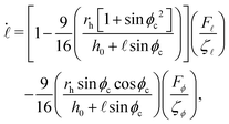 | (16) |
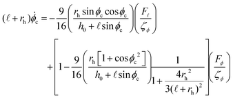 | (17) |
In Fig. 6, examples of how the cilium moves under a rotating magnetic field are provided, for various values of the height of the pinned soft magnet h0. As discussed in the previous section, both the spring length, ![[small script l]](https://www.rsc.org/images/entities/char_e146.gif) , and the phase difference between the cilium and the magnetic field, Δ, are constants in the stationary states for the case without the wall. However, the presence of the wall introduces oscillations in both
, and the phase difference between the cilium and the magnetic field, Δ, are constants in the stationary states for the case without the wall. However, the presence of the wall introduces oscillations in both ![[small script l]](https://www.rsc.org/images/entities/char_e146.gif) and Δ as shown in Fig. 6. We observe that the amplitudes of the oscillations increase if the cilium is pinned closer to the wall, as the symmetry breaking friction terms in eqn (16) and (17) become more pronounced.
and Δ as shown in Fig. 6. We observe that the amplitudes of the oscillations increase if the cilium is pinned closer to the wall, as the symmetry breaking friction terms in eqn (16) and (17) become more pronounced.
5 Fluid transport by the magnetic cilium
Cilia can be used in microfluidic applications, as the actuation mechanism can lead to a net transfer of force to the fluid, and hence, fluid transport. Here, we discuss the performance of our model cilium as a pump. A description of the problem that is consistent with the previous sections can be achieved by treating the hard magnet as a point force and evaluating the hydrodynamic flow field everywhere in the space bound by the surface using the Blake tensor.44Within this description, a point force F acting on the hard magnet at r = (x,y,z) will produce a velocity field at any other point r′ = (X,Y,Z) that depends linearly on the force as  , via the Blake tensor G(r′;r) that includes information about an image force at R = (x,y,−z). The explicit form of the Blake tensor is as follows44
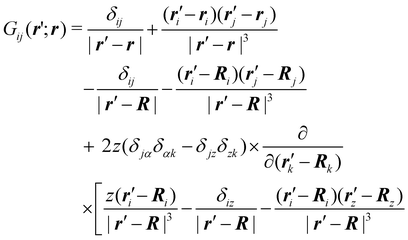 | (18) |
We use the volume flow rate27,45,46 in the y direction, which measures the flux through a half-plane perpendicular to the direction of pumping, to characterize the performance of a cilium as a pump at time t,
 | (19) |
![[small script l]](https://www.rsc.org/images/entities/char_e146.gif)
![[thin space (1/6-em)]](https://www.rsc.org/images/entities/char_2009.gif) cos
cos![[thin space (1/6-em)]](https://www.rsc.org/images/entities/char_2009.gif) ϕc − Fϕ
ϕc − Fϕ![[thin space (1/6-em)]](https://www.rsc.org/images/entities/char_2009.gif) sin
sin![[thin space (1/6-em)]](https://www.rsc.org/images/entities/char_2009.gif) ϕc and assuming the cilia are planted with surface density ρ, a dimensionless pump performance parameter S can be obtained by integrating the volume flow rate Q(t) over a period of the actuating magnetic field 2π/ω per area, i.e.,
ϕc and assuming the cilia are planted with surface density ρ, a dimensionless pump performance parameter S can be obtained by integrating the volume flow rate Q(t) over a period of the actuating magnetic field 2π/ω per area, i.e., | (20) |
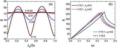
The pumping performance of such a magnetic cilium can be controlled by changing Δ0 and Γ; see Fig. 7(a). At low frequencies the best pump performance is obtained when Δ0 → π/2; in this case the length of the cilium is at its maximum due to the predominantly repulsive magnetic dipole–dipole interaction between the soft and the hard magnets (the two magnetic moments are perpendicular to the direction of the spring), and the tangential velocity of the hard magnet is also at its maximum. Conversely, the weakest pump performance is obtained when Δ0 → 0, because both the tangential velocity and the length of the cilium are at their minimum values (due to the attractive dipole–dipole interaction). When the frequency of the magnetic field ω is finite but smaller than the threshold ωc the cilium will follow the magnetic field with a finite phase difference, and the system will exhibit optimal pumping at a given value of Δ0.
When the system is phase-locked at low frequencies, the performance increases with the frequency up to the value of ωc, and then exhibits a dramatic drop just above this threshold, as shown in Fig. 7(b). This is a manifestation of the transition between phase locking and phase slip. The performance of the pump will thus be affected very strongly for frequencies near the threshold value if the value of ωc is modified due to changes in Γ and Δ0. Therefore, the magnetic interactions between the spheres and the elastic spring provide additional possibilities for controlling the pumping performance of our model cilium.
6 Conclusion
We propose a model magnetic artificial cilium, consisting of two magnetic spheres, one a soft magnet and one a hard magnet, connected by a spring. The simplicity of the model makes it amenable to a thorough analysis and the possibility of strong control as a function of the parameters of the system. When actuated by a rotating magnetic field, the cilium exhibits two distinct phases with a sharp tunable transition between them. The existence of a wall breaks the symmetry and induces additional oscillations in the length of the cilium and its orientation. The performance of the actuated cilium as a microfluidic pump is also investigated. The model can be generalized to include intrinsic anisotropy by using ellipsoidal colloids. Such a simple model of magnetically actuated cilia can serve as a promising starting point for engineering complex emergent properties in arrays of cilia, and help to understand their collective behaviour upon hydrodynamic coupling.26,27,47–50Conflicts of interest
There are no conflicts to declare.Acknowledgements
We would like to thank Andrej Vilfan, Masao Doi and Kenji Kikuchi for fruitful discussions, and Andrej Vilfan and Romain Müller for many helpful comments on the manuscript. This work has received funding from the Horizon 2020 research and innovation programme of the EU under grant agreement No. 665440. Open Access funding provided by the Max Planck Society.Notes and references
- C. Brennen and H. Winet, Annu. Rev. Fluid Mech., 1977, 9, 339–398 CrossRef.
- M. Silverman and M. I. Simon, Annu. Rev. Microbiol., 1977, 31, 397–419 CrossRef CAS.
- M. Salathe, Annu. Rev. Physiol., 2007, 69, 401–422 CrossRef CAS.
- P. Satir and S. T. Christensen, Annu. Rev. Physiol., 2007, 69, 377–400 CrossRef CAS.
- B. A. Evans, A. R. Shields, R. L. Carroll, S. Washburn, M. R. Falvo and R. Superfine, Nano Lett., 2007, 7, 1428–1434 CrossRef CAS.
- M. Vilfan, A. Potoc, N. Osterman, I. Poberaj and A. Vilfan, Proc. Natl. Acad. Sci. U. S. A., 2010, 107, 1844–1847 CrossRef CAS.
- P. O'Brien and R. Nuzzo, Artificial Cilia, The Royal Society of Chemistry, 2013, pp. P001–P265 Search PubMed.
- R. S. M. Rikken, R. J. M. Nolte, J. C. Maan, J. C. M. van Hest, D. A. Wilson and P. C. M. Christianen, Soft Matter, 2014, 10, 1295–1308 RSC.
- P. Tierno, Phys. Chem. Chem. Phys., 2014, 16, 23515–23528 RSC.
- R. M. Erb, J. J. Martin, R. Soheilian, C. Pan and J. R. Barber, Adv. Funct. Mater., 2016, 26, 3859–3880 CrossRef CAS.
- E. M. Gauger, M. T. Downton and H. Stark, Eur. Phys. J. E: Soft Matter Biol. Phys., 2009, 28, 231–242 CrossRef CAS.
- J. Belardi, N. Schorr, O. Prucker and J. Rühe, Adv. Funct. Mater., 2011, 21, 3314–3320 CrossRef CAS.
- N. Coq, A. Bricard, F.-D. Delapierre, L. Malaquin, O. du Roure, M. Fermigier and D. Bartolo, Phys. Rev. Lett., 2011, 107, 014501 CrossRef.
- S. N. Khaderi, C. B. Craus, J. Hussong, N. Schorr, J. Belardi, J. Westerweel, O. Prucker, J. Rühe, J. M. J. den Toonder and P. R. Onck, Lab Chip, 2011, 11, 2002 RSC.
- Y. Wang, Y. Gao, H. Wyss, P. Anderson and J. den Toonder, Lab Chip, 2013, 13, 3360 RSC.
- F. Fahrni, M. W. J. Prins and L. J. van IJzendoorn, Lab Chip, 2009, 9, 3413 RSC.
- R. Dreyfus, J. Baudry, M. L. Roper, M. Fermigier, H. A. Stone and J. Bibette, Nature, 2005, 437, 862–865 CrossRef CAS.
- A. Ghanbari, M. Bahrami and M. R. H. Nobari, Physical Review E, 2011, 83, 046301 CrossRef CAS.
- S. Kim, S. Lee, J. Lee, B. J. Nelson, L. Zhang and H. Choi, Sci. Rep., 2016, 6, 30713 CrossRef CAS.
- L. Zhang, J. J. Abbott, L. Dong, B. E. Kratochvil, D. Bell and B. J. Nelson, Appl. Phys. Lett., 2009, 94, 064107 CrossRef.
- W. H. Chong, L. K. Chin, R. L. S. Tan, H. Wang, A. Q. Liu and H. Chen, Angew. Chem., Int. Ed., 2013, 52, 8570–8573 CrossRef CAS.
- S. Yang, C. Cao, Y. Sun, P. Huang, F. Wei and W. Song, Angew. Chem., Int. Ed., 2015, 54, 2661–2664 CrossRef CAS.
- C. Goubault, P. Jop, M. Fermigier, J. Baudry, E. Bertrand and J. Bibette, Phys. Rev. Lett., 2003, 91, 260802 CrossRef CAS.
- N. Coq, S. Ngo, O. Du Roure, M. Fermigier and D. Bartolo, Phys. Rev. E: Stat., Nonlinear, Soft Matter Phys., 2010, 82, 041503 CrossRef.
- S. N. Khaderi, J. M. J. den Toonder and P. R. Onck, Biomicrofluidics, 2012, 6, 014106 CrossRef CAS.
- J. Han and C. S. Peskin, Proc. Natl. Acad. Sci. U. S. A., 2018, 115, 4417–4422 CrossRef CAS.
- N. Osterman and A. Vilfan, Proc. Natl. Acad. Sci. U. S. A., 2011, 108, 15727–15732 CrossRef CAS.
- H. Guo and E. Kanso, Phys. Rev. E, 2016, 93, 033119 CrossRef.
- C. Eloy and E. Lauga, Phys. Rev. Lett., 2012, 109, 038101 CrossRef.
- D. Tam and A. E. Hosoi, Pro. Natl. Acad. Sci. U. S. A., 2011, 108, 1001–1006 CrossRef CAS.
- D. R. Brumley, M. Polin, T. J. Pedley and R. E. Goldstein, Phys. Rev. Lett., 2012, 109, 268102 CrossRef.
- R. E. Goldstein, Annu. Rev. Fluid Mech., 2015, 47, 343–375 CrossRef.
- R. R. Bennett and R. Golestanian, J. R. Soc., Interface, 2015, 12, 20141164 CrossRef.
- F. Y. Ogrin, P. G. Petrov and C. P. Winlove, Phys. Rev. Lett., 2008, 100, 1–4 CrossRef.
- A. D. Gilbert, F. Y. Ogrin, P. G. Petrov and C. P. Winlove, Q. J. Mech. Appl. Math., 2011, 64, 239–263 CrossRef.
- G. Grosjean, M. Hubert, G. Lagubeau and N. Vandewalle, Phys. Rev. E, 2016, 94, 021101 CrossRef.
- B. Klaas, C. Agnese, B. Felix and F. Damien, Small, 2018, 14, 1704374 CrossRef.
- Y. Alapan, O. Yasa, O. Schauer, J. Giltinan, A. F. Tabak, V. Sourjik and M. Sitti, Science Robotics, 2018, 3, eaar4423 CrossRef.
- W. Hu, G. Z. Lum, M. Mastrangeli and M. Sitti, Nature, 2018, 554, 81–85 CrossRef CAS.
- A. Najafi and R. Golestanian, Phys. Rev. E: Stat., Nonlinear, Soft Matter Phys., 2004, 69, 062901 CrossRef.
- B. Frka-Petesic, K. Erglis, J. Berret, A. Cebers, V. Dupuis, J. Fresnais, O. Sandre and R. Perzynski, J. Magn. Magn. Mater., 2011, 323, 1309–1313 CrossRef CAS.
- D. Walker, M. Kübler, K. I. Morozov, P. Fischer and A. M. Leshansky, Nano Lett., 2015, 15, 4412–4416 CrossRef CAS.
- P. Katsamba and E. Lauga, Phys. Rev. Appl., 2016, 5, 1–14 Search PubMed.
- J. R. Blake, Math. Proc. Cambridge Philos. Soc., 1971, 70, 303 CrossRef.
- N. Liron, J. Fluid Mech., 1978, 86, 705 CrossRef.
- D. Smith, J. Blake and E. Gaffney, J. R. Soc., Interface, 2008, 5, 567–573 CrossRef CAS.
- N. Uchida and R. Golestanian, Phys. Rev. Lett., 2010, 104, 178103 CrossRef.
- R. Golestanian, J. M. Yeomans and N. Uchida, Soft Matter, 2011, 7, 3074 RSC.
- N. Bruot and P. Cicuta, Annu. Rev. Condens. Matter Phys., 2016, 7, 323–348 CrossRef.
- S. Chateau, J. Favier, U. D'Ortona and S. Poncet, J. Fluid Mech., 2017, 824, 931–961 CrossRef.
Footnote |
† Electronic supplementary information (ESI) available: In all videos, the green arrow denotes the direction of the magnetic field, and the direction of the magnetic moment of the hard magnet sphere is the same as the cilium direction, Δ0 = 0.0. Movie_S1: 2D dynamics of a magnetic cilium under an external magnetic field (green arrow) with angular velocity ωτ = 0.1. Other parameters are K = 1.0, Γ = 0.1, and rh/![[small script l]](https://www.rsc.org/images/entities/char_e146.gif) 0 = 0.5. Movie_S2: 2D dynamics of a magnetic cilium under an external magnetic field (green arrow) with angular velocity ωτ = 0.5. Other parameters are K = 1.0, Γ = 0.1, and rh/ 0 = 0.5. Movie_S2: 2D dynamics of a magnetic cilium under an external magnetic field (green arrow) with angular velocity ωτ = 0.5. Other parameters are K = 1.0, Γ = 0.1, and rh/![[small script l]](https://www.rsc.org/images/entities/char_e146.gif) 0 = 0.5. Movie_S3: 3D dynamics of a magnetic cilium under an external magnetic field (green arrow) with angular velocity ωτ = 0.1 with constraint θc = θb = π/3. Other parameters used are K = 1.0, Γ = 0.1, and rh/ 0 = 0.5. Movie_S3: 3D dynamics of a magnetic cilium under an external magnetic field (green arrow) with angular velocity ωτ = 0.1 with constraint θc = θb = π/3. Other parameters used are K = 1.0, Γ = 0.1, and rh/![[small script l]](https://www.rsc.org/images/entities/char_e146.gif) 0 = 0.5. Movie_S4: 3D dynamics of a magnetic cilium under an external magnetic field (green arrow) with angular velocity ωτ = 0.1 without constraint θc = θb = π/3. Other parameters used are K = 1.0, Γ = 0.1, and rh/ 0 = 0.5. Movie_S4: 3D dynamics of a magnetic cilium under an external magnetic field (green arrow) with angular velocity ωτ = 0.1 without constraint θc = θb = π/3. Other parameters used are K = 1.0, Γ = 0.1, and rh/![[small script l]](https://www.rsc.org/images/entities/char_e146.gif) 0 = 0.5. Movie_S5: 3D dynamics of a magnetic cilium under an external magnetic field (green arrow) with angular velocity ωτ = 0.5 with constraint θc = θb = π/3. Other parameters used are K = 1.0, Γ = 0.1, and rh/ 0 = 0.5. Movie_S5: 3D dynamics of a magnetic cilium under an external magnetic field (green arrow) with angular velocity ωτ = 0.5 with constraint θc = θb = π/3. Other parameters used are K = 1.0, Γ = 0.1, and rh/![[small script l]](https://www.rsc.org/images/entities/char_e146.gif) 0 = 0.5. Movie_S6: 3D dynamics of a magnetic cilium under an external magnetic field (green arrow) with angular velocity ωτ = 0.5 without constraint θc = θb = π/3. Other parameters used are K = 1.0, Γ = 0.1, and rh/ 0 = 0.5. Movie_S6: 3D dynamics of a magnetic cilium under an external magnetic field (green arrow) with angular velocity ωτ = 0.5 without constraint θc = θb = π/3. Other parameters used are K = 1.0, Γ = 0.1, and rh/![[small script l]](https://www.rsc.org/images/entities/char_e146.gif) 0 = 0.5. See DOI: 10.1039/c8sm02561d 0 = 0.5. See DOI: 10.1039/c8sm02561d |
| This journal is © The Royal Society of Chemistry 2019 |



![[r with combining tilde]](https://www.rsc.org/images/entities/i_char_0072_0303.gif)