 Open Access Article
Creative Commons Attribution 3.0 Unported Licence
A flowing pair of particles in inertial microfluidics†
Christian
Schaaf
 *,
Felix
Rühle
 and
Holger
Stark

Institut für Theoretische Physik, Technische Universität Berlin, Hardenbergstr. 36, 10623 Berlin, Germany. E-mail: Christian.Schaaf@tu-berlin.de
First published on 23rd January 2019
Abstract
A flowing pair of particles in inertial microfluidics gives important insights into understanding and controlling the collective dynamics of particles like cells or droplets in microfluidic devices. They are applied in medical cell analysis and engineering. We study the dynamics of a pair of solid particles flowing through a rectangular microchannel using lattice Boltzmann simulations. We determine the inertial lift force profiles as a function of the two particle positions, their axial distance, and the Reynolds number. Generally, the profiles strongly differ between particles leading and lagging in flow and the lift forces are enhanced due to the presence of a second particle. At small axial distances, they are determined by viscous forces, while inertial forces dominate at large separations. We identify cross-streamline pairs as stable fixed points in the lift force profiles and argue that same-streamline configurations are only one-sided stable. Depending on the initial conditions, the two-particle lift forces in combination with the Poiseuille flow give rise to three types of unbound particle trajectories, called moving-apart, passing, and swapping, and one type of bound trajectory, where the particles perform damped oscillations towards the cross-stream line configuration. The damping rate scales with Reynolds number squared, since inertial forces are responsible for driving the particles to their steady-state positions.
1 Introduction
The control of hydrodynamic flow fields on a microscopic scale is required in a variety of different applications in medicine, chemistry, and engineering.1 Microfluidic lab-on-a-chip devices allow users to sample2 and sort cells,3–5 engineer flow patterns,6 and they can be used for fabricating metamaterials.7,8 While a lot of research has been and is still being done in the field of low-Reynolds-number flows,9–11 especially industrial applications need a high throughput in the microchannels.12 The necessarily increased flow velocities initiated the field of inertial microfluidics. Here, fluid inertia is no longer negligible and new phenomena arise.13 One prominent example is the Segré-Silberberg effect,14,15 where rigid particles assemble in an annulus, halfway between channel center and wall, when pumped through a cylindrical channel. Its first observation in 1961 inspired many experimental works16,17 as well as analytical calculations18,19 and numerical simulations.20–24 It can be rationalized by a lift force profile, which a single particle experiences in the channel cross section17,25,26 and which can be used to implement an optimal-control scheme.27When the density of particles in the channel flow increases, they start to form microfluidic crystals or particle trains.28,29 Here, the particles assemble in a linear or zigzag pattern with a fixed axial distance typically ranging from 2.2 to 5 particle diameters.30,31 A deeper understanding of these particle trains is important for cell analysis32 and for understanding phonon excitations in microfluidic crystals.33,34 As particle densities are still small, pair interactions of the particles can provide a first understanding. At vanishing Reynolds numbers, pair interactions were studied by Batchelor and Green9 in an unbounded shear flow, who found open and closed trajectories for a pair of particles. Similar trajectories also occur in Poiseuille flow.11 They can all qualitatively be described by assuming that one particle follows the streamlines created by the flow distortion of the other particle.
Now, including inertia has a profound influence. In particular, the flow field around a single particle in a linear shear flow changes noticeably by losing the fore-aft symmetry compared to low Reynolds numbers.35,36 Applied to the trajectories of a particle pair, Kulkarni and Morris37 showed that closed trajectories in linear shear flow are replaced by reversing and spiraling trajectories. In microfluidic channels, flowing particle pairs, when staying together, perform damped oscillations at finite Reynolds numbers.29,38 Similar to the linear shear flow, Humphry et al.30 explained the oscillations and stability of the zigzag patterns by inward spiraling eddies. The eddies form due to the flow distortion of one particle, while the other one follows the streamline of such an eddy. This picture has recently been rationalized in ref. 39, where the oscillation is due to viscous flow distortion, while damping is a result of the acting inertial force that pushes the particle towards its equilibrium position. For same-streamline pairs, thorough experimental and numerical analysis has recently been performed.31 Usually, their particle distance is twice the distance of cross-streamline pairs. However, at higher particle Reynolds numbers, the particle pair is reported to relax at the same spacing as cross-streamline pairs.31,40 Some experiments also observed an increase of the axial spacing over time.29 Finally, it has recently been argued that the stability of such same-streamline pairs is a result of minimization of the kinetic energy of the fluid and analytical calculations have shown that the axial spacing of the particles is independent of the Reynolds number in the limit of small Re.39
In the following, we study the dynamics of a pair of two solid particles driven by Poiseuille flow through a rectangular microchannel. We perform lattice Boltzmann simulations of the Newtonian fluid and couple the particles to the fluid by the immersed boundary method. Up to now, the dynamics of rigid particles in inertial microchannel flow has mostly been analyzed by looking at their trajectories. Here, we focus on the inertial lift forces acting on the particles. The lift force profiles of both particles are crucially influenced by their neighbors and strongly depend on their distance along the channel axis. In particular, we identify cross-streamline pairs as stable fixed points in the lift force profiles and argue that same-streamline configurations are only one-sided stable. We find strong differences in the profiles for the particles leading and lagging in flow. Furthermore, lift forces in general are larger, which should enhance inertial focusing. Interestingly, how they scale with the Reynolds number depends on the axial particle distance. A linear scaling at close distances reveals interactions determined by viscous forces while the quadratic scaling for larger distances shows the dominating inertial forces. Finally, we categorize the different types of trajectories, on which a particle pair moves, in terms of their initial lateral positions. When the particles stay together, damped oscillatory trajectories occur towards the cross-streamline configuration, which can be explained using the two-particle lift force profiles. They have the advantage that they allow a fast and direct analysis of stable particle configurations without the need to simulate long trajectories.5
This article is organized as follows. In Section 2, we explain the set-up of our system, describe our implementation of the lattice-Boltzmann method, and how we couple the particles to the fluid. In Section 3, we present the results for the lift force profiles and the particle trajectories. We summarize and close with final remarks in Section 4.
2 Methods
We study a pair of solid spherical particles moving in a microfluidic channel flow at moderate Reynolds numbers. In the following, we shortly explain the microfluidic set-up and the lattice-Boltzmann method to simulate the hydrodynamic flow.2.1 Microfluidic set-up in the simulations
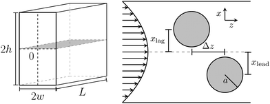
The channel of length L has a rectangular cross section (width 2w and height 2h) with an aspect ratio w/h = 0.5 (see Fig. 1). The aspect ratio w/h ≤ 0.5 is used to reduce the number of equilibrium positions to two sitting on the short axis,23 which is in contrast to a quadratic cross section where four equilibrium positions exist. The channel is filled with a Newtonian filled with density ρ and kinematic viscosity ν. To drive a Poiseuille flow in the rectangular channel, we apply a constant pressure force.41 The flow is characterized by the channel Reynolds number‡ Re = 2wumax/ν with the maximal flow velocity umax. It is directed along the z-direction, which we call axial direction, while movements perpendicular to the flow direction are referred to as lateral movements.In this Poiseuille flow, we place two spherical particles with the same radius a and neutral buoyancy. At moderate Reynolds numbers, fluid inertia becomes relevant and both particles experience lateral lift forces flift. They push the particles into the x, z plane containing the shorter cross-sectional axis23 and ultimately cause inertial focusing onto a specific position. In this work, we let the particles start already in the x,z plane to reduce the parameter space. To determine these lift forces in our simulations, we fix the particles' positions on the cross-sectional x axis and measure the forces that the fluid exerts on them. The lift forces are crucially influenced by the presence of the second particle and we will illustrate how they depend on the axial particle distance Δz in Section 3.1. The particles flow with different velocities along the channel axis depending on their positions in the channel cross section. So, when we measure the lift force profiles, we let the particles move with their center-of-mass velocity and keep Δz constant. This means that we effectively act with an axial force along the flow direction on each particle, resulting in small changes of the lift forces according to the Saffman effect.42 In Section 3.2, we analyze trajectories of the particle pair. Here, they can evolve freely without constraints.
Finally, along the flow direction, we use periodic boundary conditions. To ensure that the particles do not interact with their mirror images, we use a channel length of L = 30a + Δz.
2.2 Lattice-Boltzmann method
To solve the Navier–Stokes equations, we use the lattice Boltzmann method (LBM) in 3D based on 19 different velocity vectors (D3Q19)43 and rely on the Bhatnagar–Gross–Krook (BGK) collision operator.44 In the LBM, the fluid is modeled by a one-particle probability distribution fi(![[x with combining right harpoon above (vector)]](https://www.rsc.org/images/entities/i_char_0078_20d1.gif) ,t), which is determined on a cubic lattice with lattice spacing Δx. The distribution function depends on the lattice vectors
,t), which is determined on a cubic lattice with lattice spacing Δx. The distribution function depends on the lattice vectors ![[x with combining right harpoon above (vector)]](https://www.rsc.org/images/entities/i_char_0078_20d1.gif) and the index i stands for the 19 discretized velocity vectors
and the index i stands for the 19 discretized velocity vectors ![[c with combining right harpoon above (vector)]](https://www.rsc.org/images/entities/i_char_0063_20d1.gif) i pointing to the edges and the faces of a cube and the zero velocity. Now, fi(
i pointing to the edges and the faces of a cube and the zero velocity. Now, fi(![[x with combining right harpoon above (vector)]](https://www.rsc.org/images/entities/i_char_0078_20d1.gif) ,t) evolves during time Δt according to two alternating steps:
,t) evolves during time Δt according to two alternating steps: | (1) |
streaming: fi(![[x with combining right harpoon above (vector)]](https://www.rsc.org/images/entities/i_char_0078_20d1.gif) + + ![[c with combining right harpoon above (vector)]](https://www.rsc.org/images/entities/i_char_0063_20d1.gif) iΔt,t + Δt) = fi*( iΔt,t + Δt) = fi*(![[x with combining right harpoon above (vector)]](https://www.rsc.org/images/entities/i_char_0078_20d1.gif) ,t), ,t), | (2) |
Macroscopic quantities like the density ρ and the momentum density ρ![[u with combining right harpoon above (vector)]](https://www.rsc.org/images/entities/i_char_0075_20d1.gif) are defined via the zeroth and first moments of the distribution function:
are defined via the zeroth and first moments of the distribution function:
 | (3) |
 | (4) |
 | (5) |
The channel flow was driven by a constant body force according to the Guo-force scheme.47 In this scheme, the fluid momentum density evolves during each time step Δt according to
 | (6) |
Furthermore, we used regularized boundary conditions at the walls.48 The lattice-Boltzmann simulations were performed with the code provided by the Palabos project,49 which we supplemented by the implementation of particles using an immersed boundary method. Finally, we discretized the width of the channel along the x axis by 75 lattice cells.
We used the same simulation code as in our previous publication.23 We only added the event-based Euler method to prevent overlap between particles, which we describe at the end of the following section.
2.3 Modeling of solid particles
We modeled the particles by an immersed boundary and coupled them to the fluid by the method proposed by Inamuro.50 This immersed boundary method ensures the no-slip boundary condition at the particle surface by iteratively refining the body force gi acting on the surrounding fluid nodes. The particles are described by a triangulated sphere, which we obtain by subdividing the faces of an isocahedron and projecting the vertices on a sphere. To interpolate the fluid velocity at a vertex position between the nodes, we follow Peskin51 and use an interpolation kernel, which considers all neighboring nodes in a cube with edge length 4Δx around the vertex position. For further details on these methods, we refer the reader to the original publications and our previous work.23Furthermore, the approach assumes that the particles are filled with a Newtonian fluid, which is unphysical. In order to compensate for this, we also apply Feng's rigid body approximation52 and add an additional force acting on the particle so that it moves like a solid particle. With all contributions, the equations of motion for the particles are given by
![[r with combining right harpoon above (vector)]](https://www.rsc.org/images/entities/i_char_0072_20d1.gif) i(t + Δt) = i(t + Δt) = ![[r with combining right harpoon above (vector)]](https://www.rsc.org/images/entities/i_char_0072_20d1.gif) i(t) + i(t) + ![[v with combining right harpoon above (vector)]](https://www.rsc.org/images/entities/i_char_0076_20d1.gif) i(t) i(t) | (7) |
 | (8) |
 | (9) |
![[r with combining right harpoon above (vector)]](https://www.rsc.org/images/entities/i_char_0072_20d1.gif) ,
, ![[v with combining right harpoon above (vector)]](https://www.rsc.org/images/entities/i_char_0076_20d1.gif) , and
, and ![[small omega, Greek, vector]](https://www.rsc.org/images/entities/i_char_e13e.gif) are, respectively, the position, velocity, and angular velocity. Finally, M and I stand for the mass and moment of inertia.
are, respectively, the position, velocity, and angular velocity. Finally, M and I stand for the mass and moment of inertia.
For some trajectories, which we show in Section 3.2, the two particles touch each other. To avoid overlap, we use an event-based Euler step for the particles. When the particles are so close that they would overlap in the next time step, we reduce the time step to Δ![[t with combining tilde]](https://www.rsc.org/images/entities/i_char_0074_0303.gif) so that the particles just touch, perform the collision between the particles, and finish the remaining time step with length Δt − Δ
so that the particles just touch, perform the collision between the particles, and finish the remaining time step with length Δt − Δ![[t with combining tilde]](https://www.rsc.org/images/entities/i_char_0074_0303.gif) with the new values for the particle velocities and angular velocities. To realize the collision, we follow ref. 53 and consider two rough hard spheres53 so that during collision, angular momentum is also exchanged.
with the new values for the particle velocities and angular velocities. To realize the collision, we follow ref. 53 and consider two rough hard spheres53 so that during collision, angular momentum is also exchanged.
3 Results
3.1 Lift force profiles
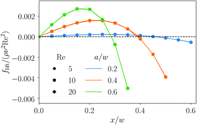
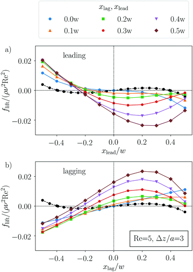
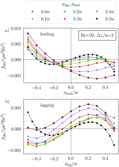
The dynamics of a particle pair in inertial microfluidics is best captured by the particle–particle lift force profiles. They quantify the lift forces that the particles experience in the presence of the other particle either leading or lagging in flow [see Fig. 1 for the geometry]. Zero forces correspond to fixed points or equilibrium positions in the channel cross section and the magnitude of the force indicates how fast the particles become focused on their equilibrium positions. When both particles are mirrored at the channel axis, the lift force reverses sign. More importantly, when the flow direction is reversed such that the leading particle becomes lagging and vice versa, the lift force profiles change, since due to secondary flow in the inertial regime, the leading and lagging particles experience different flow fields.In previous work, we already analyzed the lift force profile for a single rigid particle.20,23 This force profile changes sign when mirrored at the channel center and scales with the Reynolds number, ∝ Re2 (Fig. 2). Typically, one finds an unstable fixed point in the channel center and stable off-centered fixed points or equilibrium positions (indicated by a negative slope) along symmetry axes in the channel cross section. In this work, we will focus on the two-particle lift force profiles as a function of the axial particle distance Δz (measured along the flow direction), the lateral coordinates xlead, xlag and the channel Reynolds number Re as indicated in Fig. 1. In what follows, we concentrate on particles with radius a/w = 0.4.
For the leading particle [see Fig. 3(a)], we find only stable fixed points in the channel side opposite to the location of the lagging particle, the other fixed points have disappeared. However, the new equilibrium positions are closer to the channel center compared to the single-particle case (black line) and, ultimately, for xlag = 0, the stable fixed point is in the channel center. In contrast, when the leading particle resides in the upper half of the channel, the fixed point of the lagging particle in the other channel side [Fig. 3(b)] becomes unstable and stable equilibrium points only exist very close to the upper channel wall for sufficiently large xlead. Interestingly, the configuration with xlead = xlag = 0 is not stable. Finally, note that the lift force profiles of the leading and lagging particles differ from each other due to secondary flow as stated in the beginning.
When we increase the distance Δz of the two particles along the flow direction, the lift force profiles are more similar in shape to the profile of a single particle, however shifted downwards (leading particle) or upwards (lagging particle) (Fig. 4). In particular, for the cases where the other particle is relatively close to the channel center (x/w < 0.3), two stable equilibrium positions in the two respective sides of the channel are still present. In addition, when the neighboring particle is in the channel center (x/w = 0), the force profile agrees with the single-particle case close to the channel center (blue lines in Fig. 4) but the stable equilibrium positions are located closer to the channel walls. Finally, by increasing the axial distance between the particle pair, the strength of the lift forces decreases compared to Fig. 3.
The existence of stable fixed points in the lateral force profiles of both particles does not necessarily define a stable particle configuration, since particles closer to the channel center move faster than particles near the channel walls. For a stable pair configuration, the fixed points of both particles have to be at the same distance from the channel center.§ From Fig. 4, we observe that this might be possible for xlag/w = −xlead/w around 0.4, which we will indeed confirm in the next paragraph and further below in Section 3.2. In contrast, when the particles are close together, for example at Δz/a = 3 as in Fig. 3, such a stable pair configuration is not possible.
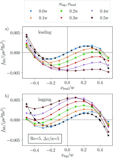 | ||
| Fig. 4 Lateral lift force profiles along the short axis for the leading (a) and lagging (b) particles for Re = 5, particle radius a/w = 0.4, and at the larger axial distance Δz/a = 5 compared to Fig. 3. The curve parameters are the positions of the lagging (a) or leading (b) particle, respectively. The black dotted lines correspond to the single-particle force profile. | ||
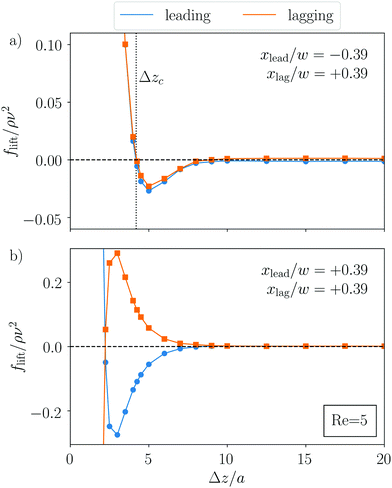
In Fig. 5, we fix the lateral positions of both particles at the single-particle equilibrium distance |xlead/lag|/w = 0.39, assuming that in stable two-particle configurations, this position is approximately the same, and vary their axial distance. For stable configurations, the lift forces acting on both particles have to vanish at the same Δz. We analyze both pair configurations observed in experiments: same-streamline pairs, where both particles occupy the same side of the channel, and cross-streamline configuration, where they occupy opposite sides. For the cross-streamline configuration [see Fig. 5(a)], the lift forces indeed vanish at the same Δzc. This fixed point is also stable since along the channel axis, it implies an effective repulsion for Δz < Δzc and an effective attraction for Δz > Δzc, as the following argumentation shows. When the particles move closer together, the lift forces acting on both particles are positive. They push the leading particle with negative xlead to the center, which thus moves faster, and the lagging particle with positive xlead towards the walls, which thus slows down. As a result, the particle distance increases again. The same argumentation holds when the the particles are moved apart. This demonstrates that the cross-streamline configurations are stable against small perturbations. The axial distance of Δz/a ≈ 4.1 corresponds well with experimental values.29,30
However, we do not find stable configurations for the same-streamline case [see Fig. 5(b)]. Here, both particles are on the same side of the channels and their lift forces have opposite signs. A fixed point at a close distance Δz/a = 0.225 exists, but the same argumentation as before reveals that it is unstable against perturbations. This appears to be a contradiction to what is found in several experiments, where same-streamline particle trains and pairs where observed.28,30,31 However, we note that the lift forces in Fig. 5(b) vanish at a distance of about 10a, where particles move independently from each other. Interestingly, this particle distance is also observed in ref. 30 and 31 for the trains and pairs at smaller Reynolds numbers. Indeed, we expect to see same-streamline trains and pairs with such a distance form in our simulations starting from smaller separations. However, they are only one-sided stable. When the trains and pairs are squeezed together, the particles relax again to a spacing of 10a but when they are pushed apart, they cannot contract again. Indeed, such an increase of the axial distance was observed by Lee et al.,29 when the particle train passed through an expansion-contraction channel geometry.
We were not able to reproduce the observations that the same-streamline axial distance decreases to about half the spacing at larger particle Reynolds numbers.31,40 We carefully checked different channel aspect ratios and mesh resolutions but found only an axial spacing of 8–10a. A possible source of error might be the immersed-boundary method, which we use to implement the flowing particle. However, the results in ref. 54, for example, show that this method captures the principal behavior of solid particles in laminar flow. Furthermore, the otherwise good agreement with the experimental findings makes us confident that the results presented here capture the dominant effects.
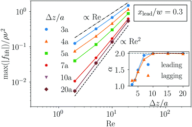
We now take a closer look at how the lift force scales with the Reynolds number Re. We already realized that for small particle distances, the two-particle lift forces no longer scale with Re2 as in the single-particle case. However, it is also clear that for large distances, this scaling has to be recovered since the influence of the two particles on each other strongly decreases. To analyze this aspect in more detail, we fixed the leading particle at xlead/w = 0.3 and vary xlag. We determined the maximum value of the magnitude of the lift force profile for the lagging particle and plotted it versus Reynolds number for several particle distances.¶Fig. 7 shows the results in double-logarithmic scale. One clearly recognizes a power-law scaling with exponent α: fmaxlift ∝ Reα. In the inset, we plot α versus Δz for both the leading and lagging particles. Indeed, we find α = 2 for Δz/a > 7. When the particles approach each other, the scaling exponent decreases to almost α = 1 for Δz = 3a. This scaling helps to further understand the character of the lift force, in particular, when two particles interact. A particle disturbs the fluid flow, which then influences the motion of nearby particles through a viscous coupling. This is the dominant contribution to the lift force at small distances, as indicated by the linear scaling of the lift force with Re. The inertial contribution takes over at large distances, where the disturbance flow from the neighboring particle is weak, and one recovers the typical scaling for the inertial lift force, flift ∝ Re2. So, our analysis confirms the picture of ref. 29, which explicitly speaks about a viscous disturbance flow.
So, both Fig. 5 and 7 indicate that beyond the distance Δz/a ≈ 7, the particles essentially do not interact. In ref. 55, it is argued that hydrodynamic interactions in a microchannel are screened for distances larger than the width of the channel cross section. In our case, taking a particle radius of a = 0.4w, a distance of 7a corresponds to 2.8w, which is close to the channel width of 2w. This explains our observation.
3.2 Two-particle trajectories
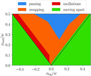
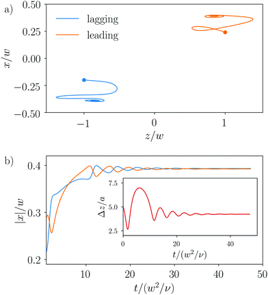
We now present the possible trajectories, on which two particles traverse as a result of the coupled lift force profiles presented in Section 3.1 and advection in the Poiseuille flow. The different types occur depending on the starting lateral positions and the axial distance. Thus, in Fig. 9, we categorize them in a diagram for the starting lateral positions xlag and xlead, while keeping the starting axial distance fixed. We identified four different kinds of coupled particle movements, which we term moving apart, passing, swapping, and damped oscillations.We name the first three types of trajectories unbound as their particles drift apart and reach their equilibrium lateral positions at large axial distances, where they do not influence each other anymore. We will analyze these trajectories in more detail further below. We also observe bound trajectories, where the two particles ultimately perform damped oscillations about their equilibrium lateral positions. They occur in the narrow red region in Fig. 9, where the particles occupy opposing channel sides with the lagging particle only a little faster than the leading such that they can stay together. We start by describing the bound trajectories.
Ultimately, the particles reach their final lateral equilibrium positions, which agree with the positions of single particles, and their distance is given by the stable fixed point identified in Fig. 5(a).
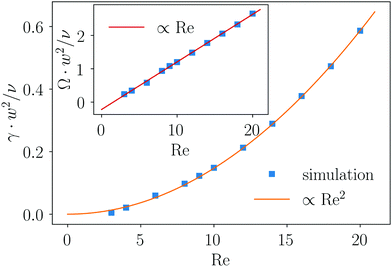
In the following, we analyze how oscillation frequency Ω and damping rate γ behave as a function of the Reynolds number (see Fig. 11). We determined Ω by measuring the time between maximal displacements and γ by an exponential fit for the amplitudes decaying in time. For the oscillation frequency Ω (inset of Fig. 11), we find a linear scaling with the Reynolds number, which indicates that the oscillations are due to the viscous coupling between the particles. In contrast, the damping rate scales quadratically with the Reynolds number since inertial lift forces drive them to their equilibrium positions. According to Fig. 7, these inertial forces act here as a pertubation. Note that our findings on the damped oscillations are in full agreement with ref. 39.
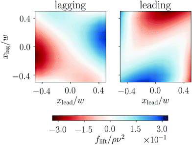
The dynamics of the oscillating particle pair, which we discussed in Fig. 10, can be nicely illustrated using lift-force contour plots similar to the one we determined in Section 3.1 (see Fig. 8 and video in ESI†) but now for Re = 10. We start with the initial conditions
| xlag/w = −0.2, xlead/w = 0.24, and Δz/a = 5. |
We can now follow the particles in the lift-force contour plots as indicated in the video to understand their trajectories in the x, z plane. In the beginning, the lagging particle is faster as it is closer to the center. The signs of both lift forces are such that they push the particles towards the walls. In this phase, since the lagging particle is faster, the axial distance decreases. The leading particle turns around and moves away from the upper wall, while the lagging particle still moves towards the lower wall. Thus, both forces are negative. Ultimately, the lagging particle is closer to the wall than the leading particle. It moves slower and the axial distance increases. By following the trajectories further, the signs of the lift forces always indicate the lateral direction of the moving particles. In the end, they show damped oscillations about the zero lines of the contour plots in agreement with the spiraling motion in the x,z plane. Finally, after a few oscillations, the particles reach their stable equilibrium positions, where the lift forces are zero.
Interestingly, we find that all bound particle pairs performing damped oscillations assemble at an axial distance of Δz/a ≈ 4.1 independent of their initial conditions or the Reynolds number, which we varied between 2 and 20 (see Fig. 13). The independence from Re was already mentioned in ref. 39. As already discussed in Section 3.1.1, this value for the axial distance is in good agreement with experimental and theoretical results.28,30,31,39 The scaling of the lift force with Re (cf.Fig. 7) indicates that at this equilibrium distance, the particle interactions are dominated by a viscous disturbance flow as already mentioned above and in ref. 29 and 39. The shape of this flow does not depend on the Reynolds number, which explains why the equilibrium distance is independent of Re.
In this article, we explain the formation of stable particle pairs by a stable fixed point, where the lift forces acting on the particles become zero and where both particles have the same distance from the channel center so that they drift with the same velocity. The formation of these cross-streamline pairs was already explained in ref. 30. The authors argue that a particle creates a viscous disturbance flow, which contains eddies or vortices on the opposite side of the channel. We also see these eddies in our simulated flow field, as indicated by the streamlines in the co-moving frame in Fig. 12. The second particle then occupies the center of an eddy, where it does not move relative to the first particle. Since the viscous disturbance flow is independent of Re, the position of the eddy does not change with Re, in agreement with our argument in the previous paragraph. We fully agree with this explanation. The advantage of the lift force profiles introduced in this article is that they unambigously show whether equilibrium positions are stable fixed points but that they also determine the full dynamics of a particle pair. We demonstrated this before when describing the oscillatory motion of the bound particle pair.
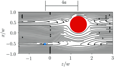 | ||
| Fig. 12 Streamlines in the co-moving frame of a single particle (red) at Re = 10 show the formation of an eddy (blue) on the opposite side of the channel. | ||
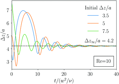 | ||
| Fig. 13 Oscillation of axial distance returns to the same axial distance independent of the initial axial distance. | ||
In addition to the cross-streamline pairs, Hood and Roper39 also formulated a theory that predicts stable same-streamline pairs. However, in our analysis, particles moving on the same side of the channel never form stable bound states. This does not imply that we will not see particle trains, where all particles assemble at the same side of the channel. According to the results presented here and from preliminary simulations, particles in a train will drift apart until the lift forces become zero at Δz/a ≈ 10 but they will not contract to this separation when initialized at a larger axial spacing. This is in contrast to a zigzag ordered crystal, which contracts to its equilibrium spacing.
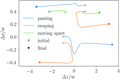 | ||
| Fig. 14 Three exemplary trajectories for unbound passing, swapping and moving-apart states drawn in the center-of-mass frame. Further parameters are a/w = 0.4 and Re = 10. Flow goes along the z axis. | ||
Passing trajectories occur since the lagging particle is closer to the channel center and therefore faster than the leading particle. So, they change order in the axial direction (blue line in Fig. 14). During this overtaking, the displacement of the two particles is asymmetric. The particle closer to the channel center is displaced much more strongly and the offset is clearly visible after the passing event. Then, the axial distance increases and the particles assume their single-particle positions due to inertial focusing. We note that the particles do touch during the overtaking as we did not implement any lubrication approximation. However, due to our event-based Euler step, they do not overlap.
When moving on swapping trajectories (orange line in Fig. 14), the faster lagging particle does not succeed in overtaking the leading particle. Instead, the particles come close to each other and then swap lateral position, which makes the leading particle the faster particle, so that they keep their axial order. When the particles move apart, they have interchanged their distances to the channel center. For example, for the orange trajectories in Fig. 14, one finds xafterlead ≈ −xbeforelag and vice versa. Note that similar trajectories in linear shear flow were called a reversing trajectory.37
In general, we see very similar types of trajectories also at low Reynolds numbers,11 indicating that they are governed by the viscous particle coupling and the Poiseuille flow profile. Inertial forces are responsible for focusing the particles on positions determined either by the two-particle or single-particle lift force profiles. Although the two-particle trajectories studied in this article are often unbound, in preliminary results, we find that they are the fundamental building blocks in the formation of multi-particle lattices. Our goal is to explain the formation of particle lattices also using these trajectories in a future work.
4 Conclusion
Understanding the pair interactions of two particles in inertial microfluidics is an important step for understanding collective dynamics such as the formation of particle trains.In this work, we studied the lift force profiles and the trajectories of a pair of two solid particles driven by Poiseuille flow through a rectangular microchannel. The lift force profiles of both particles are strongly influenced by their neighbors and depend on the particle distance along the channel axis. They clearly differ between the leading and lagging particles and the lift forces are stronger compared to a single particle. The increased lift force should enhance particle focusing by driving them faster towards their equilibrium positions. At close distance, the lift- force profiles differ strongly from the profile of a single particle and do not allow for stable pair configurations. However, when increasing the axial distance or the channel Reynolds number, the profiles appear similar in shape but are shifted by constant forces. Interestingly, at small axial distances below Δz/a = 4, the strength of the lift forces scales with Re, indicating that hydrodynamic interactions between the particles are dominated by viscous forces, while for distances of Δz/a = 10 and larger, scaling is quadratic in Re, showing the importance of inertial forces. In between, the scaling follows Reα with the exponent varying smoothly from 1 to 2 with increasing Δz.
We further analyzed the axial dependence of the lift force profile on the particle distance for two configurations found in experiments, same-streamline and cross-streamline pairs. Cross-streamline pairs correspond to a stable fixed point with an axial distance of Δz/a ≈ 4.1. However, our results indicate that there is no stable fixed point for same-streamline pairs. Here, particles just drift apart until their interaction vanishes at around the axial distance found in experiments. This indicates that these particle pairs or the corresponding trains are only one-sided stable. When they are squeezed together, the particles relax to the spacing of vanishing interactions, while when they are pushed apart, they cannot contract again. This is explicitly seen in experiments.29 Our results do not agree with the recent work of ref. 39, which argues that stable same-streamline pairs follow from minimizing the kinetic energy of the fluid. For larger Reynolds numbers, we cannot reproduce the particle pairs occurring with an axial distance half the value found at smaller Re as reported in ref. 31.
We also presented the lift force profiles of leading and lagging particles in a two-dimensional representation as a function of both lateral particle positions. These two-dimensional plots determine the coupled dynamics and the trajectories of two floating particles. We identified four types of particle trajectories depending on the initial lateral positions of the leading and lagging particles. Three of them are unbound, where the particle distance ultimately increases until both particles reach their single-particle equilibrium positions. In the moving-apart trajectories, the leading particle is mostly faster than the lagging particle and the pair drifts apart. If the lagging particle is much faster, it overtakes and thereby changes axial order with the leading particle in what we call passing trajectories. If the lagging particle is not much faster, it only approaches the leading particle but then they exchange their lateral positions and move apart again. Thus, they move on swapping trajectories. Finally, bound trajectories occur for xlag ≈ −xlead, where the axial distance and lateral positions of the particles perform damped oscillations while reaching their equilibrium values. As such a damping does not occur in Stokes flow, it is clearly an inertial effect. Consequently, the damping rate scales with the Reynolds number squared, while the oscillation frequency increases linearly with Re, in agreement with a recent study.39 Interestingly, for the specific particle radius studied here, all oscillating trajectories ultimately end at an axial distance of Δz/a ≈ 4.1, independent of the initial conditions and the Reynolds number. We argue that this stable configuration is determined by a stable fixed point, where the lift forces on both particles vanish and where they move with the same speed. This explanation adds further to the understanding of why cross-stream line pairs form. It concentrates on the acting forces instead of looking directly at the streamline pattern of a single particle as in ref. 30.
In this work, we concentrated on a specific channel cross section such that the particles only move in the x,z-plane and we fixed the ratio of particle radius to channel width. We add some final remarks on if and how we expect our findings to change with the setting. Our results indicate that the specific type of the bound and unbound trajectories depends on the initial location within the x,z plane and thus on the initial relative velocity. So, we expect a similar phase diagram even when particles do not start in the x,z plane. The same type of trajectories should exist in channels with a square cross section, where four equilibrium positions exist. However, the question is whether swapping trajectories are realized, when particles do not move in a plane. Finally, if confinement becomes stronger with increasing particle radius, we expect larger lift forces as the scaling flift ∝ ρν2Re2(a/w)4 for single particles suggests.18 Furthermore, Hood and Roper39 found that the axial distance of the bound two-particle state increases with increasing particle size.
With our investigations, we hope to shed further light on the collective dynamics and ordering of particles flowing through microfluidic channels at moderate Reynolds numbers. This should be useful in designing microfluidic crystal structures as well as developing and improving particle separation and sorting techniques in inertial microfluidics.
Conflicts of interest
There are no conflicts of interest to declare.Acknowledgements
We thank C. Prohm for providing the source code and for initial work on the project. We acknowledge support from the Deutsche Forschungsgemeinschaft in the framework of the Collaborative Research Center SFB 910.Notes and references
- J. M. Martel and M. Toner, Annu. Rev. Biomed. Eng., 2014, 16, 371 CrossRef CAS PubMed.
- O. Otto, P. Rosendahl, A. Mietke, S. Golfier, C. Herold, D. Klaue, S. Girardo, S. Pagliara, A. Ekpenyong, A. Jacobi, M. Wobus, N. Töpfner, U. F. Keyser, J. Mansfeld, E. Fischer-Friedrich and J. Guck, Nat. Methods, 2015, 12, 199 CrossRef CAS PubMed.
- S. C. Hur, N. K. Henderson-MacLennan, E. R. B. McCabe and D. Di Carlo, Lab Chip, 2011, 11, 912 RSC.
- H. W. Hou, A. A. S. Bhagat, A. G. Lin Chong, P. Mao, K. S. Wei Tan, J. Han and C. T. Lim, Lab Chip, 2010, 10, 2605 RSC.
- C. Schaaf and H. Stark, Soft Matter, 2017, 13, 3544 RSC.
- H. Amini, E. Sollier, M. Masaeli, Y. Xie, B. Ganapathynian, H. A. Stone and D. Di Carlo, Nat. Commun., 2013, 4, 1826 CrossRef PubMed.
- M. Golosovsky, Y. Saado and D. Davidov, Appl. Phys. Lett., 1999, 75, 4168 CrossRef CAS.
- V. G. Kravets, O. P. Marshall, R. R. Nair, B. Thackray, A. Zhukov, J. Leng and A. N. Grigorenko, Opt. Express, 2015, 23, 1265 CrossRef CAS PubMed.
- G. K. Batchelor and J. T. Green, J. Fluid Mech., 1972, 56, 375 CrossRef.
- C. L. Darabaner and S. G. Mason, Rheol. Acta, 1967, 6, 273 CrossRef CAS.
- S. Reddig and H. Stark, J. Chem. Phys., 2013, 138, 234902 CrossRef CAS PubMed.
- J. Zhang, S. Yan, D. Yuan, G. Alici, N.-T. Nguyen, M. E. Warkiani and W. Li, Lab Chip, 2015, 16, 10 RSC.
- D. Di Carlo, Lab Chip, 2009, 9, 3038 RSC.
- G. Segré and A. Silberberg, Nature, 1961, 189, 209 CrossRef.
- G. Segré and A. Silberberg, J. Fluid Mech., 1962, 14, 115 CrossRef.
- A. A. S. Bhagat, S. S. Kuntaegowdanahalli and I. Papautsky, Phys. Fluids, 2008, 20, 101702 CrossRef.
- D. Di Carlo, J. F. Edd, K. J. Humphry, H. A. Stone and M. Toner, Phys. Rev. Lett., 2009, 102, 094503 CrossRef PubMed.
- E. S. Asmolov, J. Fluid Mech., 1999, 381, 63 CrossRef CAS.
- K. Hood, S. Lee and M. Roper, J. Fluid Mech., 2015, 765, 452 CrossRef CAS.
- C. Prohm, M. Gierlak and H. Stark, Eur. Phys. J. E: Soft Matter Biol. Phys., 2012, 35, 80 CrossRef CAS PubMed.
- B. Chun and A. J. C. Ladd, Phys. Fluids, 2006, 18, 031704 CrossRef.
- T. Krüger, B. Kaoui and J. Harting, J. Fluid Mech., 2014, 751, 725 CrossRef.
- C. Prohm and H. Stark, Lab Chip, 2014, 14, 2115 RSC.
- Y. Yan, J. F. Morris and J. Koplik, Phys. Fluids, 2007, 19, 113305 CrossRef.
- J.-P. Matas, J. F. Morris and É. Guazzelli, J. Fluid Mech., 2009, 621, 59 CrossRef.
- C. Prohm, N. Zöller and H. Stark, Eur. Phys. J. E: Soft Matter Biol. Phys., 2014, 37, 36 CrossRef PubMed.
- C. Prohm, F. Tröltzsch and H. Stark, Eur. Phys. J. E: Soft Matter Biol. Phys., 2013, 36, 118 CrossRef PubMed.
- J.-P. Matas, V. Glezer, É. Guazzelli and J. F. Morris, Phys. Fluids, 2004, 16, 4192 CrossRef CAS.
- W. Lee, H. Amini, H. A. Stone and D. Di Carlo, Proc. Natl. Acad. Sci. U. S. A., 2010, 107, 22413 CrossRef CAS PubMed.
- K. J. Humphry, P. M. Kulkarni, D. A. Weitz, J. F. Morris and H. A. Stone, Phys. Fluids, 2010, 22, 081703 CrossRef.
- S. Kahkeshani, H. Haddadi and D. Di Carlo, J. Fluid Mech., 2016, 786, R3 CrossRef.
- J. F. Edd, D. Di Carlo, K. J. Humphry, S. Köster, D. Irimia, D. A. Weitz and M. Toner, Lab Chip, 2008, 8, 1262 RSC.
- T. Beatus, T. Tlusty and R. Bar-Ziv, Nat. Phys., 2006, 2, 743 Search PubMed.
- U. D. Schiller, J.-B. Fleury, R. Seemann and G. Gompper, Soft Matter, 2015, 11, 5850 RSC.
- G. Subramanian and D. L. Koch, Phys. Rev. Lett., 2006, 96, 134503 CrossRef CAS PubMed.
- G. Subramanian and D. L. Koch, Phys. Fluids, 2006, 18, 073302 CrossRef.
- P. M. Kulkarni and J. F. Morris, J. Fluid Mech., 2008, 596, 413 Search PubMed.
- H. Amini, W. Lee and D. Di Carlo, Lab Chip, 2014, 14, 2739 RSC.
- K. Hood and M. Roper, Phys. Rev. Fluids, 2018, 3, 094201 CrossRef.
- Y. Gao, P. Magaud, L. Baldas, C. Lafforgue, M. Abbas and S. Colin, Microfluid. Nanofluid., 2017, 21, 154 CrossRef.
- H. Bruus, Theoretical Microfluidics, Oxford University Press, Oxford, New York, 2008 Search PubMed.
- P. G. T. Saffman, J. Fluid Mech., 1965, 22, 385 CrossRef.
- S. Succi, The Lattice Boltzmann Equation for Fluid Dynamics and Beyond, Clarendon Press, Oxford University Press, Oxford, New York, 2001 Search PubMed.
- P. L. Bhatnagar, E. P. Gross and M. Krook, Phys. Rev., 1954, 94, 511 CrossRef CAS.
- B. Dünweg and A. J. Ladd, Advances in Polymer Science, Springer Berlin Heidelberg, 2008 Search PubMed.
- T. Krüger, F. Varnik and D. Raabe, Comput. Math. Appl., 2011, 61, 3485 CrossRef.
- Z. Guo, C. Zheng and B. Shi, Phys. Rev. E: Stat. Phys., Plasmas, Fluids, Relat. Interdiscip. Top., 2002, 65, 046308 CrossRef PubMed.
- J. Latt, B. Chopard, O. Malaspinas, M. Deville and A. Michler, Phys. Rev. E: Stat. Phys., Plasmas, Fluids, Relat. Interdiscip. Top., 2008, 77, 056703 CrossRef PubMed.
- The Palabos Project, http://www.palabos.org/, 2013.
- T. Inamuro, Fluid Dyn. Res., 2012, 44, 024001 CrossRef.
- C. S. Peskin, Acta Numer., 2002, 11, 479 CrossRef.
- Z.-G. Feng and E. E. Michaelides, Comput. Fluids, 2009, 38, 370 CrossRef CAS.
- M. P. Allen and D. J. Tildesley, Computer Simulation of Liquids, Clarendon press, Oxford, 1987 Search PubMed.
- A. De Rosis, S. Ubertini and F. Ubertini, J. Sci. Comput., 2014, 61, 477–489 CrossRef.
- D. Haim, J. Phys. Soc. Jpn., 2009, 78, 041002 CrossRef.
Footnotes |
| † Electronic supplementary information (ESI) available. See DOI: 10.1039/c8sm02476f |
| ‡ An also common definition for the Reynolds number uses the hydrodynamic diameter D = (2wh)/(w + h) instead of the smaller width 2w. |
| § Strictly speaking, this does not have to be the case, as in the inertial regime, there is an asymmetry between the leading and lagging particles. However, we only found configurations where the particles assembled at the single-particle equilibrium position. |
| ¶ In concreto, we consider the maximum value of the magnitude of the force within |x|/w < 0.4 to ignore wall effects. |
| This journal is © The Royal Society of Chemistry 2019 |

