
 Open Access Article
 This Open Access Article is licensed under a Creative Commons Attribution-Non Commercial 3.0 Unported Licence
A quick and accurate method to determine the Poisson's ratio and the coefficient of thermal expansion of PDMS
Angelina
Müller
 ,
Matthias C.
Wapler
and
Ulrike
Wallrabe
*
,
Matthias C.
Wapler
and
Ulrike
Wallrabe
*
Laboratory for Microactuators, IMTEK – Department of Microsystems Engineering, University of Freiburg, Georges-Köhler-Allee 102, 79110 Freiburg, Germany. E-mail: wallrabe@imtek.uni-freiburg.de; Fax: +49 761-203-7439; Tel: +49 761-203-7438
First published on 21st December 2018
Abstract
We present a new and accurate method to determine the Poisson's ratio of PDMS, using thermal expansion and an optical surface profilometer. The Poisson's ratio of Sylgard 184 was found to be ν = 0.4950 ± 0.0010 and for Sylgard 182, ν = 0.4974 ± 0.0006. Furthermore, we found that for both PDMS types, the coefficient of thermal expansion depends approximately linearly on the curing temperature. This method can be used for almost any kind of soft polymer that can be cured from a liquid at elevated temperatures.
1 Introduction
Polydimethylsiloxane (PDMS) is widely used as a MEMS material, e.g., for manufacturing lab-on-a-chip devices.1,2 In other application fields, PDMS is used for its thermal, mechanical and optical behaviour.3–8 Although PDMS is widely used for many applications, its Poisson's ratio is not known exactly. In the literature, the value for PDMS ranges from 0.45 to 0.5.6–16 While this appears to be only a variation of 10%, in many situations, it is essential to know how close this value is to 0.5.9 If 0.5 is used as the Poisson's ratio, it would lead to, e.g., an infinite bulk modulus. Thus, knowing the accurate value of the Poisson's ratio is important to predict the mechanical behaviour of a system made from the material.7 The Poisson's ratio can be determined from the linear relationship of the Young's modulus and either the shear modulus or the bulk modulus.17 A method to determine the Poisson's ratio is to relate the transverse deformation to an elongation during a tensile test.3,11,15,16Indentation methods are another way to characterize the mechanical properties of isotropic, homogeneous and linearly elastic materials. For most indentation methods, one material property is measured and the others are assumed, which might be an error source.7 Two material properties can be measured by using indenters of different size, similar to our approach here.18 The authors of that paper, however, use a linear model that applies, in our experience, only to extremely small strains. We include geometric non-linearities, which require a different approach to the data analysis, which we hope may also be useful for indentation methods with finite strains. Indentation tests require only small volumes with sufficiently flat surfaces, which can be advantageous for measuring the mechanical properties of biological tissue samples or small animals.18,19 However, the initial point of contact of the indenter tip will cause problems with PDMS, where pull-in and pull-off events were observed during the initial contact.20,21 This requires, e.g., advanced in situ tests inside a scanning electron microscope.22 All these methods are limited in their accuracy and may be non-trivial to apply, in particular for a soft elastomer like PDMS.
The goal of this paper is to determine an accurate value for the Poisson's ratio of PDMS using thermal expansion in a set of defined moulds by measuring the resulting surface deformation. To measure the surface, we used an optical profilometer, which is highly accurate and readily available in most MEMS laboratories. In addition, this method gives the coefficient of thermal expansion of a PDMS body undergoing thermal expansion. To make sure our findings are reasonable, we compared the results to the literature.
2 Methods
2.1 Basic method
The method is based on the surface deformation due to thermal expansion of PDMS in a cavity, as described by Brunne et al.8 A soft polymer is filled into a cavity, closed with a glass slide and heated. During heating, the still liquid polymer expands and flows out of the cavity at the edges. The temperature is kept constant until the polymer is completely cured. Afterwards, the glass slide is removed and the setup is cooled down, such that the polymer shrinks and the surface deforms. This surface deformation is generally dependent on the depth and shape of the initial cavity, the polymerisation shrinkage, the coefficient of thermal expansion and the Poisson's ratio. However, with increasing cavity depth, the surface deformation becomes independent of the cavity depth. This is because for any material that is not perfectly incompressible, the internal stress that causes the deformation is eventually limited by the volume modulus. While we expect the deformation to scale approximately linearly with the thermal expansion, there will hence be a different dependence on the Poisson's ratio for shallow and deep cavities. Thus, we use different depths of the cavity to find the Poisson's ratio. We choose a cylindrical shape for the most reliable manufacturing, to avoid edge effects and to allow for efficient rotationally symmetric simulation. In our method, we added spacers next to the cavities to enable a controlled flow of the expanded liquid polymer out of the cavities. Additionally, we introduced a curing protocol with a temperature ramp to avoid the formation of voids due to polymerisation shrinkage during curing.2.2 Analytical model
The Poisson's ratio is usually defined as the ratio between the transverse and longitudinal deflection in an isotropic material. The deformation in one direction will lead to a deformation in the other direction according to Hooke's law with strain ε and stress σ,17| εi = Di,j−1σj, | (1) |
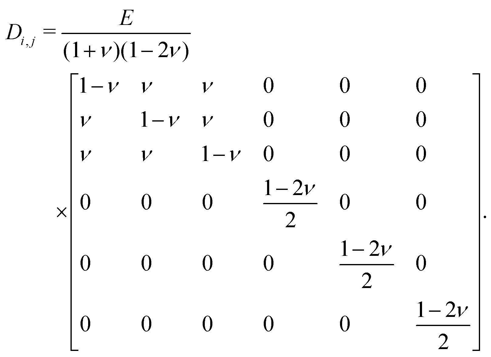 | (2) |
If we want to know the deformation due to thermal expansion and ignore the shear components in Hooke's law, we get:
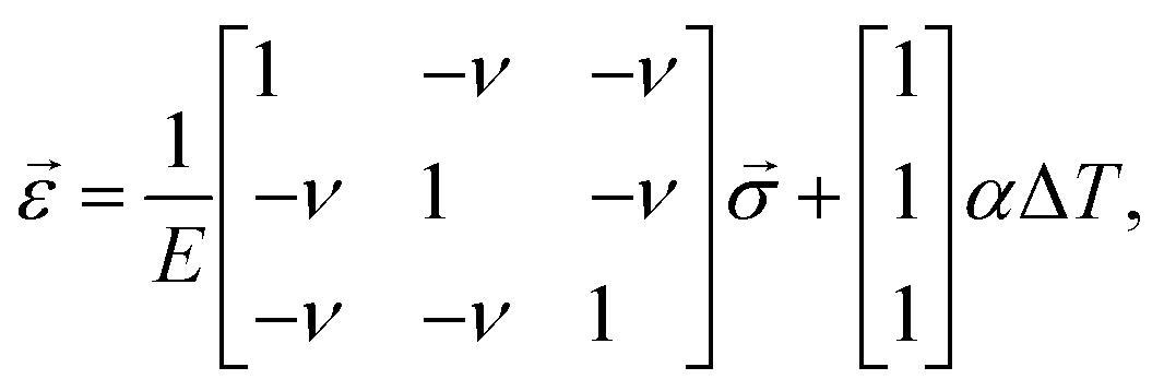 | (3) |
For infinitesimally shallow cavities, we can analytically obtain the strain using Hooke's law (eqn (3)) and subsequently the surface deformation Δh, which is caused by the PDMS shrinkage. Adding boundary conditions for an isotropic material with a fixed bottom and side walls (εx=y = 0) and a free top surface (σz = 0), the in-plane stress becomes
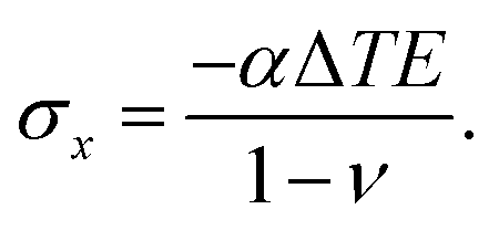 | (4) |
Substituting eqn (4) into the strain in the transverse direction εz, we get:
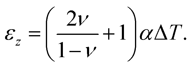 | (5) |
The surface deformation Δh from the PDMS shrinkage in a cavity with depth H is then:
| Δh = εzH. | (6) |
For finite cavities, the analytical estimate is less trivial. Hence, we used finite element method (FEM) simulations to predict different cavity depths and temperatures, using eqn (6) to verify our model.
For a hypothetical infinitely deep cavity, we have a negative pressure Δp in the material close to the bottom of the cavity, depending on the bulk modulus K, and the volume shrinkage ΔV/V:
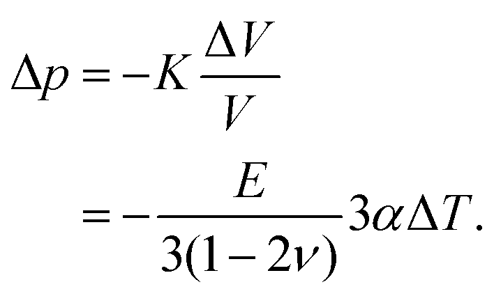 | (7) |
To account for an additional shrinkage ε0 due to the temperature ramp in the curing protocol and for the polymerisation shrinkage, we could replace α with  .
.
2.3 Finite element method (FEM) simulations
We performed the FEM simulation using COMSOL Multiphysics as per the method described in Section 2.1. Therefore, we chose the 2-D axisymmetric structural mechanics module using solid mechanics with a linear elastic material model: thermal expansion. The geometry and the used mesh with corner refinement at the edge of the cavity are illustrated in Fig. 1. To rule out a possible mesh dependency at the edge of the cavity, we also simulated different mesh sizes and chamfers and fillets with different radii and found rapid convergence with decreasing mesh size or decreasing curvature radius. The boundary conditions were set as: a roller constraint at the bottom and a free boundary on the sidewalls and the top surface. As we vary the depth of the cavities from shallow to very deep, the resulting surface deformation becomes relatively large such that nonlinear effects cannot be neglected. Thus, geometric nonlinearities were taken into account for a precise result. We used four nested parametric sweeps of different cavity depth Hn, curing temperature T, Poisson's ratio ν and linear coefficient of thermal expansion α to obtain an interpolation fHn,T(ν, α) over ν and α for each cavity depth and temperature.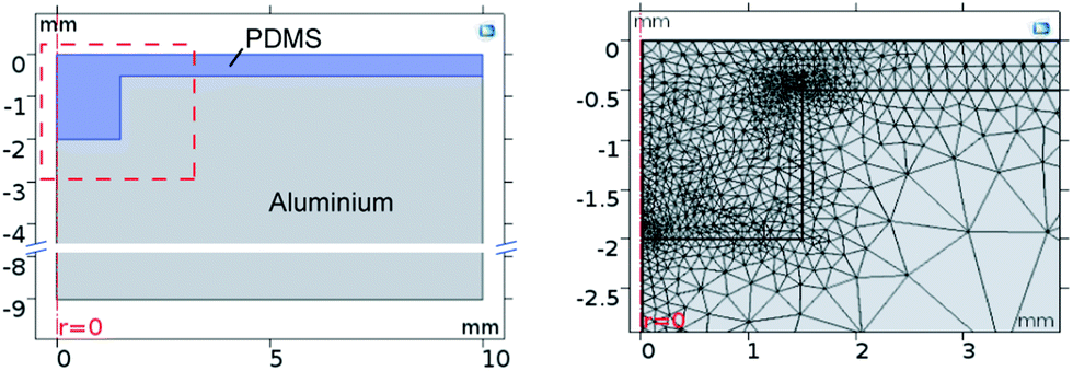 | ||
| Fig. 1 Left: Cross section of the FEM model. Right: Mesh of the FEM model in the region near the cavity (the red box in the left image). | ||
The analytical estimate from eqn (5) for the strain in a finite cavity differs from the simulation with equivalent boundaries by 1.12% and 3.63% at aspect ratios of 1![[thin space (1/6-em)]](https://www.rsc.org/images/entities/char_2009.gif) :10 and 1:20, respectively, and the negative pressure of the analytical estimate in eqn (7) deviates by 0.12% and 0.15% for the same aspect ratios. Hence, we can assume that the simulation is reliable.
:10 and 1:20, respectively, and the negative pressure of the analytical estimate in eqn (7) deviates by 0.12% and 0.15% for the same aspect ratios. Hence, we can assume that the simulation is reliable.
3 Experimental procedure
We investigated two commonly used types of PDMS: Sylgard 184 and Sylgard 182, from Dow Chemical Company (formerly DowCorning), which differ in their viscosity, shore hardness and curing time. First, we prepared them as recommended in the data sheets.23,24 The liquid two-part silicone elastomer kit consists of a pre-polymer base (part A) and a cross-linking curing agent (part B), which need to be mixed thoroughly in a 10:1 ratio. After mixing, the PDMS was degassed in a vacuum desiccator at a pressure below 30 mbar for at least 15 min (until the mixture shows no more air bubbles) and was filled into an aluminium substrate, where it was degassed again for at least 30 min. We fabricated the aluminium cavities using precise CNC milling, as illustrated schematically in Fig. 2, top. The substrate has four cavities each with different depths: 0.5 mm, 0.75 mm, 1 mm and 1.5 mm. The diameter of all cavities is kept constant at d = 3 mm, and we add a spacer with thickness t = 0.5 mm. After pouring the liquid PDMS into the cavities and degassing, we carefully arranged a silane coated glass slide on top and placed the device directly into a mechanical press, which was preheated at different temperatures (see Table 1). We then applied a force of at least 1 kN to prevent motion or deformation of the glass slide. While the still liquid PDMS expands, the excess material is pressed out of the substrate via the spacers.
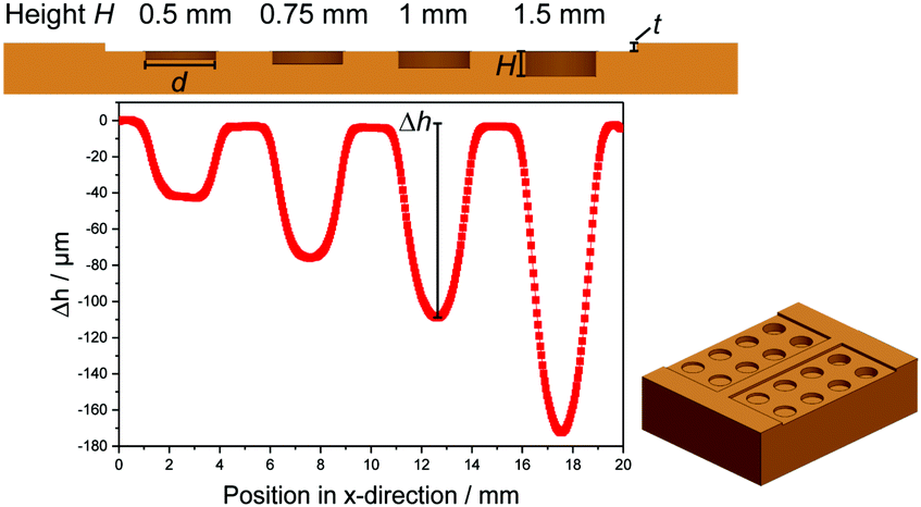 | ||
| Fig. 2 Top: Cross-section of the aluminium substrate with different cavity depths. Bottom: Measured profile of the generated PDMS (Sylgard 184) surface deformation at 120 °C at the corresponding position. Bottom right: Schematic illustration of the whole milled aluminium substrate. | ||
| PDMS | Start (°C) | Ramp (min) | End (°C) | Curing (h) |
|---|---|---|---|---|
| S184 | 50 | 60 | 60 | 6 |
| 65 | 18 | 75 | 2.5 | |
| 80 | 6 | 90 | 1 | |
| 105 | 0 | 105 | 0.5 | |
| 120 | 0 | 120 | 0.3 | |
| 135 | 0 | 135 | 0.2 | |
| S182 | 50 | 120 | 60 | 11.2 |
| 65 | 45 | 75 | 4.7 | |
| 80 | 15 | 90 | 2 | |
| 95 | 6 | 105 | 1 | |
| 120 | 0 | 120 | 0.6 | |
| 135 | 0 | 135 | 0.4 |
After curing, we released the pressure and removed the glass slide, such that the substrate can cool down to room temperature. Doing so, the material shrinks and a small surface deformation is formed.
We measured the surface deformations using an optical surface scanning profilometer with a chromatic confocal sensor CS-MG-CL2 from Polytec GmbH. It has a lateral resolution of 1.7 μm with a working range of 400 μm and an axial resolution of 2.7 nm. After leveling the surface profile using the measured vertical positions between the cavities, we evaluated the minimum of each surface deformation manually, as shown in Fig. 2. A three dimensional profilometer measurement of Sylgard 184 at 120 °C is illustrated in Fig. 3.
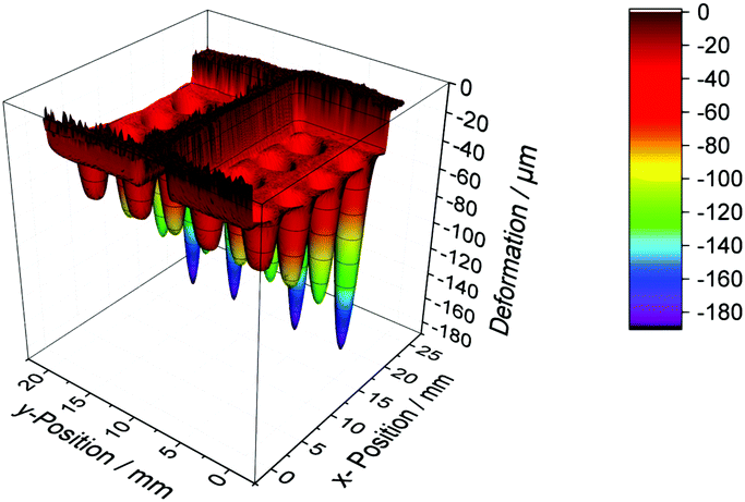 | ||
| Fig. 3 Measured 3-D profile of the generated PDMS (Sylgard 184) surface deformation at 120 °C. | ||
The temperature protocol was found experimentally, guided by the curing time, and is summarised in Table 1. The measurements were done with four different cavity depths, with each done for at least four cavities, at six different temperatures, to generate a statistically significant measurement sample.
4 Data evaluation
To relate the measurements to the simulation, we had to relate one quantity, the maximum surface deformation Δh, measured at different cavity depths, to two quantities, ν and α. Equating the measured Δh to the interpolation fHn,T(ν, α) leaves us with one unknown degree of freedom, i.e., with a line in the space (α, ν) for each cavity depth Hn. The intersection of these lines of different cavities then gives us the predicted value of ν and α. To take into account the measurement uncertainty, we assumed a Gaussian probability distribution W of the surface deformation Δh for each cavity depth Hn at a constant temperature T: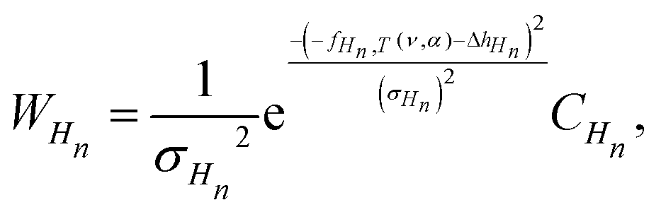 | (8) |
 | (9) |
The distributions for different depths at a constant temperature are shown in Fig. 4 (left) at 60 °C for all four cavity depths. The distributions are then multiplied to get a total probability distribution of the overall measurement result for ν and α, as illustrated in Fig. 4 (right). We see that the Poisson's ratio and the coefficient of thermal expansion for one temperature correlate and have dependent uncertainties. To obtain independent uncertainty values, we integrated one variable to obtain an independent value for the other variable.
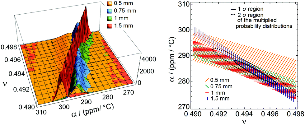 | ||
| Fig. 4 Data evaluation in (α, ν) space using Mathematica. Left: Probability distribution for different cavity depths. Right: 1σ probability region for different cavities and the 1 and 2σ regions of the multiplied probability distributions of all different cavity depths. | ||
5 Results
The surface deformations for both materials at different cavity depths and temperatures are summarised in Fig. 5. As expected, deep cavity depths lead to a relatively large surface deformation. We optically verified that there is no delamination of the PDMS from the aluminium mould inside the cavities. In Fig. 4, we see that the probability distributions for the different cavity depths cross approximately at a single point, which validates our measurement method.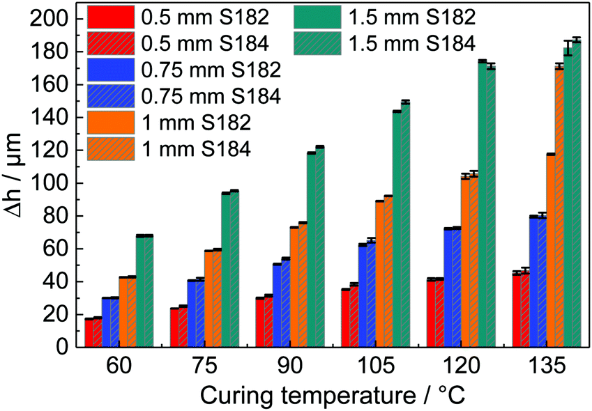 | ||
| Fig. 5 Measurement results: Surface deformation Δh at different cavity depths for both Sylgard 184 (S184) and Sylgard 182 (S182) at different curing temperatures. The error bars indicate the sample over at least four cavities. | ||
The heat transfer in the setup was simulated to ensure the drainage of the liquid PDMS, as illustrated in Fig. 6, using the 1.5 mm deep mould. The temperature at the center of the PDMS reaches 90% in 3.97 s for Sylgard 184 and 6.98 s for Sylgard 182, which is in both cases well below the curing time.
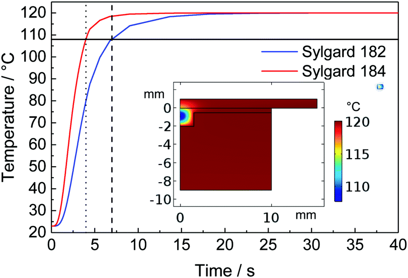 | ||
| Fig. 6 Simulated heat transfer in the complete setup for both PDMS types with indications at 90% of the final temperature. Inset: Simulation of Sylgard 184 at 90% of the final temperature. | ||
In our most extreme case of the strain (relative volume change), at a cavity depth of 1.5 mm and a curing temperature of 135 °C, the maximum strain is 10.83%. The volume with a strain of more than 5% accounts for less than 3.8% of the overall volume change. Hence, we can conclude that the result is dominated by small strains, where the possible nonlinear deformation near the edge is negligible. In comparison to standard tensile tests, which usually measure strains around 10% going up to strain values of 40%,3,16 our results are dominated by strains in the range from 1% to 2.35%.
The Poisson's ratio for Sylgard 184 and Sylgard 182 at six different temperatures is shown in Fig. 7. The shaded areas show the error of the mean values. We can find an approximately constant Poisson's ratio for both materials. Averaging the overall curing temperatures, the Poisson's ratio for Sylgard 184 is ν = 0.4950 ± 0.0010 and for Sylgard 182, it is ν = 0.4974 ± 0.0006. Comparing our values to the literature, we find a good agreement but a more precise result. Roman11 found a value of ν = 0.47 ± 0.028, which is in the same range as our result and Pritchard et al.15 measured a Poisson's ratio of ν = 0.5 ± 0.002 with half of the measurements above ν = 0.5. Most of the other values of the Poisson's ratio found in the literature are estimates that are close to 0.5 without an exact value, e.g. Schneider et al.: ν = 0.49,6 Du et al.: ν = 0.499,7 Studer et al. and Sasoglu et al.: ν = 0.4512,13 or Johnston et al.: ν = 0.499.16
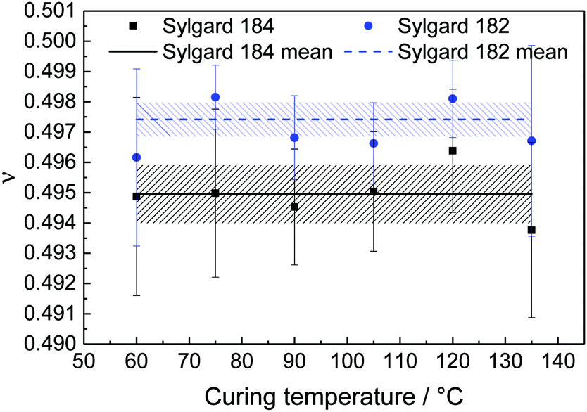 | ||
| Fig. 7 Poisson's ratio, ν, for Sylgard 184 and Sylgard 182 at six different temperatures with the obtained mean value. The shaded areas show the error of the mean values. | ||
We further fitted the coefficient of thermal expansion 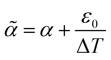 , which includes a contribution due to the polymerisation shrinkage and the temperature ramp ε0, to the measurement results, and found that ε0 is in the order of polymerisation shrinkage around 0.1%, which is clearly smaller than the measurement uncertainty and was thus further neglected. In Fig. 8, we find an approximately linear decrease in the coefficient of thermal expansion with increasing curing temperature. For Sylgard 184, we extrapolated the coefficient of thermal expansion at 25 °C from our measurement to be (309.63 ± 6.91) ppm °C−1, which is approximately 9% less than the value given in the data sheet (340 ppm °C−1).23 It decreases to a coefficient of (−0.65 ± 0.07) ppm °C−2. For Sylgard 182, it is (289.55 ± 4.44) ppm °C−1, which is approximately 11% less than the data sheet value (325 ppm °C−1),24 and it decreases to (−0.51 ± 0.05) ppm °C−2.
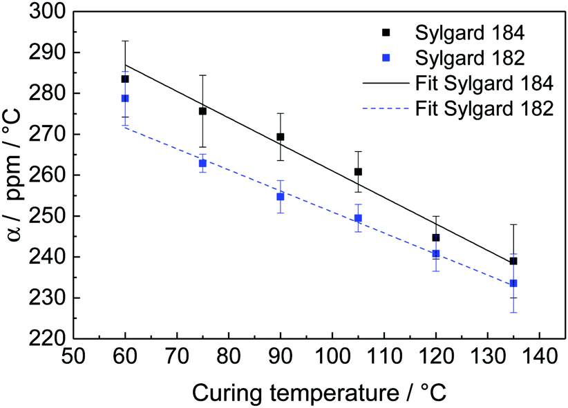 | ||
| Fig. 8 Coefficient of thermal expansion, α, for Sylgard 184 and Sylgard 182 at six different temperatures with linear fits. | ||
6 Conclusions
We found a new method to accurately determine the Poisson's ratio using the thermal expansion properties of PDMS and an optical surface scanning device. The Poisson's ratio for Sylgard 184 is ν = 0.4950 ± 0.0010 and for Sylgard 182, it is ν = 0.4974 ± 0.0006. The results are in good agreement with the literature.6–9,11,14,16 In addition to the Poisson's ratio, we also found the coefficient of thermal expansion and observed a linear decrease with increasing temperature. For Sylgard 184, we found an extrapolated value of (309.63 ± 6.91) ppm °C−1 at 25 °C with a decreasing trend of (−0.65 ± 0.07) ppm °C−2 and for Sylgard 182, we found (289.55 ± 4.44) ppm °C−1 and (−0.51 ± 0.05) ppm °C−2, respectively.One main advantage of this new method is that it only needs a profilometer, FEM simulations and numerical mathematics to determine the Poisson's ratio, without any additional tensile testing setup or advanced tracking methods, in particular since tracking the transverse deformation of elastomers to such an accuracy is non-trivial. With our method, we can measure in a very small strain regime compared to standard tensile tests. We assume that our method can also be used for other polymers that are produced by curing from a liquid. In these cases, one needs to take into account the possible absorption of humidity, which may lead to swelling. PDMS, however, does not show a significant swelling with a relative weight change of 0.03 ± 0.02%.25
Conflicts of interest
There are no conflicts to declare.Acknowledgements
We thank Matthew F. Berwind and Chris Eberl for helpful discussions on different aspects of elastomers and their mechanical testing methods. This work was supported by the BrainLinks-BrainTools Cluster of Excellence funded by the German Research Foundation (DFG, grant no. EXC 1086).References
- J. M. Ng, I. Gitlin, A. D. Stroock and G. M. Whitesides, Electrophoresis, 2002, 23, 3461–3473 CrossRef CAS PubMed.
- J. Friend and L. Yeo, Biomicrofluidics, 2010, 4, 1–5 Search PubMed.
- F. Schneider, T. Fellner, J. Wilde and U. Wallrabe, J. Micromech. Microeng., 2008, 18, 1–9 CrossRef.
- J. E. Mark, Polymer Data Handbook, Oxford University Press, New York, 2nd edn, 2009, p. 1250 Search PubMed.
- G. Ouyang, K. Wang, L. Henriksen, M. Akram and X. Chen, Sens. Actuators, A, 2010, 158, 313–319 CrossRef CAS.
- F. Schneider, J. Draheim, C. Müller and U. Wallrabe, Sens. Actuators, A, 2009, 154, 316–321 CrossRef CAS.
- P. Du, I. K. Lin, H. Lu and X. Zhang, J. Micromech. Microeng., 2010, 20, 1–13 Search PubMed.
- J. Brunne and U. Wallrabe, Opt. Lett., 2013, 38, 1939–1941 CrossRef CAS PubMed.
- B. Wang and S. Krause, Macromolecules, 1987, 20, 2201–2208 CrossRef CAS.
- K. Hosokawa, K. Hanada and R. Maeda, J. Micromech. Microeng., 2002, 12, 1–6 CrossRef CAS.
- P. A. Roman, PhD thesis, Oregon Health & Science University, 2004.
- V. Studer, G. Hang, A. Pandolfi, M. Ortiz, W. F. Anderson and S. R. Quake, J. Appl. Phys., 2004, 95, 393–398 CrossRef CAS.
- F. M. Sasoglu, A. J. Bohl and B. E. Layton, J. Micromech. Microeng., 2007, 17, 623–632 CrossRef CAS.
- D. W. Inglis, Biomicrofluidics, 2010, 4, 1–8 Search PubMed.
- R. H. Pritchard, P. Lava, D. Debruyne and E. M. Terentjev, Soft Matter, 2013, 9, 6011–6198 RSC.
- I. D. Johnston, D. K. McCluskey, C. K. L. Tan and M. C. Tracey, J. Micromech. Microeng., 2014, 24, 1–7 CrossRef.
- L. D. Landau and E. M. Lifschitz, Theory of elasticity, Butterworth-Heinemann, Oxford, 3rd edn, vol. 7, 1999 Search PubMed.
- H. Jin and J. L. Lewis, J. Biomech. Eng., 2004, 126, 138–145 CrossRef PubMed.
- I. Levental, K. R. Levental, E. A. Klein, R. Assoian, R. T. Miller, R. G. Wells and P. A. Janmey, J. Phys.: Condens. Matter, 2010, 22, 1–9 CrossRef PubMed.
- M. R. VanLandingham, N.-K. Chang, P. L. Drzal, C. C. White and S.-H. Chang, J. Polym. Sci., Part B: Polym. Phys., 2005, 43, 1794–1811 CrossRef CAS.
- Z. Wang, A. A. Volinsky and N. D. Gallant, J. Appl. Polym. Sci., 2015, 132, 1–7 Search PubMed.
- J. K. Deuschle, G. Buerki, H. M. Deuschle, S. Enders, J. Michler and E. Arzt, Acta Mater., 2008, 56, 4390–4401 CrossRef CAS.
- The Dow Chemical Company, Technical Data Sheet Sylgard 184, Form No. 11-3184-01 C, 2018, https://consumer.dow.com/content/dam/dcc/documents/en-us/productdatasheet/11/11-31/11-3184-sylgard-184-elastomer.pdf, accessed on 09/10/2018.
- The Dow Chemical Company, Technical Data Sheet Sylgard 182, Form No. 11-1251-01 B, 2018, https://consumer.dow.com/content/dam/dcc/documents/en-us/productdatasheet/11/11-12/11-1251-01-sylgard-182-silicone-elastomer.pdf, accessed on 09/10/2018.
- J. Draheim, PhD thesis, University of Freiburg, Freiburg, 2011.
| This journal is © The Royal Society of Chemistry 2019 |