Rapidly tunable and highly reversible bio-inspired dry adhesion for transfer printing in air and a vacuum†
Changhong
Linghu
 a,
Chengjun
Wang
a,
Nuo
Cen
b,
Jiaming
Wu
c,
Zhengfeng
Lai
d and
Jizhou
Song
a,
Chengjun
Wang
a,
Nuo
Cen
b,
Jiaming
Wu
c,
Zhengfeng
Lai
d and
Jizhou
Song
 *a
*a
aDepartment of Engineering Mechanics, Soft Matter Research Center, and Key Laboratory of Soft Machines and Smart Devices of Zhejiang Province, Zhejiang University, Hangzhou 310027, China. E-mail: jzsong@zju.edu.cn
bFaculty of Engineering, Zhejiang University, Hangzhou 310027, China
cDepartment of Mechatronic Engineering, Zhejiang University, Hangzhou 310027, China
dDepartment of Information Science and Electronic Engineering, Zhejiang University, Hangzhou 310027, China
First published on 5th November 2018
Abstract
Tunable and reversible dry adhesion has attracted much attention in academia and industry due to its wide applications ranging from releasable joints to stamps for transfer printing. Here, a simple yet robust magnetically actuated, aphid-inspired design of an elastomeric surface that provides rapidly tunable and highly reversible adhesion strength is reported. The magnetically actuated adhesive features open reservoirs filled with magnetic particles and encapsulated by a thin surface membrane, which can be deformed in a controlled manner via the magnetic field, thus, to tune the adhesion. The combination of the rate dependent effect and magnetic actuation of the thin surface membrane offers continuously tunable adhesion with a great switchability and a quick response. Experimental and theoretical studies reveal the underlying physics and provide design guidelines to optimize geometries for the broad control of adhesion. Demonstrations of this concept in stamps for transfer printing of silicon wafers in air and in a vacuum with a selective and programmable mode illustrate the capabilities for deterministic assembly and the potential in the semiconductor industry.
1. Introduction
Tunable and reversible adhesion is desired in many existing and envisioned systems including medical tape,1–5 climbing robotics,6–10 grippers for precision industries,11–16 and stamps for deterministic assembly by transfer printing.17–23 Such smart adhesion can be easily found in animals like geckos, beetles, flies and ants, where the tunable and reversible adhesion enables them to attach and detach quickly to surfaces of varying materials and topographies for fast locomotion, prey capturing and defense against predators. The adhesive pads of these animals feature fibrillar surface structures, often combined with secretions.24–27 One of the most efficient adhesion systems is found in geckos, which is a dry system without relying on adhesion enhancing secretions. It offers surface contamination free,11 environmentally-friendly, and cost and energy saving advantages, as well as good compliance for intimate contact, thus, strong adhesion with various substrates, etc. Besides the outstanding adhesive features, gecko adhesion also offers quick and easy detachment by controlling the anisotropy of fibrillary surface structures.10,28 The amazing adhesion of the gecko has inspired very active research1,3,6,7,11,29,30 over the last decade and shows promising potential in next generation green manufacturing,13 especially in the cases of reduced pressure in the semiconductor industry, or in chemical and physical vapor deposition processes, where transfer printing of clean and fragile thin objects (e.g., silicon wafers or glass plates) is required.11,13,31 The gecko-inspired surface has enabled several transfer printing systems to be developed for applications in novel forms of electronics and opto-electronics.32–34 Although the gecko-inspired surface provides an effective path to a strong and reversible dry adhesive, the fabrication of the fibrillar surface structures usually requires micro/nanofabrication equipment, which is not commonly available, and the fabrication process is quite complicated and costly.35A different strategy, where the adhesion is modulated by changing the topography of a smooth adhesive pad analogous to the aphid pulvilli, has drawn attention due to its simplicity and efficiency. Although previously reported aphid-inspired adhesive studies provide significant utility in this context,12,36,37 they are all inflation based, requiring careful designs and complex fabrication of microchannels, which impedes their applications in a vacuum. Moreover, the requirement for the connection of air pipes to the adhesive system further limits their practical applications due to the inherent energy-consuming and noisy features. Here, a simple yet robust magnetically actuated, aphid-inspired design of an elastomeric surface that provides rapidly tunable and highly reversible adhesion strength is reported. This construct eliminates the direct connection to outer equipment and yields continuously tunable adhesion with a great switchability and a quick response. Systematic experimental and theoretical studies reveal the fundamental aspects of the design, fabrication and operation, and also provide quantitative design guidelines for future scaled systems. We demonstrate this concept in stamps for transfer printing of silicon wafers in air and in a vacuum to illustrate the capabilities for deterministic assembly and the potential in the semiconductor industry. Besides, we show that the stamp reserviors can be individually addressed by a localized magnetic field provided by a cone-shaped electromagnet, thus enabling selective and patterned printing.
2. Experimental
Fabrication of the aphid-inspired adhesive
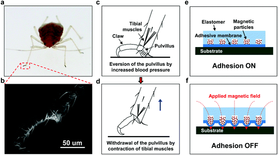
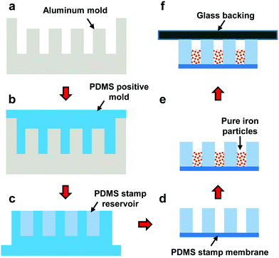
Fig. 1a–d show the adhesion system and release strategy of an aphid clinging to a flat surface. When adhering to a smooth surface, the aphid's pulvillus is everted by increased blood pressure, which increases the contact area and hence the adhesion strength. Upon releasing from the surface, the pulvillus is withdrawn by the retraction of tibial muscles, which demolishes the contact area and leads to low adhesion. Fig. 1e and f illustrate the design of the magnetically actuated, aphid-inspired adhesive (also called the stamp). The bio-inspired adhesive features open reservoirs in an elastomer stamp, which are filled with magnetic particles and encapsulated by a thin surface membrane. Sufficient adhesion for attachment to a substrate relies on the flat surface membrane, which is referred to as the adhesion ON state (Fig. 1e). While exposed to a gradient magnetic field, the magnetic particles are magnetized and push the thin surface membrane to bulge around the interface upon the release of the elastomer from the substrate. As the release continues, the membrane starts to peel at the outer perimeter and propagates to the center, thereby decreasing the contact with the substrate, reducing the interfacial adhesion and facilitating the interfacial delamination. We refer to the state exposed to the gradient magnetic field as the adhesion OFF state (Fig. 1f). This magnetically actuated aphid-inspired design of an elastomeric surface is of simple configuration and can provide an adhesion switch between a strong (i.e., adhesion ON) state and a weak (i.e., adhesion OFF) state in a robust, rapid, and repeatable manner.The fabrication process of the magnet-actuated, aphid-inspired adhesive is illustrated in Fig. 2. The preparation of the stamp reservoir involved a series of molding and demolding steps (Fig. 2a–c). An aluminum mold (Fig. S1a, ESI†) was first fabricated using CNC (computer numerical control) machining. The stamp reservoir was then generated by a double replica molding process utilizing PDMS (Sylgard 184, Dow Corning). The liquid PDMS mixture (10![[thin space (1/6-em)]](https://www.rsc.org/images/entities/char_2009.gif) :
:![[thin space (1/6-em)]](https://www.rsc.org/images/entities/char_2009.gif) 1 base to curing agent ratio) was poured into the aluminium mold, degassed in a vacuum chamber for 30 min, and then cured in an oven at 65 °C for 3 h. After demolding, a PDMS positive mold (Fig. S1b, ESI†) was generated and exposed to a UV/ozone environment for 30 min to form a silane non-stick layer on the surface. Then, the liquid PDMS mixture (10
1 base to curing agent ratio) was poured into the aluminium mold, degassed in a vacuum chamber for 30 min, and then cured in an oven at 65 °C for 3 h. After demolding, a PDMS positive mold (Fig. S1b, ESI†) was generated and exposed to a UV/ozone environment for 30 min to form a silane non-stick layer on the surface. Then, the liquid PDMS mixture (10![[thin space (1/6-em)]](https://www.rsc.org/images/entities/char_2009.gif) :
:![[thin space (1/6-em)]](https://www.rsc.org/images/entities/char_2009.gif) 1 base to curing agent ratio) was poured into the positive PDMS mold, degassed in a vacuum chamber for 30 min, and then cured in an oven at 75 °C for 4 h. Finally, the stamp reservoir was demolded from the positive PDMS mold.
1 base to curing agent ratio) was poured into the positive PDMS mold, degassed in a vacuum chamber for 30 min, and then cured in an oven at 75 °C for 4 h. Finally, the stamp reservoir was demolded from the positive PDMS mold.
The stamp membrane was fabricated in a mold composed of two glass plates (100 mm × 80 mm × 4 mm) separated by an acrylic spacer with a thickness of 1.8 mm. First, the spacer was glued onto one glass plate to form a reservoir. The reservoir was then filled with liquid PDMS mixture (10![[thin space (1/6-em)]](https://www.rsc.org/images/entities/char_2009.gif) :
:![[thin space (1/6-em)]](https://www.rsc.org/images/entities/char_2009.gif) 1 base to curing agent ratio) and covered by the other glass plate. The membrane mold containing uncured PDMS mixture was degassed in a vacuum chamber for 30 min, and then cured in an oven at 75 °C for 4 h.
1 base to curing agent ratio) and covered by the other glass plate. The membrane mold containing uncured PDMS mixture was degassed in a vacuum chamber for 30 min, and then cured in an oven at 75 °C for 4 h.
Then, the bottom surfaces of the stamp reservoir and the stamp membrane were activated using plasma etching techniques. The two activated surfaces were then brought into contact and heated in an oven at 80 °C for 10 min to form a chemically bonded interface. Pressure was applied on top of the stamp membrane to ensure intimate contact during the heating process. The stamp reservoir attached to the stamp membrane was then filled with pure iron particles and sealed with a glass plate after activation of the glass and the PDMS reservoir top surface using plasma etching techniques.
A unit cell stamp and a 5 × 5 array stamp were fabricated for the adhesion characterization, demonstrations in transfer printing of silicon wafers both in air and in a vacuum, and demonstrations of the capabilities of the selective and programmable printing, separately.
Adhesion measurements
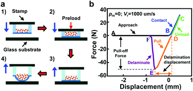
To characterize the performance of the magnetically actuated aphid-inspired adhesive, vertical pull tests36,38 were carried out under various magnetic pressures and retraction speeds for a stamp/glass interface. The measurement setup (Fig. S2, ESI†) consists of a materials testing system (Model 5944, INSTRON), a two-axes manual tip/tilt platform and a permanent magnet with the maximum magnetic field density and the gradient of 325.9 kA m−1 and 9.46 MA m−2, respectively. The resolution of the load cell is 2 mN. The pull test process is illustrated in Fig. 3a. The stamp approaches and contacts with a clean glass substrate (attached to the load cell) at a fixed speed of 100 μm s−1. A proper preload, determined by eliminating its influence on the pull-off force (Fig. S3, ESI†), is applied to ensure intimate coupling between the stamp and the glass. After a relaxation of 20 s, the stamp is retracted at a fixed speed (Vr). The pull-off force (namely, the maximum pull force) is obtained from the force–displacement curve (Fig. 3b) for the given magnetic pressure and retraction speed. Distributing the pull-off force over the interfacial contact area gives the adhesion strength.3. Results and discussion
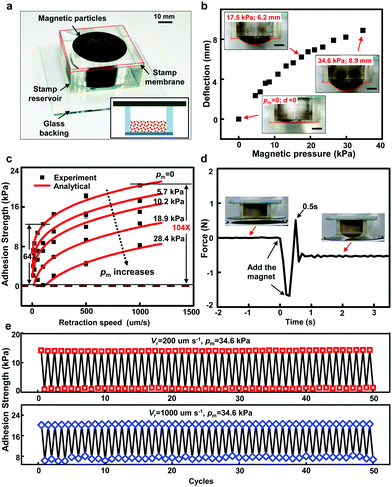
Fig. 4a provides an optical image of a magnetically actuated aphid-inspired adhesive with a unit cell, which incorporates a circular reservoir (20 mm in radius and 20 mm in depth) in a square elastomer stamp (50 mm × 50 mm × 20 mm) created using a double replica molding method (see Fig. 2) from PDMS. After filling the reservoir with magnetic particles (pure iron particles with 250 μm radius), a thin surface membrane (50 mm × 50 mm × 1.8 mm, also called the stamp membrane) is chemically bonded to the elastomer stamp for encapsulation. The aphid-inspired stamp is finally bonded to a glass backing (80 mm × 80 mm × 2 mm) for sealing and easy handling.When exposed to a gradient magnetic field, the pure iron particles are magnetized and the resulting magnetic force presses the stamp membrane and causes the membrane to bulge. The deflection of the stamp membrane can be controlled, as shown in Fig. 4b, by the magnetic field intensity and gradient. To demonstrate the underlying mechanical nature of the modulation mechanism, the magnetic pressure pm (i.e., the average magnetic force on the suspended stamp membrane from the magnetic particles) rather than the magnetic field intensity and gradient is measured and provided here. Without the magnetic field, the stamp membrane remains flat, which indicates that the influence of the gravity of the magnetic particles on the membrane deformation is negligible. With the magnetic field, the stamp membrane deforms into a hemispherical geometry, which is analogous to the configuration of a circular plate under uniformly distributed pressure. As the magnetic pressure increases, the stamp membrane deflection increases. For example, the membrane deflection at the center of the circular reservoir can increase to 8.9 mm (about half of the reservoir radius) when the magnetic pressure is 33 kPa. This magnetic force-dependent membrane deflection enables the magnetically actuated adhesion with great switchablilty, rapid tunability, and high reversibility.
Fig. 4c shows the measured adhesion strength (black dots) under various magnetic pressures as a function of the retraction speed from 10 μm s−1 to 1000 μm s−1. As expected, the adhesion strength is rate-dependent39,40 and increases with the retraction speed due to the viscosity effect of the PDMS material. More importantly, the magnetic pressure moves the adhesion strength–retraction speed curve downwards, which indicates that the adhesion strength is strongly magnetic pressure-dependent. By modulating the magnetic field intensity and gradient via the change of the distance between the permanent magnet and the interface, hence the magnetic pressure, the adhesion strength can be continuously tuned to specific values. For the measured adhesion strengths, the adhesion switchability, defined by the maximum adhesion strength over the minimum adhesion strength, of about 64× is realized by the modulation of the magnetic field from 0 to 28.4 kPa at a given retraction speed of Vr = 100 μm s−1. Combined with the retraction speed modulation, a 104× reduction of adhesion strength can be realized within the measurement capabilities of the experiments. For the elevated magnetic pressures with a lower retraction speed, the adhesion strength is reduced to nearly zero, which yields an infinite switchability and is below the measurement capabilities. The infinite switchability can be well demonstrated by the case with Vr = 20 μm s−1 and pm = 18.9 kPa, as shown in Fig. S4, ESI,† where the pull force remains positive such that the net force that the stamp applies on the ink is pressure (instead of an adhesion), which indicates a nearly zero adhesion, enabling the non-contact mode41 in transfer printing as demonstrated subsequently, where the silicon wafer remains non-contacted with the receiver substrate before the complete release occurs. The result reported here is comparable to the switchability of the most sophisticated stamp reported so far with 1000×42 or even infinity.41
Fig. 4d shows the force acting on the receiver substrate versus time during the magnet-actuated release process of a silicon wafer from the stamp in a non-contact mode of transfer printing. The silicon wafer drops onto the substrate in less than 0.5 s, comparable to the instantly switchable adhesion reported in the literature.43 It should be noted that the recorded force–time curve also includes the time to place the permanent magnet under the receiver substrate, the actual release process is even faster, in nearly 100 ms (see Movie S1, ESI†). The quick release process is due to the fast response of the magnetic particles to the applied magnetic field, which plays a key role in yielding a rapidly tunable adhesion, thus enhancing the speed and efficiency of transfer printing.
The reversibility and repeatability of the magnetically actuated adhesive are shown in Fig. 4e. The switchable adhesions with the magnetic field modulation for 50 cycles at both high (1000 μm s−1) and low retraction speeds (200 μm s−1) demonstrate the high performance of the magnet-controlled stamp. For example, for the high retraction speed of 1000 μm s−1, the adhesion strength is tuned from a high value of 20.5 kPa to a low value of 7.3 kPa with the increase of the magnetic pressure from 0 to 34.6 kPa. The high and low adhesion strengths remain almost unchanged during the 50 cycles, which indicates the high reversibility and repeatability of the magnetically actuated adhesive.
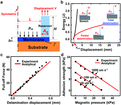
An analytical mechanics model was developed to provide insights into the delamination process of the stamp. The key geometric parameters of the magnetically actuated stamp and the stamp/glass substrate interface are shown in Fig. 5a. A displacement V is applied at the top surface of the bulk region of the stamp through the glass backing. The magnetic pressure pm on the stamp membrane is assumed to be uniformly distributed. The analytical model treats the system as a double clamped beam subjected to the displacement V and the magnetic pressure pm, which is similar to the model previously reported for an inflatable stamp36 but different in geometry and loading conditions.
During the retraction process, the stamp remains in contact with the substrate for a small displacement V and only the reservoir is stretched with the potential energy given by
 | (1) |
As the displacement V increases, the membrane starts to delaminate from the substrate with l denoting the delamination length, and the potential energy of the system is obtained as
 | (2) |
 | (3) |
| Vd = Vcrit − pmπL2H/[4ERAR(L + AR)] | (4) |
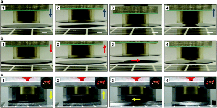
The transfer printing of silicon wafers (4 inches in diameter and 1 mm in thickness) onto a ceramic substrate in air and vacuum was demonstrated to illustrate the capabilities of the magnetically actuated aphid-inspired adhesive. Although the retraction speed has been used to control the adhesion for transfer printing,39,40 it fails to release the silicon wafer even under a slow retraction speed (100 μm s−1), as shown in Movie S1, ESI.† The current magnetically actuated bio-inspired adhesive involves active control of the adhesion via the magnetic field and enables successful transfer printing in both contact and non-contact modes (see Movie S1, ESI†) in a reliable manner. Fig. 6a and b present optical images of the system in various states of the contact and non-contact transfer printing processes, respectively. The release of the silicon wafer from the stamp is very quick and can be completed within 0.5 s. The high manipulation efficiency and alignment accuracy are demonstrated in the transfer printing of a stack of silicon wafers in air (see Movie S2, ESI†). In order to place the material to be transferred in the correct position, the gap between the ink and the receiver should be smaller than the maximum deflection of the deformed stamp membrane during the release process. Fig. 6c shows the capability of transfer printing using the magnetically actuated bio-inspired stamp in a vacuum with a vacuum degree of 92 kPa under atmosphere pressure. Movie S3, ESI† records the whole process of the transfer printing of a stack of silicon wafers in a vacuum. This feature ensures its great potential in the semiconductor and display industries or in chemical and physical vapor deposition processes, where transfer printing of clean and fragile thin objects is required at reduced pressure that is difficult to operate with suction-based systems.
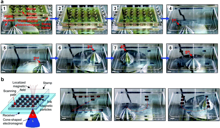
When manipulated with a localized magnetic field, the reservoirs can be individually actuated, thus providing the potential for selective printing. Fig. 7(a1–a4) shows the printing process of a selected platelet out of a 5 × 5 array (Fig. S6, ESI†) onto the PDMS receiver substrate. All the reservoirs in the stamp are inked with square silicon platelets (12 mm × 12 mm × 0.5 mm). The localized magnetic field is provided by a home-made cone-shaped magnetic pole (Fig. S7, ESI†). The unique assembly capabilities are demonstrated by the sequential selective printing of five silicon platelets out of the 5 × 5 array (Fig. 7a4–a8 and Movie S4, ESI†) onto a PDMS substrate. Besides, with the scanning of the localized magnetic field enabled by an automated platform (Fig. 7b and Fig. S8, ESI†), the printed pattern can be programmed and deployed rapidly, as demonstrated in Fig. 7b and Movie S5, ESI,† where the letters ‘ZJU’ as the abbreviation of ‘Zhejiang University’ are patterned onto PDMS substrates. The selective printing combined with the automated platform provides great opportunities for the rapid transfer printing of large quantities of inks with a designed pattern that is different from that on the donor substrate. The imbedded driving system design and the active control of the adhesion by the non-contact outer magnetic field stimulus also provide great potential for the enhancement of the packing density and thus the spatial resolution for future scaled systems in micro/nano fabrication.
4. Conclusion
The results presented here establish concepts as well as routes for practical implementation of a simple yet robust magnetically actuated aphid-inspired design of an elastomeric surface that provides rapidly tunable and highly reversible adhesion strength. Pull tests show that the aphid-inspired adhesive offers continuous tunability, high repeatability and great switchability with easy and fast detachment characteristics (<0.5 s). An analytical mechanics model was developed to predict the modulation in adhesion strength, which agrees well with the experiments. The quickly responsive, active control of the adhesion enables the stamp based on this protocol to transfer and print silicon wafers with high efficiency and accuracy both in air and in a vacuum via the selective and programmable printing. This type of adhesive design provides a universal tool for deterministic assembly, therefore creating engineering opportunities in the semiconductor and display industries or in chemical and physical vapor deposition processes, where transfer printing of clean and fragile thin objects (e.g., silicon wafers or glass plates) is required at reduced pressure that is difficult to operate with suction-based systems.Conflicts of interest
There are no conflicts to declare.Acknowledgements
This work was supported by the National Basic Research Program (Grant No. 2015CB351901), the Zhejiang Provincial Natural Science Foundation of China (Grant No. LR15A020001), the National Natural Science Foundation of China (Grant No. 11872331, 11372272, 11622221 and 11621062), the Shenzhen Science and Technology Program (Grant No. JCY20170816172454095), and the Fundamental Research Funds for the Central Universities.References
- A. Mahdavi, L. Ferreira, C. Sundback, J. W. Nichol, E. P. Chan, D. J. Carter, C. J. Bettinger, S. Patanavanich, L. Chignozha and E. Benjoseph, Proc. Natl. Acad. Sci. U. S. A., 2008, 105, 2307–2312 CrossRef CAS.
- E. J. De Souza, M. Kamperman, G. Castellanos, E. Kroner, V. Armbruester, M. S. Romann, B. Schick and E. Arzt, Conf. Proc. IEEE Eng. Med. Biol. Soc., 2009, 2009, 6018–6021 CAS.
- M. F. Yanik, Trends Biotechnol., 2009, 27, 1–2 CrossRef CAS.
- Z. Wang, P. Gu and X. Wu, Phys. Chem. Chem. Phys., 2013, 15, 20764–20770 RSC.
- Y. C. Chen and H. Yang, ACS Nano, 2017, 11, 5332–5338 CrossRef CAS PubMed.
- E. W. Hawkes, E. V. Eason, A. T. Asbeck and M. R. Cutkosky, IEEE/ASME Trans. Mechatronics, 2013, 18, 518–526 Search PubMed.
- S. Kim, M. Spenko, S. Trujillo, B. Heyneman, D. Santos and M. R. Cutkosky, IEEE Trans. Robot., 2008, 24, 65–74 Search PubMed.
- M. P. Murphy, C. Kute, Y. Menguc and M. Sitti, Int. J. Robot. Res., 2011, 30, 118–133 CrossRef.
- Y. Li, A. Ahmed, D. Sameoto and C. Menon, Robotica, 2012, 30, 79–89 CrossRef.
- R. Sahay, H. Y. Low, A. Baji, S. Foong and K. L. Wood, RSC Adv., 2015, 5, 50821–50832 RSC.
- H. E. Jeong, J.-K. Lee, H. N. Kim, S. H. Moon and K. Y. Suh, Proc. Natl. Acad. Sci. U. S. A., 2009, 106, 5639–5644 CrossRef CAS.
- S. Song and M. Sitti, Adv. Mater., 2014, 26, 4901–4906 CrossRef CAS.
- H. Yi, I. Hwang, M. Sung, D. Lee, J.-H. Kim, S. M. Kang, W.-G. Bae and H. E. Jeong, Int. J. Precis Eng. Manuf. Green Technol., 2014, 1, 347–351 CrossRef.
- H. Shahsavan, S. M. Salili, A. Jákli and B. Zhao, Adv. Mater., 2017, 29, 1604021 CrossRef.
- D. Tao, X. Gao, H. Lu, Z. Liu, Y. Li, H. Tong, N. Pesika, Y. Meng and Y. Tian, Adv. Funct. Mater., 2017, 27, 1606576 CrossRef.
- S. H. Lee, S. W. Kim, B. S. Kang, P.-S. Chang and M. K. Kwak, Soft Matter, 2018, 14, 2586–2593 RSC.
- S. Y. Yang, A. Carlson, H. Cheng, Q. Yu, N. Ahmed, J. Wu, S. Kim, M. Sitti, P. M. Ferreira, Y. Huang and J. A. Rogers, Adv. Mater., 2012, 24, 2117–2122 CrossRef CAS.
- C. H. Lee, D. R. Kim and X. Zheng, Proc. Natl. Acad. Sci. U. S. A., 2010, 107, 9950–9955 CrossRef CAS.
- J. D. Eisenhaure, S. I. Rhee, A. M. Al-Okaily, A. Carlson, P. M. Ferreira and S. Kim, J. Microelectromech. Syst., 2014, 23, 1012–1014 Search PubMed.
- Y. Huang, N. Zheng, Z. Cheng, Y. Chen, B. Lu, T. Xie and X. Feng, ACS Appl. Mater. Interfaces, 2016, 8, 35628–35633 CrossRef CAS.
- J. Eisenhaure and S. Kim, Adv. Mater. Technol., 2016, 1, 1700376 Search PubMed.
- M. Bartlett and A. Crosby, Mater. Horiz., 2014, 1, 507–512 RSC.
- J. Wu, S. Kim, W. Chen, A. Carlson, K.-C. Hwang, Y. Huang and J. A. Rogers, Soft Matter, 2011, 7, 8657–8662 RSC.
- W. Federle, M. Riehle, A. S. G. Curtis and R. J. Full, Integr. Comp. Biol., 2002, 42, 1100–1106 CrossRef.
- W. Federle, E. L. Brainerd, T. A. McMahon and B. Hölldobler, Proc. Natl. Acad. Sci. U. S. A., 2001, 98, 6215 CrossRef CAS.
- N. E. Stork, J. Nat. Hist., 1983, 17, 583–597 CrossRef.
- D. Labonte and W. Federle, Soft Matter, 2015, 11, 8661–8673 RSC.
- M. Varenberg, N. M. Pugno and S. N. Gorb, Soft Matter, 2010, 6, 3269–3272 RSC.
- H. Shahsavan, L. Yu, A. Jákli and B. Zhao, Soft Matter, 2017, 13, 8006–8022 RSC.
- Y. Li, H. Zhang, Y. Yao, T. Li, Y. Zhang, Q. Li and Z. Dai, RSC Adv., 2015, 5, 46749–46759 RSC.
- J. Purtov, M. Frensemeier and E. Kroner, ACS Appl. Mater. Interfaces, 2015, 7, 24127–24135 CrossRef CAS.
- A. Carlson, H.-J. Kim-Lee, J. Wu, P. Elvikis, H. Cheng, A. Kovalsky, S. Elgan, Q. Yu, P. Ferreira, Y. Huang, K. Turner and J. A. Rogers, Appl. Phys. Lett., 2011, 98, 264104 CrossRef.
- Y. Mengüç, S. Y. Yang, S. Kim, J. A. Rogers and M. Sitti, Adv. Funct. Mater., 2012, 22, 1246–1254 CrossRef.
- S. Kim, A. Carlson, H. Cheng, L. Seungwoo, J.-K. Park, Y. Huang and J. A. Rogers, Appl. Phys. Lett., 2012, 100, 171909 CrossRef.
- D. Brodoceanu, C. T. Bauer, E. Kroner, E. Arzt and T. Kraus, Bioinspiration Biomimetics, 2016, 11, 051001 CrossRef CAS PubMed.
- A. Carlson, S. Wang, P. Elvikis, P. Ferreira, Y. Huang and J. A. Rogers, Adv. Funct. Mater., 2012, 22, 4476–4484 CrossRef CAS.
- K. Dening, L. Heepe, L. Afferrante, G. Carbone and S. N. Gorb, Appl. Phys. A: Mater. Sci. Process., 2014, 116, 567–573 CrossRef CAS.
- R. Lacombe, Adhesion measurement methods: theory and practice, CRC, Taylor & Francis, 2006 Search PubMed.
- M. Meitl, Z. Zhu, V. Kumar, J. Lee, X. Feng, Y. Y. Huang, I. Adesida, R. G. Nuzzo and J. A. Rogers, Nat. Mater., 2005, 5, 33–38 CrossRef.
- X. Feng, M. A. Meitl, A. M. Bowen, Y. Huang, R. G. Nuzzo and J. A. Rogers, Langmuir, 2007, 23, 12555–12560 CrossRef CAS.
- R. Saeidpourazar, R. Li, Y. Li, M. D. Sangid, C. Lu, Y. Huang, J. A. Rogers and P. M. Ferreira, J. Microelectromech. Syst., 2012, 21, 1049–1058 CAS.
- S. Kim, J. Wu, A. Carlson, S. H. Jin, A. Kovalsky, P. Glass, Z. Liu, N. Ahmed, S. L. Elgan, W. Chen, P. M. Ferreira, M. Sitti, Y. Huang and J. A. Rogers, Proc. Natl. Acad. Sci. U. S. A., 2010, 107, 17095–17100 CrossRef CAS.
- W.-G. Bae, D. Kim and K.-Y. Suh, Nanoscale, 2013, 5, 11876–11884 RSC.
Footnote |
| † Electronic supplementary information (ESI) available: Molds for stamp fabrication; the adhesion test equipment; dependence of the pull-off force on the preload; force–displacement curve with the elevated magnetic pressure and the low retraction speed; the material parameters; the stamp, localized electromagnet and the automated transfer printing platform for selective printing; the mechanics model, and the movies for the transfer printing demonstrations. See DOI: 10.1039/c8sm01996g |
| This journal is © The Royal Society of Chemistry 2019 |

