
An advanced and highly efficient Ce assisted NiFe-LDH electrocatalyst for overall water splitting†
Harsharaj S.
Jadhav
,
Animesh
Roy
,
Bezawit Z.
Desalegan
and
Jeong Gil
Seo
 *
*
Department of Energy Science and Technology, Myongji University, 116 Myongji-ro, Cheoin-gu, Yongin-si, Gyeonggi-do 17058, Republic of Korea. E-mail: jgseo@mju.ac.kr; Tel: +82-31-324-1338
First published on 16th October 2019
Abstract
Design and synthesis of highly catalytically active, low-cost, and stable electrocatalysts for the oxygen evolution reaction (OER) and hydrogen evolution reaction (HER) are the greatest challenges in electrochemical water splitting. In this work, we synthesized an efficient Ce-doped NiFe-layered double hydroxide (LDH) electrocatalyst directly on a nickel foam (NF) substrate at room temperature using an electrodeposition technique. A well-connected nanosheet array forming a three-dimensional (3D) network on the substrate provided a large electrochemical surface area with abundant catalytically active sites. Ce doping in the NiFe-LDH electrocatalyst was vital to enhancing its catalytic performance for the OER and HER. The optimized Ce-doped NiFe-LDH required overpotentials of 175 and 147 mV for the OER and HER, respectively, to achieve a current density of 10 mA cm−2 in 1 M KOH. The Ce-doped electrocatalyst outperformed bare NiFe-LDH, which required overpotentials of 197 and 175 mV for the OER and HER, respectively. However, when Ce-doped NiFe-LDH was used as a bifunctional catalyst for full water splitting, it needed only 1.59 V to achieve a current density of 10 mA cm−2 and exhibited excellent stability over 40 hours at 20 mA cm−2. The enhanced electrochemical performance of Ce-doped NiFe-LDH was ascribed primarily to its unique 3D network, which increased the electrochemical surface area, and to the number of active sites created with Ce doping. The route used in the present study to enhance the catalytic activity of NiFe-LDH can be used to develop various electrocatalysts for water splitting and other catalytic applications.
1. Introduction
The continuous utilization of fossil fuels, such as oil and coal, has caused numerous energy-related and environmental problems.1–4 Increasing energy demand has motivated researchers to develop clean, renewable, and affordable energy technologies to replace fossil fuels.5 Among various energy sources, hydrogen energy is gaining increasing attention, because it has a remarkably high energy density and carbon-free emissions.6–8 Electrochemical water splitting into molecular hydrogen and oxygen is the cleanest, most convenient, and sustainable way to produce energy with low emission of greenhouse gases.9 The electrochemical water-splitting reaction is comprised of two half-cell reactions. One of these is the hydrogen evolution reaction (HER), and the other is the oxygen evolution reaction (OER).10,11The large overpotential induced by the polarization effect at the cathode and the kinetically unfavorable, sluggish OER process greatly influence the voltage window for full water splitting compared to the theoretical value of 1.23 V.12–14 The sluggish reaction kinetics are attributed to multistep, proton-coupled electron transfer on the catalyst surface. In short, the OER is the bottleneck in water splitting. To date, Ir and Ru-based electrocatalysts have shown superior catalytic performance for the OER. However, the high cost and scarcity of the metals restricts their large-scale practical application.15 Therefore, there is an exigent need to develop low-cost, highly catalytically active, stable, and environmentally friendly electrocatalysts for the OER. Several catalyst candidates based on earth-abundant elements, including transition metal oxides,16–19 hydroxides,20,21 sulfides,22,23 selenides,24,25 phosphides,26–28 nitrides,29,30 and carbides31 exhibit great potential, because their catalytic activities can be easily tuned by controlling their composition and structure.32 In particular, layered double hydroxides (LDHs) have been intensively investigated as electrocatalysts for water splitting due to their large interlayer spaces and noteworthy redox characteristics.33 The 2D structure of LDHs is beneficial for charge transfer during electrochemical processes.34 Due to their unique structure and properties, LDHs such as Ni–Co LDH,35 Mn–Co LDH,36 CoAl-LDH,37 NiMn-LDH,38 NiFe-alloy39 and NiFe-LDH40,41 have been evaluated as electrocatalysts for the overall water-splitting reaction.
In the family of LDHs, NiFe-LDH stands out as one of the most active catalysts for the OER and HER in alkaline electrolytes. However, it is known that the performance of NiFe-LDH for the HER is inferior, and this consequently affects its overall water-splitting capability. Much effort has recently been devoted to enhancing the OER catalytic activity of NiFe-LDH, either by morphological, structural, or compositional modification.42 For example, Hou et al. reported the growth of NiFe-LDH and cobalt selenide on exfoliated graphene foil. When it was used as a 3D electrode, 1.71 V was required to achieve a current density of 20 mA cm−2.11 Li et al. employed an in situ intercalation method to expand the interlayer spacing of electrodeposited NiFe, and the overpotential needed to achieve a current density of 10 mA cm−2 was reduced from 256 to 210 mV.40 It is widely understood that doping in the LDH structure with a suitable metal can significantly increase its electrochemically active surface area, thereby providing more active sites for electrochemical reactions. Xu et al. studied a Cr-doped Ni–Fe oxide/(oxy)hydroxide electrocatalyst for the OER and reported an overpotential of 251 mV at 10 mA cm−1.43 Zhang et al. described the Ce-directed synthesis of NiFe-LDH for the OER, which required an overpotential of 201 mV to achieve a current density of 10 mA cm−1.44 Additionally, Xu et al. reported a Ce-doped NiFe-LDH carbon nanotube (CNT) composite for the OER that required an overpotential of 227 mV for a current density of 10 mA cm−1.45 From earlier studies it is revealed that optimal Ce doping in the LDH structure can boost OER and HER catalytic activity by modulating the local chemical binding environment and electronic structure. The modified structure can improve electronic/ionic conductivity and ion/charge transfer behaviour, ensure plentiful active sites and high oxygen transfer to reaction sites and strongly promote the electrocatalytic water splitting performance with better stability.44,45 NiFe-LDH is well known as an excellent electrocatalyst for the OER. However, its activity towards the HER is not satisfactory, which increases the overall voltage required for water splitting in an alkaline electrolyzer. Until now, very few attempts have been made to reduce the overall water-splitting voltage in NiFe-based alkaline electrolyzers.
Direct growth of an electrocatalyst on a conductive substrate is considered a highly efficient electrode fabrication method, because it can yield improved structural stability, fast charge transfer, and better conductivity compared to other fabrication techniques.40 Along with high catalytic performance, the synthesis method, reaction time and temperature are also crucial factors for commercial application of any electrocatalyst. The electrodeposition method has several advantages over other chemical or physical methods such as room temperature synthesis, short time required for deposition of catalysts and uniform, dense, adherent deposition of hydroxides or alloys. Herein, with a simple electrodeposition process performed at room temperature, we have achieved the growth of Ce-doped NiFe-LDH on nickel foam (NF) for use as a high-performance bifunctional electrocatalyst for the overall water-splitting reaction in alkaline solution. The optimized Ce–NiFe-LDH exhibits superior performance for the full water-splitting reaction, requiring only 1.59 V to achieve a current density of 10 mA cm−2.
2. Experimental section
2.1 Materials
Nickel nitrate hexahydrate [Ni(NO3)2·6H2O, 99%], iron nitrate nonahydrate [Fe(NO3)2·9H2O, ≥99%], cerium nitrate hexahydrate [Ce(NO3)3·6H2O, 99.999%], commercial RuO2, Pt/C (20 wt%), potassium hydroxide pellets (KOH, ≥85%), analytical grade hydrochloric acid (HCl, 37%), ethanol (≥99.8%), and acetone (≥99%) were purchased from Sigma Aldrich and used without further purification. Ni foam (120 mm length × 10 mm width and 1.6 mm thickness) was purchased from MTI Korea.Prior to deposition, NF (0.5 cm × 2 cm) was pretreated with absolute 1.0 M HCl solution, ethanol, and deionized water successively for 10 minutes in each solvent to ensure a clean surface.
2.2 Preparation of electrocatalysts
![[thin space (1/6-em)]](https://www.rsc.org/images/entities/char_2009.gif) :1 molar ratio in 50 mL deionized water for 30 min at room temperature. Growth of NiFe-LDH on the NF substrate was carried out using an electrodeposition technique with a three-electrode system in potentiostatic mode. Platinum wire and a saturated Ag/AgCl electrode were used as the counter electrode and reference electrode, respectively, and NF (0.5 cm × 0.5 cm) served as the working electrode. Deposition was performed at −1.0 V (vs. Ag/AgCl) for 5, 10, or 15 min at room temperature. After deposition, the as-deposited NF was carefully rinsed with ethanol and deionized water several times to remove untreated residues and dried overnight at 60 °C.
:1 molar ratio in 50 mL deionized water for 30 min at room temperature. Growth of NiFe-LDH on the NF substrate was carried out using an electrodeposition technique with a three-electrode system in potentiostatic mode. Platinum wire and a saturated Ag/AgCl electrode were used as the counter electrode and reference electrode, respectively, and NF (0.5 cm × 0.5 cm) served as the working electrode. Deposition was performed at −1.0 V (vs. Ag/AgCl) for 5, 10, or 15 min at room temperature. After deposition, the as-deposited NF was carefully rinsed with ethanol and deionized water several times to remove untreated residues and dried overnight at 60 °C.
For the growth of Ce-doped NiFe-LDH, Ce was used to partially replace Fe such that NiFe1−xCex, where x = 0, 0.1, 0.2, or 0.3. The total molar ratio of the precursor during the synthesis of NiFe-LDH and Ce-doped NiFe-LDH was kept constant at 0.05 M. Deposition with different amounts of Ce was carried out for 10 min using the same protocol used for NiFe-LDH. The electrocatalysts prepared with Cex, where x = 0, 0.1, 0.2, and 0.3, were designated as NiFe, NiFe0.9Ce0.1, NiFe0.8Ce0.2, and NiFe0.7Ce0.3, respectively. The calculated loading weight for all of the electrodes was approximately 0.8–0.9 mg cm−2.
2.3 Physicochemical characterization
The electrocatalysts deposited on the NF and electrocatalyst powders scratched off the NF were used for different physicochemical analyses. Structural determination was performed by X-ray diffraction (XRD) analysis and Fourier transform infrared (FT-IR) spectroscopy. XRD analysis was carried out on a D/Max 2550 V diffractometer (Rigaku, Japan) with Cu Kα radiation (λ = 1.5418 Å). FT-IR was performed on a Cary 630 FTIR spectrometer (Agilent Technologies). The chemical states and elemental composition of the prepared catalysts were investigated by X-ray photoelectron spectroscopy (XPS) with an ESCALAB MLII spectrometer (Thermo Fisher, USA) equipped with an Al Kα (1486.6 eV) X-ray source. The morphologies of the prepared electrocatalysts and the elemental distribution within them were investigated by field emission scanning electron microscopy (FE-SEM) on an S-4800 FE-SEM (Hitachi, Japan) equipped with an energy-dispersive X-ray spectrometer (EDS). Transmission electron microscopy (TEM) was performed with a JEM-200CX transmission electron microscope (JEOL, Japan).2.4 Electrochemical analysis
All electrochemical tests were conducted using a ZIVE MP2 electrochemical workstation (ZIVELAB, Korea) using a two- or three-electrode system at room temperature. The OER and HER tests were carried using a three-electrode system. Platinum wire served as the counter electrode, saturated Ag/AgCl was used as the reference electrode, and the electrocatalyst deposited on NF was used as the working electrode. All electrochemical tests were carried out in 1 M KOH, which was purged with Ar for 30 min to remove dissolved oxygen. Polarization curves were obtained by linear sweep voltammetry (LSV) at a scan rate of 2 mV s−1 within a potential window of 0 to 0.8 V (vs. Ag/AgCl) for the OER test and 0 to −2 V (vs. Ag/AgCl) for the HER test, respectively. For full water splitting, the as-prepared NiFe0.8Ce0.2 electrode was used as the anode and cathode in a two-electrode system at room temperature. The polarization curves were recorded using LSV within a potential window of 1–2 V vs. the counter-electrode at a scan rate of 2 mV s−1. The long-term stability tests for the OER (50 h), HER (40 h), and the full water-splitting (40 h) reaction were carried out by chronopotentiometry (CP) at a constant current of 20 mA cm−2. The electrochemical impedance measurements for the OER and HER were performed at a fixed bias potential vs. Ag/AgCl within the frequency range of 100 kHz to 10 Hz with an amplitude of 10 mV. The polarization curves were iR-corrected with respect to the ohmic resistance of solution. All potentials were referenced to a reversible hydrogen electrode (RHE) according to| ERHE = EAg/AgCl + (0.059)pH + 0.197. |
The overpotential (η) for the OER was obtained by subtracting 1.23 V, the standard potential for water oxidation, by
| η = ERHE − 1.23. |
Tafel plots were derived from the LSV plots. The linear regions of the Tafel plots were fitted using the following equation:
| η = blogj + a, |
2.5 Electrochemically active surface area (ECSA) and roughness factor (RF) calculations
The electrochemically active surface areas of the catalysts were determined from their double-layer capacitance (DLC). The DLCs of the electrocatalysts were determined from cyclic voltammetry (CV) curves obtained in 1 M KOH at different scan rates. The currents were measured in the non-faradaic region from 0 to 0.8 V at a fixed potential of 0.5 V. The DLC of each electrocatalyst was determined by the slope of the linear plot of capacitive current against the scan rate. The ECSA of each electrocatalyst was then calculated by| ECSA = DLC/Cs, |
The roughness factor (RF) was calculated by
| RF = ECSA/GSA, |
2.6 Mass activity calculations
The mass activity was calculated by| Jmass = Jgcd/M, |
2.7 Active site calculations
The CV curves of all electrocatalysts were obtained in phosphate buffer solution (pH = 7) at a scan rate of 50 mV s−1 to determine the number of active sites (n). The value of n (mol) was calculated by| n = Q/2F, |
480 C mol−1).46
3. Results and discussion
3.1 Characterization
Because of its zig-zag 3D network structure, high porosity, and large exposed surface area, NF was used as a current collector during the synthesis of the NiFe-LDH-based electrocatalysts by electrodeposition. Scheme 1 shows a schematic of the electrodeposition process. Electrodeposition was carried out at −1.0 V (vs. Ag/AgCl) to reduce nitrate ions at the electrode surface, which generated hydroxide ions that increased pH according to eqn (1).| NO3− + 10H2O + 8e− → NH4+ + 10OH− + 3H2O | (1) |
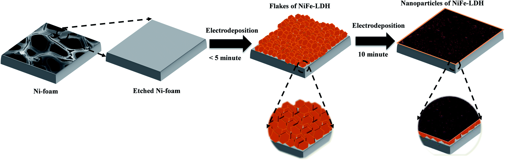 | ||
| Scheme 1 Schematic illustration of electrodeposition of NiFe-based electrocatalysts on NF. | ||
Bimetallic hydroxide was then deposited on the electrode surface by the reaction of Ni2+ and Fe3+ ions with locally generated hydroxide ions.47 This electrodeposition process resulted in the growth of brown-colored hydroxide on the NF substrate (Fig. S1†).
Deposition time played a crucial role in the growth of hydroxide on the NF substrate. Sun et al. reported the initial growth of a honeycomb-like structure on the substrate, followed by growth of a spherical particulate structure.48 In the present study, the same growth pattern was observed during the electrodeposition of bare and doped electrocatalysts (Fig. S2†). The morphologies and structures of the obtained deposits were analyzed by FE-SEM and TEM. The FE-SEM and TEM images of NiFe0.8Ce0.2 deposited over 10 min are shown in Fig. 1a–g, along with the EDS color maps (Fig. 1h). For comparison, FE-SEM and TEM images of NiFe, NiFe0.9Ce0.1, and NiFe0.7Ce0.3 samples are provided in Fig. S3, S4, and S5,† respectively. The FE-SEM images revealed that the surface roughness increased after doping of Ce into the NiFe structure. The FE-SEM images of NiFe0.8Ce0.2 at different magnifications revealed clusters of small nanoparticles (Fig. 1a–c). The TEM images in Fig. 1d and e also showed that the NiFe0.8Ce0.2 sample was composed of amorphous nanoparticles. However, from the TEM images, it was very difficult to determine the size of the nanoparticles. The measured lattice fringes with a spacing of 0.25 nm corresponded to the (012) plane of NiFe-LDH, indicating the formation of the LDH phase (Fig. 1f). The inset of Fig. 1f shows the selected area electron diffraction (SAED) pattern with a faint diffused halo, which was attributed to the poor crystallinity of NiFe0.8Ce0.2. The diffraction rings were assigned to the (012) and (113) planes of NiFe-LDH. FE-SEM EDS color mapping of the electrocatalysts indicated uniform distribution of Ni, Fe, Ce, and O in the structures (Fig. 1g, h and S6†). Table S1† summarizes the atomic percentages of Ni, Fe, O, and Ce in the synthesized electrocatalysts. Increasing the Ce doping in NiFe-LDH (NiFe1−xCex, x > 0.2) decreased the surface roughness (Fig. S5a and b†).
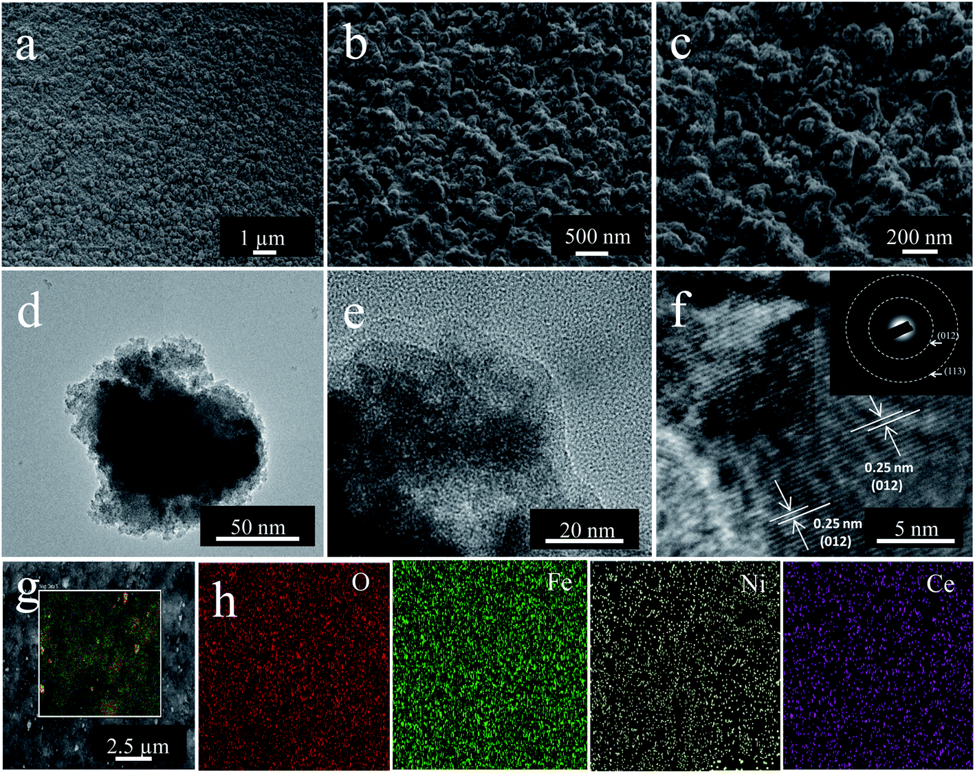 | ||
| Fig. 1 (a–c) FE-SEM images of NiFe0.8Ce0.2. (d and e) TEM and (f) HR-TEM (inset: SAED pattern) images of NiFe0.8Ce0.2 at various levels of magnification. (g) Overlapped FE-SEM image and (h) FE-SEM EDS elemental color maps of NiFe0.8Ce0.2. | ||
Phase determination for the NiFe-based samples was carried out by XRD analysis. The XRD patterns of the samples are shown in Fig. 2. The patterns of the samples deposited on NF contained only peaks associated with NF (Fig. 2a). The powders scratched off the NF substrate were thus analyzed (Fig. 2b). In all of the XRD patterns, three peaks located at 44.7°, 52.06°, and 76.52° were indexed to the fcc structure of nickel (JCPDS no. 04-0850). The NiFe patterns contained three distinct diffraction peaks at 11.3°, 34.4°, and 59.95°, which were indexed to the (003), (012), and (110) planes of NiFe-LDH (JCPDS no. 040-0215). The low intensity and broad nature of these diffraction peaks indicated smaller particles with poor crystallinity. Additionally, it is observed that with the Ce doping in the NiFe-LDH structure, the intensity of diffraction peaks decreased drastically, which was attributed to the more amorphous structure. However, two additional peaks were observed in the pattern of the NiFe0.7Ce0.3 sample at 28.25° and 47.5°, which were readily indexed to the (101) and (002) planes, respectively, of Ce(OH)3 (JCPDS no. 019-0284). The XRD results indicated that in NiFe1−xCex, (x = 0.1 and 0.2), Ce doping did not change the layered structure. However, an additional Ce(OH)3 phase was formed with increased Ce doping.
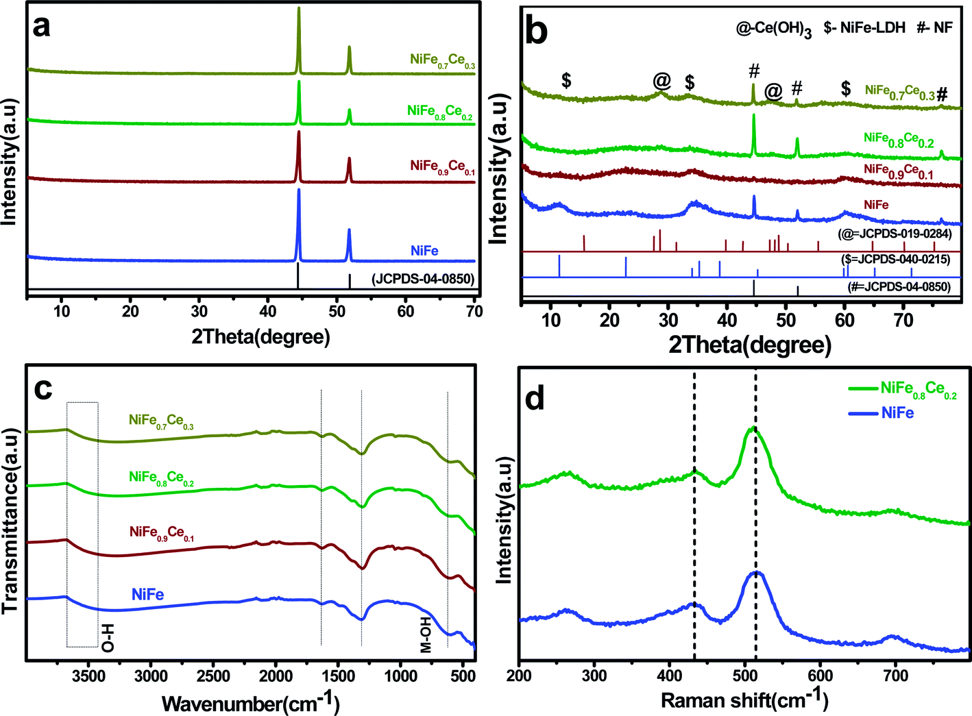 | ||
| Fig. 2 (a) XRD patterns of electrodeposited electrocatalysts on NF, (b) XRD patterns of electrocatalyst powders, (c) LDH FT-IR spectra, and (d) Raman spectra of powders scratched from the NF substrate. | ||
FT-IR analysis was used to determine the molecular vibrations of the intercalated anions in the LDH. The broad and intense absorption bands between 3670 and 3400 cm−1 (Fig. 2c) were assigned to the stretching vibration of the O–H bond in interlayer water molecules.49 The band centered around 1630 cm−1 was attributed to the bending vibration of the water molecule, which confirmed the presence of molecular water in the material structure.50 The band at 1310 cm−1 was ascribed to the vibration of interlayer NO3− anions. The band centered at around 608 cm−1 was attributed to the vibrations of metal–O and O–metal–O bonds. The slight shift in the absorption bands of the NiFe0.9Ce0.1, NiFe0.8Ce0.2, and NiFe0.7Ce0.3 samples suggested that new metal–O and O–metal–O bonds were formed in NiFe-LDH after Ce doping. Broadening of absorption peaks after Ce doping was attributed mainly to the formation of lattice defects in the material structure.45,51Fig. 2d shows the Raman spectra of the undoped (NiFe) and Ce-doped (NiFe0.8Ce0.2) samples. The Raman spectra displayed two characteristics peaks at around 434 cm−1 and 515 cm−1, which were attributed to the E2g and A1g vibrational modes of phonons. The absence of additional peaks after doping indicated the formation of pure-phase NiFe-LDH.
XPS analysis was carried out to determine the chemical states of the as-deposited NiFe and NiFe0.8Ce0.2 electrocatalysts (Fig. 3). The deconvoluted Ni 2p, Fe 2p, and O 1s spectra are shown in Fig. 3a–c. In the Ni 2p region in the spectra of the NiFe electrocatalysts, the two peaks located at binding energies (BE) of 855.5 eV and 873.30 eV were assigned to Ni2+.52 Two peaks located at BE 712.2 eV and 726.7 eV in the Fe 2p region were assigned to Fe3+.53 Three peaks in the O 1s region located at 529.5, 531.2, and 532.2 eV were attributed to the oxygen in M–O, M–OH, and adsorbed H2O, respectively.53,54 Substitution of Ce in the Fe sites of NiFe resulted in a positive shift of the Ni 2p, Fe 2p, and O 1s peaks to higher BEs, as shown in Fig. 3a–c. The positive shift of ∼0.7 eV in the BEs of Ni 2p and Fe 2p indicated strong electronic interactions and modification of the electronic structure in NiFe-LDH due to partial Ce substitution. The positive shift in BE also indicated that Ce could promote the formation of Ni3+ cations to some extent, and that these formed NiOOH that could act as active centers for the OER.55 The high-resolution XPS spectra of Ce 3d exhibited two peaks at 920–910 eV and 909–897 eV, which could be assigned to Ce 3d3/2, and the peaks at 892–877 eV are attributable to Ce 3d5/2. These results indicated the coexistence of Ce3+ and Ce4+ in the NiFe0.8Ce0.2 structure.45
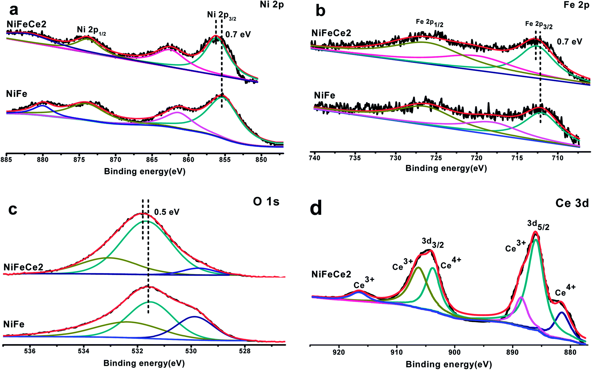 | ||
| Fig. 3 High-resolution XPS spectra of (a) Ni 2p, (b) Fe 2p, (c) O 1s, and (d) Ce 3d in the NiFe and NiFe0.8Ce0.2 electrocatalysts. | ||
3.2 Electrochemical activity
It is well reported that Ce doping in the NiFe-LDH structure can change its crystal/electronic structure. First, the need for a high and flexible coordination number of cerium results in the formation of an 8-fold dodecahedron polyhedron or 9-fold monocapped square antiprism coordination layer.56 Therefore, after the incorporation of Ce3+ into the NiFe-LDH structure, the layer composition and the coordination structure of LDH may be changed to contain eight- and nine-coordinate Ce sites with bridging hydroxide groups and coordinated water molecules, which alters the topology of the layer. Also, doping with Ce3+ ions with larger ionic radii can bring about lattice distortion and induce imperfection in the layers. In addition, the flexible transition between the CeIII and CeIV oxidation states could increase the oxygen-storage capacity of Ce ions, which is beneficial to more NiIII/IV species.44 Also, Ce-doping in the LDH structure increases the catalytically active sites which is also confirmed by active site calculation. Therefore, it is believed that abundant active sites and increased oxygen-storage capacity can boost the catalytic activity of Ce doped NiFe electrocatalysts.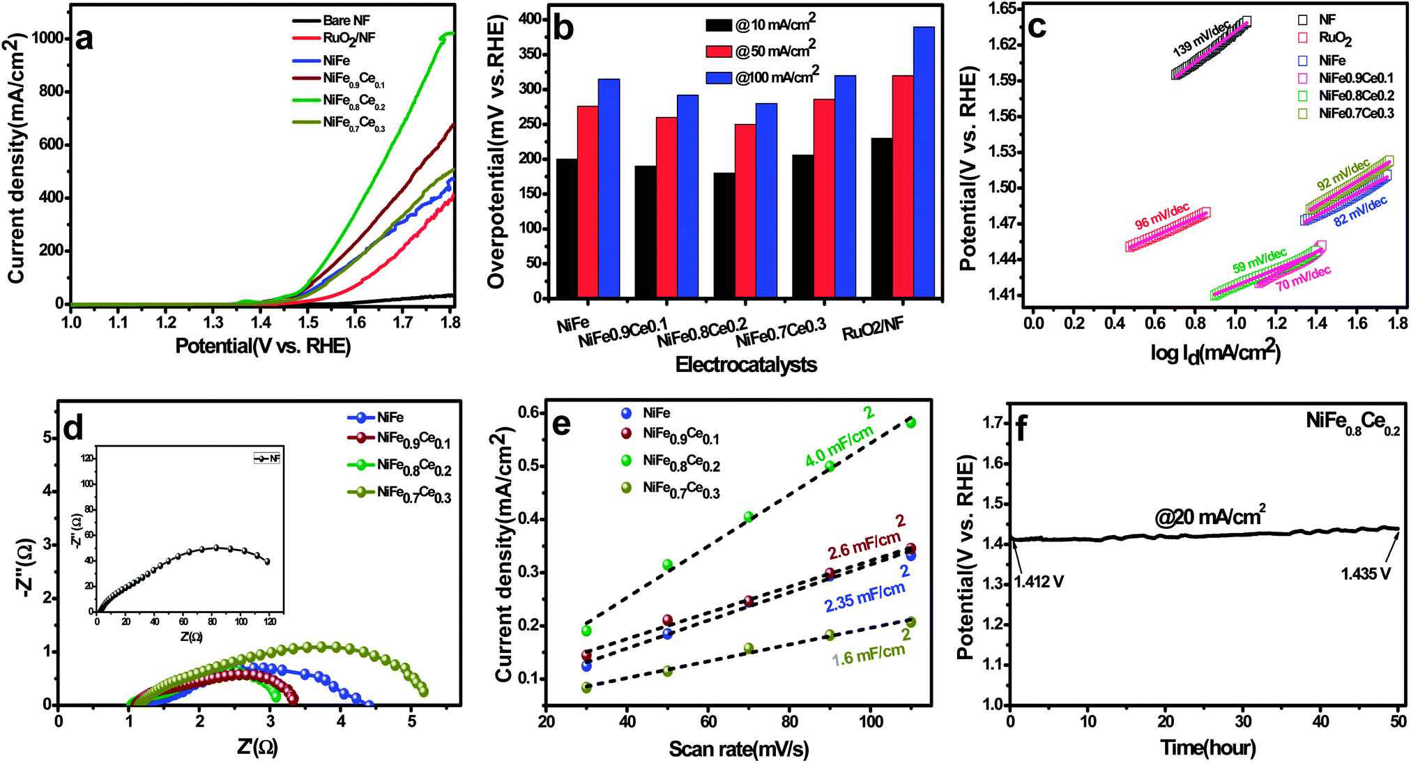 | ||
| Fig. 4 OER performance evaluated in 1 M KOH. (a) Polarization curves, (b) overpotential at a current density of 10 mA cm−2, (c) Tafel plots, (d) Nyquist plots (overpotential = 250 mV), (e) capacitive current as a function of scan rate, and (f) chronopotentiometry curve of the NiFe0.8Ce0.2 electrocatalyst tested at a constant current density of 20 mA cm−2 for 50 h. | ||
The Tafel slopes were obtained by plotting data from the polarization curves to gain insight into the reaction kinetics of the OER (Fig. 4c). The Tafel slopes for NiFe, NiFe0.9Ce0.1, NiFe0.8Ce0.2, NiFe0.7Ce0.3, RuO2, and NF were 82, 70, 59, 92, 126, and 139 mV dec−1, respectively. In general, the Tafel slope can be used to identify the rate-determining step in a four-electron transfer process. The Tafel slope values close to 120, 40 and 28 mV dec−1 are anticipated if the 1st, 2nd, and 3rd electron transfer steps are the rate limiting steps, respectively.64 The NiFe0.8Ce0.2 electrocatalyst yielded the lowest Tafel slope, indicating that it had the most favorable OER kinetics among all of the catalysts investigated in this study. Its superior OER activity was also attributed to its rapid charge transfer properties. Electrochemical impedance spectroscopy (EIS) was performed to determine the charge-transfer resistance of the NiFe-based electrocatalysts (Fig. 4d). The Nyquist plots show semicircles for all of the electrocatalysts and were fitted well with the equivalent circuit composed of series resistance (Rs), charge-transfer resistance (Rct), and a constant phase element CPE (Fig. S8†). The Rs and Rct values obtained after fitting the Nyquist plots are summarized in Table S4.† The NiFe0.8Ce0.2 electrocatalyst had the lowest Rct value, which was consistent with its lower charge transfer resistance and better charge transfer kinetics for the OER. The ECSA, roughness factor, and the number of active sites available for reaction are crucial parameters for determining the catalytic performance of any electrocatalyst. The ECSAs of all of the electrocatalysts were calculated from their double-layer capacitance (DLC) by measuring the CV curves in the non-faradaic region at different scan rates (Fig. S9†). Fig. 4e shows the plots of current density as a function of different scan rates. The slope obtained after fitting is the DLC of the respective electrocatalyst. The ECSAs were directly proportional to the DLC values.
Table S5† summarizes the DLC, ECSA, and roughness factors of the electrocatalysts. Among the electrocatalysts, NiFe0.8Ce0.2 exhibited the highest DLC and ECSA values of 4.0 mF cm−2 and 100 cm2, respectively. The increased surface area of the NiFe electrocatalysts after Ce doping was attributed to variations in their physical structures, which was confirmed by the results of the XRD and XPS analyses. In addition, the large ECSA of NiFe0.8Ce0.2 suggested that it had a higher roughness factor. This is because the active surface area is positively associated with the roughness factor.65 A large ECSA can provide plentiful active sites for catalytic reactions. The number of active sites in the electrocatalysts was evaluated by CV in phosphate buffer solution at pH 7 (Fig. S10†). The calculated number of active sites in the NiFe, NiFe0.9Ce0.1, NiFe0.8Ce0.2, and NiFe0.7Ce0.3 electrocatalysts was 7.66 × 10⁻⁵, 10.13 × 10⁻⁵, 14.04 × 10⁻⁵, and 4.43 × 10⁻⁵ mol, respectively. Therefore, the larger ECSA with abundant active sites and the roughness factor of NiFe0.8Ce0.2 were responsible for its superior catalytic activity towards the OER. We additionally normalized the current density of the OER with respect to the calculated ECSA. As shown in Fig. S11,† NiFe0.8Ce0.2 exhibited the best OER catalytic activity among all electrocatalysts.
Long-term durability is another decisive measure to evaluate the catalyst performance during the OER. Determination of the stability of the NiFe0.8Ce0.2 electrocatalyst was carried out at a fixed current density of 20 mA cm−2 for 50 h at room temperature. Fig. 4f shows the initial potential of 1.412 V, which increased to 1.435 V after 50 h of stability testing for the OER reaction. The negligible increase in potential after 50 hour stability testing demonstrated the excellent stability of the NiFe0.8Ce0.2 electrocatalyst. In addition, the LSV measurements following the stability test did not indicate any significant change in activity with a slight decrease in the current density (Fig. S12†).
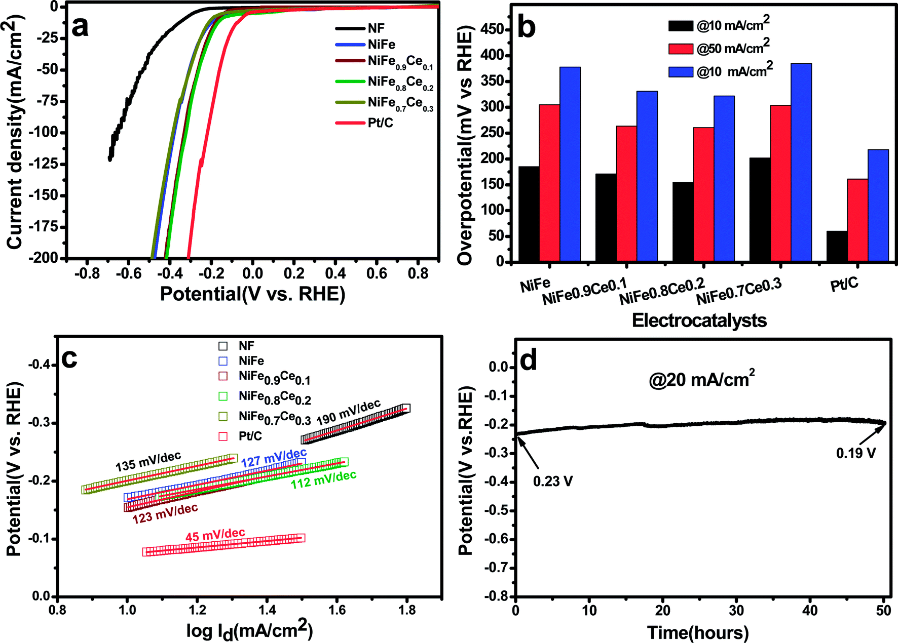 | ||
| Fig. 5 HER performance evaluated in 1 M KOH. (a) Polarization curves, (b) overpotential at a current density of 10 mA cm−2, (c) Tafel plots, and (d) chronopotentiometry curve of the NiFe0.8Ce0.2 electrocatalyst over 50 h at a constant current density of 20 mA cm−2. | ||
The long-term stability of NiFe0.8Ce0.2 for the HER was evaluated with chronopotentiometric measurements over 50 h in 1 M KOH at a current density of 20 mA cm−2. The stability test showed an initial potential of 230 mV, which decreased to 190 mV after 50 h. The decrease in overpotential with time could be attributed to activation of the electrocatalyst. In addition, the polarization curve obtained after 50 h of stability testing was almost identical to the curve recorded prior to testing (Fig. S14†).
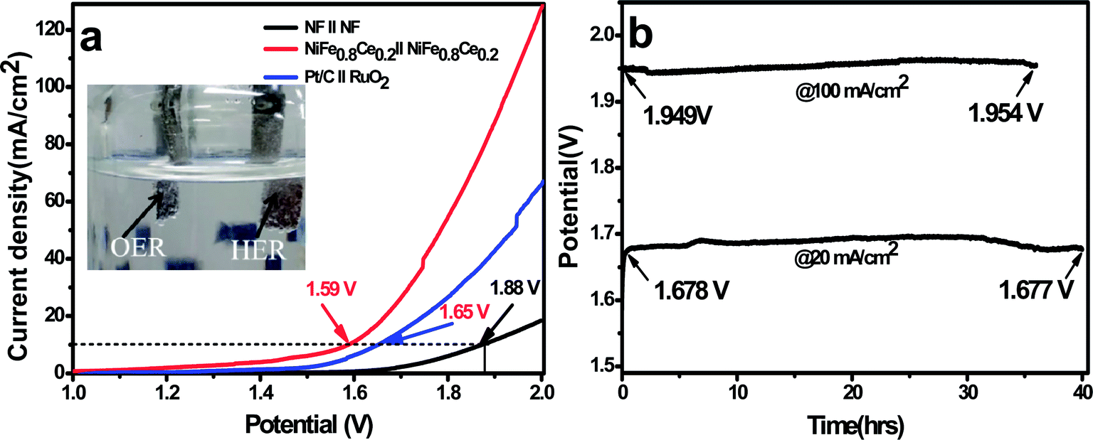 | ||
| Fig. 6 Overall water-splitting performance. (a) Polarization curves for overall water-splitting with NiFe0.8Ce0.2/NF serving as both the cathode and anode at a scan rate of 2 mV s−1. (b) Chronopotentiometry curves of the NiFe0.8Ce0.2 electrocatalyst at a current density of 20 and 100 mA cm−2 collected using a two-electrode configuration in 1 M KOH electrolyte. | ||
FE-SEM analysis was carried out after the long-term stability test to examine the surface morphology changes in the electrocatalyst. FE-SEM images of both the anode and cathode showed smoother surfaces without obvious changes from their original morphology (Fig. S15 and S16†). In addition, elemental color mapping indicated the presence of Ni, Fe, Ce, O, and K in the tested electrodes. The source of K was KOH used as the alkaline electrolyte during electrochemical analysis. The XPS analysis after the long-term OER stability test is summarized in Fig. S17.† The shift in Ni 2p spectra after the OER test reveals the formation of NiOOH.77 However, no major shift was observed for Fe, Ce, and O elements. Our results collectively confirm the high efficiency and stability of the NiFe0.8Ce0.2 electrocatalyst for overall water splitting.
This superior catalytic performance of NiFe0.8Ce0.2 establishes its great potential as a bifunctional electrocatalyst for the overall water-splitting reaction. Its performance can be ascribed to its enhanced affinity for the reaction intermediates, OH− and H+, as well as its excellent charge-transfer kinetics. Its porous structure increases the specific surface area to create a large reaction interface, which facilitates electrolyte diffusion and assists with the release of evolved gas bubbles. Additionally, its large ECSA provides a large number of surface active sites, which eases the diffusion of active species and accelerates the catalytic reaction. With its microporous structure, the use of 3D NF as the electrocatalyst substrate confers the advantages of high electrical conductivity, good mechanical adhesion, and accelerated ion and electrolyte diffusion. These features are favorable for the enhancement of OER and HER activity.
4. Conclusions
In this work, we demonstrated the rapid synthesis of Ce-doped NiFe-LDH electrocatalysts at room temperature for water splitting applications. The NiFe0.8Ce0.2 electrocatalyst exhibited superior bifunctional OER and HER catalytic activity and long-term stability in alkaline solution. To achieve a current density of 10 mA cm−2 for the OER and HER, this catalyst required an overpotential of 175 and 147 mV, respectively. Ce doping in the NiFe-LDH structure results in high electrocatalytic activity, mainly attributed to its large surface area, abundance of active sites, and its higher degree of surface roughness. Furthermore, a two-electrode electrolyzer (NiFe0.8Ce0.2‖NiFe0.8Ce0.2) for overall water splitting in alkaline solution required a cell voltage of 1.59 V to achieve a current density of 10 mA cm−2, and it remained highly stable for 40 hours at an applied constant current density of 20 mA cm−2. The present synthesis approach presented here paired with selection of an appropriate dopant can pave the way for exploring facile, low-cost, and scalable synthesis of novel, highly active electrocatalysts and electrodes for energy storage and conversion applications.Conflicts of interest
There are no conflicts to declare.Acknowledgements
This work was supported by the National Research Foundation of Korea (NRF) funded by the Ministry of Education (NRF 2016R1D1A1B03930855 and No. 2009-0093816). This work was also supported by Nano-Material Fundamental Technology Development (2016M3A7B4909370) through the National Research Foundation of Korea (NRF) funded by the Ministry of Science, ICT, and Future Planning.References
- T. F. J. Zhi Wei Seh, J. Kibsgaard, C. F. Dickens, I. Cholkendroff and J. K. Norskov, Science, 2017, 355, 4998–5009 CrossRef PubMed.
- S. Chu and A. Majumdar, Nature, 2012, 488, 294–303 CrossRef CAS PubMed.
- Y. Jiao, Y. Zheng, M. Jaroniec and S. Z. Qiao, Chem. Soc. Rev., 2015, 44, 2060–2086 RSC.
- F. Yu, L. Yu, I. K. Mishra, Y. Yu, Z. F. Ren and H. Q. Zhou, Materials Today Physics, 2018, 7, 121–138 CrossRef.
- Y. Wang, D. Yan, S. El Hankari, Y. Zou and S. Wang, Adv. Sci., 2018, 5, 1800064 CrossRef PubMed.
- P. Zhang, J. Zhang and J. Gong, Chem. Soc. Rev., 2014, 43, 4395–4422 RSC.
- B. Zhang, X. Zheng, O. Voznyy, R. Comin, M. Bajdich, M. García-Melchor, L. Han, J. Xu, M. Liu, L. Zheng, F. P. G. de Arquer, C. T. Dinh, F. Fan, M. Yuan, E. Yassitepe, N. Chen, T. Regier, P. Liu, Y. Li, P. De Luna, A. Janmohamed, H. L. Xin, H. Yang, A. Vojvodic and E. H. Sargent, Science, 2016, 352, 333–337 CrossRef CAS PubMed.
- E. Detsi, J. B. Cook, B. K. Lesel, C. L. Turner, Y.-L. Liang, S. Robbennolt and S. H. Tolbert, Energy Environ. Sci., 2016, 9, 540–549 RSC.
- F. Cheng, J. Shen, B. Peng, Y. Pan, Z. Tao and J. Chen, Nat. Chem., 2011, 3, 79–84 CrossRef CAS PubMed.
- K. Fominykh, P. Chernev, I. Zaharieva, J. Sicklinger, G. Stefanic, M. Döblinger, A. Müller, A. Pokharel, S. Böcklein, C. Scheu, T. Bein and D. Fattakhova-Rohlfing, ACS Nano, 2015, 9, 5180–5188 CrossRef CAS PubMed.
- Y. Hou, M. R. Lohe, J. Zhang, S. Liu, X. Zhuang and X. Feng, Energy Environ. Sci., 2016, 9, 478–483 RSC.
- D. Liang, S. Wu, J. Liu, Z. Tian and C. Liang, J. Mater. Chem. A, 2016, 4, 10609–10617 RSC.
- T. Liu, A. M. Asiri and X. Sun, Nanoscale, 2016, 8, 3911 RSC.
- K. Xiong, L. Li, L. Zhang, W. Ding, L. Peng, Y. Wang, S. Chen, S. Tan and Z. Wei, J. Mater. Chem. A, 2015, 3, 1863–1867 RSC.
- C. Panda, P. W. Menezes, C. Walter, S. Yao, M. E. Miehlich, V. Gutkin, K. Meyer and M. Driess, Angew. Chem., Int. Ed., 2017, 56, 10506–10510 CrossRef CAS PubMed.
- F. Lyu, Y. Bai, Z. Li, W. Xu, Q. Wang, J. Mao, L. Wang, X. Zhang and Y. Yin, Adv. Funct. Mater., 2017, 27, 1702324 CrossRef.
- Q. Kang, L. Vernisse, R. C. Remsing, A. C. Thenuwara, S. L. Shumlas, I. G. McKendry, M. L. Klein, E. Borguet, M. J. Zdilla and D. R. Strongin, J. Am. Chem. Soc., 2017, 139, 1863–1870 CrossRef CAS PubMed.
- Y. Jin, H. Wang, J. Li, X. Yue, Y. Han, P. Kang Shen, Y. Cui, Y. Jin, Y. Han, P. K. Shen, J. Li, X. Yue, H. Wang and Y. Cui, Adv. Mater., 2016, 28, 3785–3790 CrossRef CAS PubMed.
- Y. P. Zhu, T. Y. Ma, M. Jaroniec and S. Z. Qiao, Angew. Chem., Int. Ed., 2017, 56, 1324–1328 CrossRef CAS PubMed.
- L. Huang, J. Jiang and L. Ai, ACS Appl. Mater. Interfaces, 2017, 9, 7059–7067 CrossRef CAS PubMed.
- G. Liu, P. Li, G. Zhao, X. Wang, J. Kong, H. Liu, H. Zhang, K. Chang, X. Meng, T. Kako and J. Ye, J. Am. Chem. Soc., 2016, 138, 9128–9136 CrossRef CAS PubMed.
- T. Yoon and K. S. Kim, Adv. Funct. Mater., 2016, 26, 7386–7393 CrossRef CAS.
- H. Li, C. Tsai, A. L. Koh, L. Cai, A. W. Contryman, A. H. Fragapane, J. Zhao, H. S. Han, H. C. Manoharan, F. Abild-Pedersen, J. K. Nørskov and X. Zheng, Nat. Mater., 2016, 15, 48–53 CrossRef CAS PubMed.
- S. Zhao, R. Jin, H. Abroshan, C. Zeng, H. Zhang, S. D. House, E. Gottlieb, H. J. Kim, J. C. Yang and R. Jin, J. Am. Chem. Soc., 2017, 139, 27 CrossRef PubMed.
- H. Li, S. Chen, H. Lin, X. Xu, H. Yang, L. Song and X. Wang, Small, 2017, 13, 1701487 CrossRef PubMed.
- Z.-H. Xue, H. Su, Q.-Y. Yu, B. Zhang, H.-H. Wang, X.-H. Li and J.-S. Chen, Adv. Energy Mater., 2017, 7, 1602355 CrossRef.
- J. Xu, X.-K. Wei, J. Josédiogo Costa, J. J. Lado, B. Owens-Baird, L. P. L. Gonç Alves, S. P. S. Fernandes, M. Heggen, D. Y. Petrovykh, R. E. Dunin-Borkowski, K. Kovnir and Y. V. Kolen'ko, ACS Catal., 2017, 7, 5450–5455 CrossRef CAS.
- I. K. Mishra, H. Zhou, J. Sun, K. Dahal, Z. Ren, R. He, S. Chen and Z. Ren, Materials Today Physics, 2018, 4, 1–6 CrossRef.
- Y. Fan, S. Ida, A. Staykov, T. Akbay, H. Hagiwara, J. Matsuda, K. Kaneko, T. Ishihara, B. Y. Electrocatalysts Fan, S. Ida, A. Staykov, T. Akbay, H. Hagiwara, T. Ishihara, Y. Fan, J. Matsuda and K. Kaneko, Small, 2017, 13, 1700099 CrossRef PubMed.
- G. Fu, Z. Cui, Y. Chen, L. Xu, Y. Tang and J. B. Goodenough, Nano Energy, 2017, 39, 77–85 CrossRef CAS.
- T. Y. Ma, J. L. Cao, M. Jaroniec and S. Z. Qiao, Angew. Chem., Int. Ed., 2016, 55, 1138–1142 CrossRef CAS PubMed.
- J.-T. Ren, G.-G. Yuan, C.-C. Weng, L. Chen and Z.-Y. Yuan, Nanoscale, 2018, 10, 10620–10628 RSC.
- F. Song and X. Hu, Nat. Commun., 2014, 5, 4477 CrossRef CAS PubMed.
- Y. Wang, F. Li, S. Dong, X. Liu and M. Li, J. Colloid Interface Sci., 2016, 467, 28–34 CrossRef CAS PubMed.
- H. Liang, F. Meng, M. Cabáncabán-Acevedo, L. Li, A. Forticaux, L. Xiu, Z. Wang and S. Jin, Nano Lett., 2015, 14, 14 Search PubMed.
- F. Song and X. Hu, J. Am. Chem. Soc., 2014, 136, 16 CrossRef PubMed.
- J. Ping, Y. Wang, Q. Lu, B. Chen, J. Chen, Y. Huang, Q. Ma, C. Tan, J. Yang, X. Cao, Z. Wang, J. Wu, Y. Ying and H. Zhang, Adv. Mater., 2016, 28, 7640–7645 CrossRef CAS PubMed.
- A. Sumboja, J. Chen, Y. Zong, P. S. Lee and Z. Liu, Nanoscale, 2016, 9, 774 RSC.
- Y. Lv, A. Batool, Y. Wei, Q. Xin, R. Boddula, S. U. Jan, M. Z. Akram, L. Tian, B. Guo and J. R. Gong, ChemElectroChem, 2019, 6, 2497–2502 CrossRef CAS.
- X. Li, X. Hao, Z. Wang, A. Abudula and G. Guan, J. Power Sources, 2017, 347, 193–200 CrossRef CAS.
- B. Guo, A. Batool, G. Xie, R. Boddula, L. Tian, S. U. Jan and J. R. Gong, Nano Lett., 2018, 18, 1516–1521 CrossRef CAS PubMed.
- A. Alarawi, V. Ramalingam and J. H. He, Mater. Today Energy, 2019, 11, 1–23 CrossRef.
- D. Xu, M. B. Stevens, Y. Rui, G. DeLuca, S. W. Boettcher, E. Reichmanis, Y. Li, Q. Zhang and H. Wang, Electrochim. Acta, 2018, 265, 10–18 CrossRef CAS.
- Q. Zhang, S. Zhang, Y. Tian and S. Zhan, ACS Sustainable Chem. Eng., 2018, 6, 15411–15418 CrossRef CAS.
- H. Xu, B. Wang, C. Shan, P. Xi, W. Liu and Y. Tang, ACS Appl. Mater. Interfaces, 2018, 10, 6336–6345 CrossRef CAS PubMed.
- P. Babar, A. Lokhande, H. H. Shin, B. Pawar, M. G. Gang, S. Pawar and J. H. Kim, Small, 2018, 14, 1702568 CrossRef PubMed.
- X. Lu and C. Zhao, Nat. Commun., 2015, 6, 6616 CrossRef CAS PubMed.
- Y. Sun, C. Liu, L. Zhang, P. Wan, S. Zhuang, Y. Tang, Y. Chen and J. Pan, ChemElectroChem, 2017, 4, 1044–1050 CrossRef CAS.
- X. Cheng, X. Huang, X. Wang and D. Sun, J. Hazard. Mater., 2010, 177, 516–523 CrossRef CAS PubMed.
- R. K. Sahu, B. S. Mohanta and N. N. Das, J. Phys. Chem. Solids, 2013, 74, 1263–1270 CrossRef CAS.
- Z. Li, M. Shao, H. An, Z. Wang, S. Xu, M. Wei, D. G. Evans and X. Duan, Chem. Sci., 2015, 6, 6624–6631 RSC.
- F. Wang, T. Wang, S. Sun, Y. Xu, R. Yu and H. Li, Sci. Rep., 2018, 8, 8908 CrossRef PubMed.
- X. Bo, Y. Li, R. K. Hocking and C. Zhao, ACS Appl. Mater. Interfaces, 2017, 9, 41239–41245 CrossRef CAS PubMed.
- H. S. Jadhav, A. C. Lim, A. Roy and J. G. Seo, ChemistrySelect, 2019, 4, 2409–2415 CrossRef CAS.
- W. Zhu, L. Liu, Z. Yue, W. Zhang, X. Yue, J. Wang, S. Yu, L. Wang and J. Wang, ACS Appl. Mater. Interfaces, 2017, 9, 19807–19814 CrossRef CAS PubMed.
- J. Wu, J. Liang, R. Ma and T. Sasaki, J. Phys. Chem. C, 2015, 119, 26229–26236 CrossRef CAS.
- H. Zhang, X. Li, A. Hähnel, V. Naumann, C. Lin, S. Azimi, S. L. Schweizer, A. W. Maijenburg and R. B. Wehrspohn, Adv. Funct. Mater., 2018, 28, 1706847 CrossRef.
- Z. Lu, W. Xu, W. Zhu, Q. Yang, X. Lei, J. Liu, Y. Li, X. Sun and X. Duan, Chem. Commun., 2014, 50, 6479–6482 RSC.
- X. Long, J. Li, S. Xiao, K. Yan, Z. Wang, H. Chen and S. Yang, Angew. Chem., Int. Ed., 2014, 53, 7584–7588 CrossRef CAS PubMed.
- W. Ma, R. Ma, C. Wang, J. Liang, X. Liu, K. Zhou and T. Sasaki, ACS Nano, 2015, 9, 1977–1984 CrossRef CAS PubMed.
- L. Yu, H. Zhou, J. Sun, F. Qin, F. Yu, J. Bao, Y. Yu, S. Chen and Z. Ren, Energy Environ. Sci., 2017, 10, 1820 RSC.
- Y. Jia, L. Zhang, G. Gao, H. Chen, B. Wang, J. Zhou, M. T. Soo, M. Hong, X. Yan, G. Qian, J. Zou, A. Du and X. Yao, Adv. Mater., 2017, 29, 1700017 CrossRef PubMed.
- H. Liang, A. N. Gandi, C. Xia, M. N. Hedhili, D. H. Anjum, U. Schwingenschlö and H. N. Alshareef, ACS Energy Lett., 2017, 2, 1035–1042 CrossRef CAS.
- H. A. Bandal, A. R. Jadhav, A. H. Tamboli and H. Kim, Electrochim. Acta, 2017, 249, 253–262 CrossRef CAS.
- H. S. Jadhav, A. Roy, G. M. Thorat, W.-J. Chung and J. G. Seo, J. Ind. Eng. Chem., 2019, 71, 452–459 CrossRef CAS.
- C. Xiao, Y. Li, X. Lu and C. Zhao, Adv. Funct. Mater., 2016, 26, 3515–3523 CrossRef CAS.
- L.-L. Feng, G. Yu, Y. Wu, G.-D. Li, H. Li, Y. Sun, T. Asefa, W. Chen and X. Zou, J. Am. Chem. Soc., 2015, 137, 14023–14026 CrossRef CAS PubMed.
- L. Yu, H. Zhou, J. Sun, F. Qin, D. Luo, L. Xie, F. Yu, J. Bao, Y. Li, Y. Yu, S. Chen and Z. Ren, Nano Energy, 2017, 41, 327–336 CrossRef CAS.
- Z. Wang, S. Zeng, W. Liu, X. Wang, Q. Li, Z. Zhao and F. Geng, ACS Appl. Mater. Interfaces, 2017, 9, 1488–1495 CrossRef CAS PubMed.
- K. N. Dinh, P. Zheng, Z. Dai, Y. Zhang, R. Dangol, Y. Zheng, B. Li, Y. Zong and Q. Yan, Small, 2018, 14, 1703257 CrossRef PubMed.
- C. Tang, N. Cheng, Z. Pu, W. Xing and X. Sun, Angew. Chem., Int. Ed., 2015, 54, 9351–9355 CrossRef CAS PubMed.
- J. Luo, J.-H. Im, M. T. Mayer, M. Schreier, M. K. Nazeeruddin, N.-G. Park, S. D. Tilley, H. J. Fan and M. Gratzel, Science, 2014, 345, 1593–1596 CrossRef CAS PubMed.
- J. Tian, N. Cheng, Q. Liu, X. Sun, Y. He and A. M. Asiri, J. Mater. Chem. A, 2015, 3, 20056–20059 RSC.
- J. Shi, J. Hu, Y. Luo, X. Sun and A. M. Asiri, Catal. Sci. Technol., 2015, 5, 4954–4958 RSC.
- C. Tang, R. Zhang, W. Lu, L. He, X. Jiang, A. M. Asiri and X. Sun, Adv. Mater., 2017, 29, 1602441 CrossRef PubMed.
- H. Liang, A. N. Gandi, D. H. Anjum, X. Wang and H. N. Alshareef, Nano Lett., 2016, 16, 7718–7725 CrossRef CAS PubMed.
- N. Cheng, Q. Liu, A. M. Asiri, W. Xing and X. Sun, J. Mater. Chem. A, 2015, 3, 23207–23212 RSC.
Footnote |
| † Electronic supplementary information (ESI) available: Optical photographs of bare NF and electrocatalysts deposited on NF; FE-SEM EDS elemental color maps; TEM images of NiFe, NiFe0.9Ce0.1, and NiFe0.7Ce0.3 electrocatalysts; polarization curves obtained after the OER and HER stability tests and CV curves in the non-faradaic region; tables summarizing published findings from a literature survey of various electrocatalysts for the OER, HER, and overall water-splitting reaction in comparison with the electrocatalyst investigated in the present study; CV curves obtained in phosphate buffer solution; FE-SEM and TEM analysis of the anode and cathode after the stability test; video of two-electrode full water splitting. See DOI: 10.1039/c9se00700h |
| This journal is © The Royal Society of Chemistry 2020 |