
Use of a water-in-salt electrolyte to avoid organic material dissolution and enhance the kinetics of aqueous potassium ion batteries†
Hong
Chen
a,
Zhongyu
Zhang
b,
Zhixuan
Wei
b,
Gang
Chen
b,
Xu
Yang
 *c,
Chunzhong
Wang
*b and
Fei
Du
b
*c,
Chunzhong
Wang
*b and
Fei
Du
b
aCollege of Science, Beihua University, Jilin, 132000, PR China
bKey Laboratory of Physics and Technology for Advanced Batteries (Ministry of Education), College of Physics, Jilin University, Changchun, 130012, PR China. E-mail: wcz@jlu.edu.cn
cCollege of Science, Shenyang Aerospace University, Shenyang, 110135, PR China. E-mail: xuyangmark@foxmail.com
First published on 15th October 2019
Abstract
A concentrated water-in-salt electrolyte (WiSE) effectively binds free water molecules, suppressing hydrogen evolution and the dissolution of potassiated perylene-3,4,9,10-tetracarboxylic dianhydride, resulting in improved cycling stability. In addition, easier breakup of the K+ solvation sheath in this WiSE also leads to improved kinetics for faster K+ storage.
With the rapid development of renewable energy sources and technologies, large-scale energy storage systems (EESs) are in extremely urgent demand. High safety, environmental friendliness and long lifespans are important technical parameters for EESs.1–6 Despite the many types of rechargeable batteries that have been investigated, few of them can meet these requirements simultaneously. Metal hydride/nickel cells suffer from low energy density, lead–acid batteries cause serious environmental pollution, and lithium-ion batteries use a flammable electrolyte and hence pose safety issues. Thus, the development of safe electrical storage batteries for large-scale applications has become a priority.7
Aqueous electrolyte rechargeable batteries based on alkali ion intercalation are attractive candidates because of their inherent safety. Aqueous lithium-ion batteries have been comprehensively studied, but the low natural abundance of lithium limits their large-scale application. Potassium (K) is a naturally abundant element and so the use of aqueous K-ion batteries (AKIBs) is a potentially viable technology.8,9 Moreover, AKIBs might achieve a better rate performance than aqueous lithium-ion batteries on account of K+ exhibiting higher mobility than Li+, benefiting from the weaker Lewis acidity of K+ leading to the smaller Stokes radii of solvated ions in liquid electrolyte.10 But the electrochemical stability window of traditional aqueous electrolytes (1.23 V) is too narrow, which imposes an unwanted restriction on the choice of electrochemical couples (cathode and anode materials) and consequently the practical energy output of such aqueous battery chemistries.2,11,12 A “water-in-salt” electrolyte (WiSE) can efficiently bind “free” water because there is more salt than solvent in this binary system, which also benefits both cathodic and anodic stability limits.13–16 Simultaneously, the WiSE electrolyte effectively reduces the solubility of organic materials because of the lack of free water. So far, only a few types of WiSEs have been explored as potential electrolytes for AKIBs. Ji et al. reported a nonfluorinated WiSE, 30 m potassium acetate, with an potential operating window for AKIBs of 3.2 V, and employed KTi2(PO4)3 as the anode material for AKIBs.17 Hu et al. reported a full AKIB fabricated with an Fe-substituted Mn-rich Prussian blue analogue, K1.85Fe0.33Mn0.67[Fe(CN)6]0.98·0.77H2O, as the cathode material, organic 3,4,9,10-perylenetetracarboxylic diimide (PTCDI) as the anode material, and 22 m KCF3SO3 WiSE as the electrolyte.8 So far, the few choices of electrolytes and corresponding materials have limited the development of AKIBs.
Herein, we report on a potassium bis(fluorosulfonyl)imide (KFSI)-based WiSE that expands the electrochemical stability window, thus enabling β-perylene-3,4,9,10-tetracarboxylic dianhydride (β-PTCDA) to operate without hydrogen evolution. Our research provides clear evidence that this WiSE can also effectively solve the problem of material dissolution, thereby significantly increasing the cycling stability of β-PTCDA. Also, an assembled aqueous full battery shows great rate performance and long lifespan, suggesting that it is a suitable energy storage device for mid- to large-scale applications.
In traditional aqueous electrolytes (∼1.0 m), the average number of water molecules available to solvate each ion is far higher than the “solvation number”. LiTFSI-H2O (21 m) has been reported to form a liquefied salt, attributed to there being barely enough water molecules available for solvation.13 Due to the higher ionicity of K+ than that of Li+, the concentration of KFSI can reach 30 m, with an accompanying theoretical molar ratio of water to salt of only 1.85 (Fig. S1†). Additionally, the conductivity of the KFSI-based electrolyte was observed to also exceed those of KAc-based and LiTFSI-based electrolytes at the corresponding concentration (Fig. S2†).17 Subsequently, linear sweep voltammetry (LSV) was employed to evaluate the effect of concentration on the electrochemical stability window of the KFSI-H2O electrolyte. As shown in Fig. 1a, the overall stability window expanded as the concentration of KFSI was increased. When the concentration of the salt was increased to 30 m, a wide electrochemical stability window of 3.97 V was achieved, with cathodic and anodic limits located at −1.55 and 2.42 V vs. Hg/Hg2Cl2, respectively. With this electrolyte, aqueous batteries may operate well using an electrode made of organic materials, which was previously only viable in non-aqueous batteries.
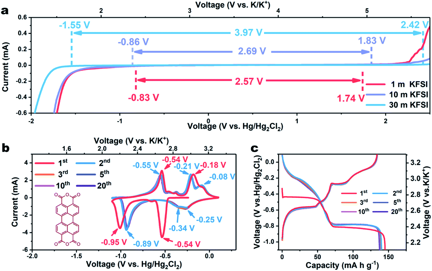 | ||
| Fig. 1 (a) Linear voltammetry curves recorded at 10 mV s−1 in 1, 10, and 30 m KFSI electrolyte, respectively. (b) CV profiles of β-PTCDA measured using a three-electrode battery at a scan rate of 10 mV s−1. (c) Galvanostatic discharge/charge curves at a current density of 0.2 A g−1 in the voltage range of −1.1–0.1 V vs. Hg/Hg2Cl2. | ||
As a proof of concept, we employed a typical organic material, perylene-3,4,9,10-tetracarboxylic dianhydride (β-PTCDA), as an anode material. (For the XRD, FTIR, and SEM results, see Fig. S3–S5†).18 The electrochemical performances of β-PTCDA with an electrolyte of 30 m KFSI were evaluated by assembling them in a three-electrode battery with activated carbon as the counter electrode and Hg/Hg2Cl2 as the reference electrode. Fig. 1b shows the acquired cyclic voltammetry (CV) curves of β-PTCDA between −1.1 and 0.1 V vs. Hg/Hg2Cl2, values obviously beyond the electrochemical stability window of diluted KFSI electrolyte (1 m and 10 m) but within that of concentrated KFSI electrolyte (30 m). Three pairs of redox peaks are observed, which may correspond to the reversible conversion between a C![[double bond, length as m-dash]](https://www.rsc.org/images/entities/char_e001.gif) O bond and a C–O–K bond.19 No extra hydrogen or oxygen evolution peak is detected. After the initial activation process, all CV profiles are almost coincident, indicating the excellent reversibility of β-PTCDA.
O bond and a C–O–K bond.19 No extra hydrogen or oxygen evolution peak is detected. After the initial activation process, all CV profiles are almost coincident, indicating the excellent reversibility of β-PTCDA.
The galvanostatic charge/discharge profiles of β-PTCDA (Fig. 1c) were then evaluated at 0.2 A g−1, which show initial discharge and charge capacities of 145 and 134 mA h g−1, respectively. After the activation process, the anode delivers a stable capacity of 130 mA h g−1, corresponding to a two-electron reaction between β-PTCDA and K2PTCDA.19 The average potential of β-PTCDA is 2.65 V vs. K/K+. Encouraged by the excellent reversibility of β-PTCDA in the 30 m KFSI-based WiSE, we tested the rate capability at various current densities. As shown in Fig. 2a, the electrode shows negligible capacity fading when the current density is increased to 2 A g−1. Even at 8 A g−1, the capacity still retains 83% of its original capacity at 0.2 A g−1.
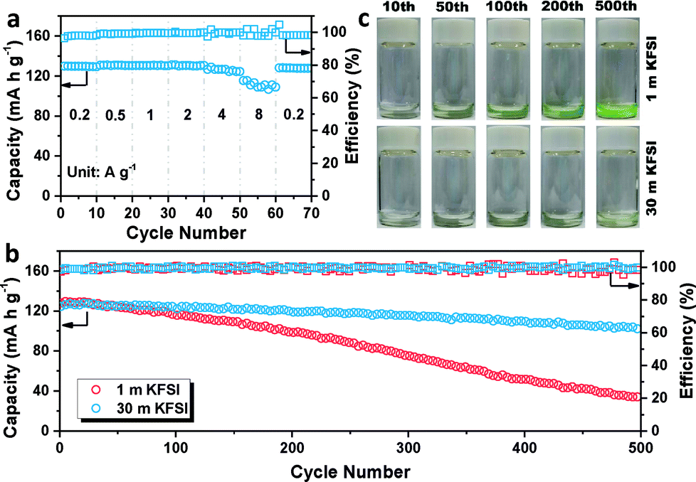 | ||
| Fig. 2 (a) Rate performances of β-PTCDA at current densities from 0.2 to 8 A g−1. (b). Cycle performances of β-PTCDA at a current density of 2 A g−1 for 500 cycles with different electrolytes. (c) Cycled separators soaked in 1 mL of an NaOH solution (2 mol L−1). | ||
Furthermore, the lifespan of β-PTCDA was recorded at 2 A g−1 (Fig. 2b). The battery using a high concentration of KFSI (30 m) presents highly stable cycling stability, delivering a reversible capacity of 101 mA h g−1 after 500 cycles, with a capacity retention of 82%. In contrast, the battery using a low concentration of KFSI (1 m) shows a capacity retention of only 26%. However, this result is not mainly caused by hydrogen evolution. Constant hydrogen evolution has been shown to gradually lead to an increasing amount of OH−, which in turn has been shown to destroy the structure of the anhydride in β-PTCDA and to change the color of β-PTCDA from dark red to green. Interestingly, after disassembling the cell, the color of the dissolved β-PTCDA on the glass fiber separator was still red (Fig. S6†). This unexpected discovery could be explained by there having been insufficient time for hydrogen evolution to have occurred at a high current density of 2 A g−1 (see Fig. S7†). β-PTCDA, as a nonpolar organic material, is barely soluble in water. Nevertheless, after K+ intercalation, the polarity of the material increases and the solubility of K2PTCDA in water correspondingly increases (Fig. S8†). Thus, dissolution of the material is posited to be the main reason for the capacity fading. The cycled separators were then soaked in a color developer consisting of an NaOH solution. A deeper color solution means more dissolved material is left in the separator membrane. As shown in Fig. 2c, the dissolution of active material using 1 m KFSI obviously increases with cycling and that using 30 m KFSI results in a slight change. This result indicates that the WiSE electrolyte can effectively decrease the amount of free water in the electrolyte and solve the problem of material dissolution, thus leading to enhanced cycling stability.
In addition to the dynamic process, a quasi-static process was also investigated using the galvanostatic intermittent titration technique (GITT). Fig. 3a shows the quasi-equilibrium open-circuit-voltage (OCV) and transient-voltage responses of PTCDA in 1 m KFSI electrolyte during the potassiation process. The curve connecting the equilibrium potential points shows a gentle slope below −0.7 V vs. Hg/Hg2Cl2, in contrast to the comparable steep slope resulting from using 30 m KFSI electrolyte. Besides this, the capacity of 209 mA h g−1 is also higher than expected, and due to the hydrogen evolution at low potential, as evidenced in Fig. S9.† This phenomenon indicates that the WiSE can effectively suppress hydrogen evolution. The reaction resistance R was calculated using the equation R = ΔU/i, where ΔU is the overpotential between every discharge potential and the equilibrium potential in the GITT, and i is the pulse current. As shown in Fig. 3c, the cell using 30 m KFSI shows a lower reaction resistance than that using 1 m KFSI, indicating improved kinetics.20,21 Electrochemical impedance spectra (ESI†) were also acquired, as shown in Fig. S10.† The charge-transfer resistance of the battery using 30 m KFSI is observed to be lower than of that using 1 m KFSI. This result can possibly be attributed to improved surface/interface properties, or easier breakup of the K+ solvation sheath in the WiSE, since there are barely enough water molecules available for solvation.
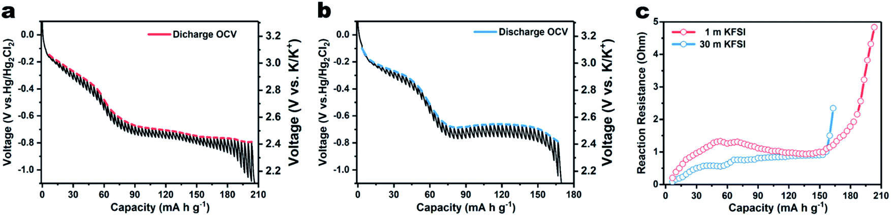 | ||
| Fig. 3 GITT curves of β-PTCDA for K-ion intercalation with (a) 1 m KFSI and (b) 30 m KFSI electrolyte. (c) Reaction resistance of the battery during potassiation. | ||
Finally, a coin-type two-electrode full K-ion battery comprised of a β-PTCDA anode, potassium iron(II) hexacyanoferrate (KFHCF) cathode, and 30 m KFSI electrolyte was assembled. Before constructing the aqueous full K-ion battery (AFKIB), the XRD pattern of KFHCF was acquired (Fig. S11†) and the electrochemical performance (Fig. S12–S14†) of KFHCF in a three-electrode battery with an active carbon counter electrode and Hg/Hg2Cl2 reference electrode was investigated. Fig. 4a shows the galvanostatic charge–discharge profiles of the full battery, which delivers a capacity of 39 mA h g−1 (based on the mass of both the cathode and anode) at 1.25C (1C = 160 mA gcathode−1). The device also shows great rate performance (Fig. 4b), where it still delivers 92% of its original capacity even at 25C. As shown in Fig. S15,† a high energy density of 41 W h kg−1 can be achieved at a power density of 126 W kg−1; the device still delivers an energy density of 37 W h kg−1 at a high-power output of 2467 W kg−1. Thanks to the rapid charge/discharge ability, the full battery shows a capacity retention of 89% up to 1000 cycles at a rate of 12.5C, suggesting that the AFKIB is a promising energy storage device for mid- to large-scale applications.
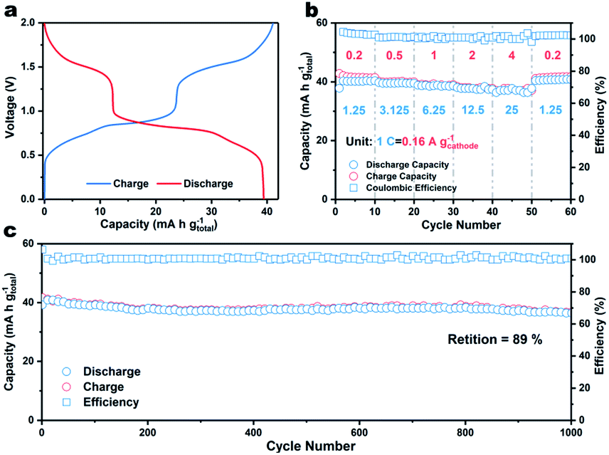 | ||
| Fig. 4 (a) Galvanostatic discharge/charge curves of AFKIB at a current density of 0.2 A g−1. (b) Rate performance of AFKIB at current rates from 1.25 to 25C (1C = 160 mA gcathode−1). (c) Cycling performance of AFKIB at 12.5C for 1000 cycles. | ||
In summary, we proposed a KFSI-based WiSE electrolyte for aqueous K-ion batteries. Due to the high solubility of KFSI in water, the introduction of KFSI yielded a decreased quantity of free water molecules, resulting in suppressed hydrogen/oxygen evolutions and a broader stable electrochemical window of 3.97 V. The paucity of free water also solved the β-PTCDA dissolution problem. In addition, the use of concentrated KFSI also decreased the reaction resistance as well as charge-transfer resistance, leading to improved kinetics. Thus, β-PTCDA shows an excellent capacity of 109 mA h g−1 at 8 A g−1 and a lifespan of 500 cycles at 2 A g−1. Furthermore, an aqueous full battery assembled with a KFHCF cathode shows good rate capability and long lifespan, suggesting both the electrolyte and battery system to have application potential in mid- to large-scale energy storage.
Conflicts of interest
There are no conflicts to declare.Acknowledgements
This work was supported by the NSFC (51572107), the Joint Project between Jilin Province and Jilin University (SXGJQY2017-10), the Science and Technology Development Project, Jilin Province (Grant No. 20180101211JC and 20190701020GH) and the Fundamental Research Funds for the Central Universities.Notes and references
- J. Huang, Z. Guo, Y. Ma, D. Bin, Y. Wang and Y. Xia, Small Methods, 2019, 3, 1800272 CrossRef.
- D. Bin, F. Wang, A. G. Tamirat, L. Suo, Y. Wang, C. Wang and Y. Xia, Adv. Energy Mater., 2018, 8, 1703008 CrossRef.
- V. Verma, S. Kumar, W. Manalastas, R. Satish and M. Srinivasan, Adv. Sustainable Syst., 2019, 3, 1800111 CrossRef.
- Y. Feng, Q. Zhang, S. Liu, J. Liu, Z. Tao and J. Chen, J. Mater. Chem. A, 2019, 7, 8122–8128 RSC.
- C. Wu, S. Gu, Q. Zhang, Y. Bai, M. Li, Y. Yuan, H. Wang, X. Liu, Y. Yuan, N. Zhu, F. Wu, H. Li, L. Gu and J. Lu, Nat. Commun., 2019, 10, 73 CrossRef PubMed.
- J. Xie and Q. Zhang, Small, 2019, 15, 1805061 CrossRef PubMed.
- D. Su, A. McDonagh, S. Z. Qiao and G. Wang, Adv. Mater., 2017, 29, 1604007 CrossRef PubMed.
- L. Jiang, Y. Lu, C. Zhao, L. Liu, J. Zhang, Q. Zhang, X. Shen, J. Zhao, X. Yu, H. Li, X. Huang, L. Chen and Y.-S. Hu, Nat. Energy, 2019, 4, 495–503 CrossRef CAS.
- X. Zou, P. Xiong, J. Zhao, J. Hu, Z. Liu and Y. Xu, Phys. Chem. Chem. Phys., 2017, 19, 26495–26506 RSC.
- H. Kim, J. C. Kim, M. Bianchini, D.-H. Seo, J. Rodriguez-Garcia and G. Ceder, Adv. Energy Mater., 2018, 8, 1702384 CrossRef.
- J. Wang, J.-G. Wang, H. Liu, C. Wei and F. Kang, J. Mater. Chem. A, 2019, 7, 13727–13735 RSC.
- Q. Li, Q. Zhang, C. Liu, Z. Zhou, C. Li, B. He, P. Man, X. Wang and Y. Yao, J. Mater. Chem. A, 2019, 7, 12997–13006 RSC.
- L. Suo, O. Borodin, T. Gao, M. Olguin, J. Ho, X. Fan, C. Luo, C. Wang and K. Xu, Science, 2015, 350, 938–943 CrossRef CAS PubMed.
- C. Zhang, J. Holoubek, X. Wu, A. Daniyar, L. Zhu, C. Chen, D. P. Leonard, I. A. Rodriguez-Perez, J. X. Jiang, C. Fang and X. Ji, Chem. Commun., 2018, 54, 14097–14099 RSC.
- L. Suo, O. Borodin, W. Sun, X. Fan, C. Yang, F. Wang, T. Gao, Z. Ma, M. Schroeder, A. von Cresce, S. M. Russell, M. Armand, A. Angell, K. Xu and C. Wang, Angew Chem Int Ed Engl, 2016, 55, 7136–7141 CrossRef CAS PubMed.
- L. Suo, O. Borodin, Y. Wang, X. Rong, W. Sun, X. Fan, S. Xu, M. A. Schroeder, A. V. Cresce, F. Wang, C. Yang, Y.-S. Hu, K. Xu and C. Wang, Adv. Energy Mater., 2017, 7, 1701189 CrossRef.
- D. P. Leonard, Z. Wei, G. Chen, F. Du and X. Ji, ACS Energy Lett., 2018, 3, 373–374 CrossRef CAS.
- L. Fan, R. Ma, J. Wang, H. Yang and B. Lu, Adv. Mater., 2018, 30, 1805486 CrossRef PubMed.
- Y. N. Chen, W. Luo, M. Carter, L. H. Zhou, J. Q. Dai, K. Fu, S. Lacey, T. Li, J. Y. Wan, X. G. Han, Y. P. Bao and L. B. Hu, Nano Energy, 2015, 18, 205–211 CrossRef CAS.
- L. Q. Deng, X. G. Niu, G. S. Ma, Z. Yang, L. Zeng, Y. J. Zhu and L. Guo, Adv. Funct. Mater., 2018, 28, 1800670 CrossRef.
- J. Zhao, X. Zou, Y. Zhu, Y. Xu and C. S. Wang, Adv. Funct. Mater., 2016, 26, 8103–8110 CrossRef CAS.
Footnote |
| † Electronic supplementary information (ESI) available. See DOI: 10.1039/c9se00545e |
| This journal is © The Royal Society of Chemistry 2020 |