High-performance spinel LiMn2O4@carbon core–shell cathode materials for Li-ion batteries†
Vadivel
Selvamani
ab,
Nutthaphon
Phattharasupakun
ab,
Juthaporn
Wutthiprom
ab and
Montree
Sawangphruk
 *ab
*ab
aCentre of Excellence for Energy Storage Technology (CEST), Vidyasirimedhi Institute of Science and Technology, Rayong 21210, Thailand
bDepartment of Chemical and Biomolecular Engineering, School of Energy Science and Engineering, Vidyasirimedhi Institute of Science and Technology, Rayong 21210, Thailand. E-mail: montree.s@vistec.ac.th
First published on 23rd May 2019
Abstract
A core–shell-type spinel LiMn2O4/carbon composite was synthesized by a simple and cost-effective mechanofusion method (dry particle coating) with a highly uniform coating. Electrochemical characterizations demonstrated that the surface-engineered core–shell-like material exhibited superior rate retention as well as cycling stability than pristine LMO due to improved intrinsic conductivity and easy electrolyte access. As a result, in the half-cell configuration, the core–shell carbon composite delivered reversible specific capacity of 103 mA h g−1 after 1000 cycles at 0.75C with 82% capacity retention; however, the pristine material showed specific capacity of 78 mA h g−1 and 76% capacity retention after 600 cycles. Similarly, in the full cell studies, the core–shell material exhibited 70% capacity retention, whereas the pristine material retained only 53% after 1000 cycles at 0.1 A g−1. The spinel LiMn2O4@carbon core–shell material obtained by the mechanofusion method may be a practical cathode material in high-performance lithium-ion batteries toward high energy applications.
Introduction
The modern era completely relies on uninterrupted power supply to fulfil the current energy requirements. Among various energy storage systems, secondary lithium-ion batteries (LIBs) have become a vital part due to their high energy densities. However, intensive research is still required to upgrade the existing technologies. Considering the various components in LIBs, the cathode is one of the main components determining the overall specific capacity. The face-centred cubic (fcc) spinel LiMn2O4 (LMO) has emerged as an attractive and potential alternative candidate to toxic LiCoO2 for high energy applications because of its relative abundance, low cost, and environmental safety. Although LMO has several advantages, it undergoes immense polarization as well as rapid capacity degradation at high rate cycling.1 Recent studies manifest that the strong interaction between the electrolyte and de-lithiated cathode can lead to rapid Mn3+ dissolution during the charging process. Furthermore, the electronic configuration of Mn3+ cations (t32g–e1g) within the [MnO6] crystal lattice causes Jahn–Teller distortion (cubic to tetragonal transition) accompanied with 6.5% increase in the unit cell volume, destructing its structural integrity and thus resulting in rapid capacity fading.2,3 Besides, the dissolved manganese ions diffuse to the lithiated anode and get self-reduced, thereby diminishing the service life of the battery.4 Various strategies have already been proposed to alleviate these detrimental issues such as heteroatom doping, surface blocking coatings, and functional electrolyte additives.5As compared with other attempts, surface engineering is simple and is the most promising technique to improve the kinetics and long-term cycling performance. In partial cationic/anionic substitution, the diverse stoichiometry can reduce the over-oxidation of Mn and ensure minimal capacity fading.6,7 However, the loss of the original specific capacity of the active material on doping with an electrochemically inactive cation (e.g., Al3+ and Ti4+) is inevitable. The use of electrochemically active dopants such as Ni2+ and Co2+ leads to safety issues due to their high activity.8 Similarly, reduction in the particle size has also been proposed to achieve high rate capability by increasing the contact area and reducing the diffusion path length.9 However, the high porosity and poor packing density of these nano-grains tend to reduce the overall cell capacity. Besides, the loosely bound nano-particles may penetrate through the microporous separator, thus leading to a short circuit.10 Hence, surface modification has been widely investigated and recommended to suppress Mn dissolution without compromising the cell capacity.2
Of late, surface modification with a thin metal oxide/phosphate coating has been shown to provide a barrier layer for the active material against hydrogen fluoride attack in the electrolyte. Many amphoteric metal oxide coatings have already been investigated for various cathode materials.11 For instance, amorphous Al2O3 has been widely studied as a coating material but has poor stability. It can be converted to the corresponding metal fluorides by the scavenged HF. Besides, metal oxides have poor electronic conductivity, limiting the overall kinetics of electron transfer.12 Furthermore, carbon-based surface coatings have received much attention owing to their high electronic conductivity, low cost, and abundance.13 Besides, they can provide a continuous pathway for electron conduction and thereby maintain the interparticle contact. Different types of carbon-based composite coatings have already been studied to improve the electrochemical performance of LMO including graphene, rGO, CNTs, and other porous carbon materials derived from organic precursors.14–16 However, the high cost and tedious synthesis process of the aforementioned carbon materials hinder the commercialization of their LMO composites. In addition, the pyrolysis-assisted synthesis of carbon coatings with organic precursors requires high-temperature annealing, leading to oxygen defects.17 Conductive Super P, a low-cost and readily available alternative carbon material, makes this composite practically feasible. So far, most of the surface modifications have been achieved by the wet chemical method and atomic layer deposition. Nevertheless, the former requires an additional processing step and the latter is expensive as well as difficult to scale up.
Herein, mechanothermal fusion, a simple and cost-effective solvent-free processing method, was adopted to coat sub-micron-sized conductive carbon black over micron-sized LMO crystal facets. The carbon coating obtained by the mechanofusion method, a dry particle coating without using any liquids, was more uniform and intact than that obtained by planetary milling, where the impact and centrifugal forces mainly depend on the size of the milling ball and the rotation speed. Besides, grinding at high energy leads to the destruction of the host with poor dispersion of the guest molecules; moreover, milling at low energy/speed results in uniform dispersion with poor adhesion. However, in the mechanofusion method, the material is initially subjected to a strong centrifugal force under high-speed rotation of the inner rotating chamber, followed by strong shear and compression forces at the narrow gap between the chamber wall and rotor head. Besides, the scraper continuously scrapes off the adhered particles on the inner wall and helps re-disperse them, thus ensuring a uniform intrinsic coating by fusing the guest molecules over the host.18 The present study suggests that the use of the mechanical force-reinforced carbon coating obtained by the mechanofusion method is an alternative and practically feasible approach to attain improved cycle life as well as rate performance.
Experimental and discussion
Synthesis of core–shell lithium-manganese oxide (LMOCS)
A core–shell-type LMO/carbon composite was synthesized by employing the NOBILTA (NOM-130, Hosokawa Micron Corporation, Japan) mechano-fusion system equipped with cold water circulation. Briefly, 80 g of vacuum-dried LiMn2O4 (GELON) and 20 g Super P (TIMCAL) premixed material were loaded into the dry processing vessel armed with a press head and scraper. The mechano-fusion process was carried out by controlled ramping of the rotor speed to 5000 rpm for a stipulated period of 30 min.Physical characterization
X-ray diffraction patterns were recorded using a Bruker (D8 Advance) XRD diffractometer with Ni-filtered Cu-Kα radiation (1.5406 Å). The surface topography of the core–shell material was studied by employing a scanning electron microscope (JEOL, JSM 7610-F) and high-resolution transmission electron microscope (JEOL, JEM-ARM200F) with CCD imaging. The elemental composition of the material was investigated by X-ray photoelectron spectroscopy (XPS, Kratos Axis Ultra DLD) using monochromatic Al-Kα (1486.7 eV) as the excitation source and C 1s (284.6 eV) for a reference binding energy. Raman spectra were obtained with a dispersive Raman spectrometer (SENTERRA, Bruker) with an excitation wavelength of 532 nm. The carbon contents of the mechano-fused core–shell and the physically blended carbon composite materials were evaluated with a thermogravimetric analyzer (Linseis STA PT1600) in an oxygen atmosphere at a heating rate of 10 °C min−1.Electrochemical characterization
The electrochemical performance of the core–shell-type carbon composite of the LMO material was evaluated by employing the standard CR-2032-type coin cells and compared with that of a pristine LMO/carbon composite containing the same amount of carbon obtained by physical blending. The working electrodes were prepared by mixing 90 wt% LMO-carbon composites with 10 wt% of PVDF binder using NMP dispersant, followed by tape-casting over the surface-cleaned aluminium foil according to the required thickness. Likewise, the graphitic MCMB electrode material was prepared in the weight ratio of 80![[thin space (1/6-em)]](https://www.rsc.org/images/entities/char_2009.gif) :
:![[thin space (1/6-em)]](https://www.rsc.org/images/entities/char_2009.gif) 10
10![[thin space (1/6-em)]](https://www.rsc.org/images/entities/char_2009.gif) :
:![[thin space (1/6-em)]](https://www.rsc.org/images/entities/char_2009.gif) 10, corresponding to the active material, Super P, and PVDF in the NMP dispersant and coated over the copper foil. The vacuum-dried foils were calendered and cut into small discs, and stored in the glove box, where the moisture and oxygen levels were maintained at less than 0.1 ppm (MBRAUN, UNILAB). For the half-cell studies, a reasonable active material loading in the range of 2.0 ± 0.2 mg cm−2 was chosen. During the coin cell fabrication, the polypropylene separator soaked in an electrolyte (1.0 M LiPF6 in EC
10, corresponding to the active material, Super P, and PVDF in the NMP dispersant and coated over the copper foil. The vacuum-dried foils were calendered and cut into small discs, and stored in the glove box, where the moisture and oxygen levels were maintained at less than 0.1 ppm (MBRAUN, UNILAB). For the half-cell studies, a reasonable active material loading in the range of 2.0 ± 0.2 mg cm−2 was chosen. During the coin cell fabrication, the polypropylene separator soaked in an electrolyte (1.0 M LiPF6 in EC![[thin space (1/6-em)]](https://www.rsc.org/images/entities/char_2009.gif) :
:![[thin space (1/6-em)]](https://www.rsc.org/images/entities/char_2009.gif) DEC, 1
DEC, 1![[thin space (1/6-em)]](https://www.rsc.org/images/entities/char_2009.gif) :
:![[thin space (1/6-em)]](https://www.rsc.org/images/entities/char_2009.gif) 1 by vol) was sandwiched between the coated electrode and lithium chip. After a quasi-equilibration time at room temperature, the assembled cell was subjected to electrochemical characterization using a Neware (GN-4008-SCT) battery life cycle tester and Autolab workstation. The heterogeneous rate constant (k0) was calculated by employing a rotating disc electrode (RDE) in the conventional battery electrolyte. The working electrode was prepared by drop-casting the active material dispersed ink over the glassy carbon rotating disk electrode (RDE). We recorded EIS at different rotation speeds from 0 to 5000 rpm vs. lithium metal by holding the potential at 4.2 V (a three-electrode setup). The counter and reference lithium metals were periodically changed and allowed to attain equilibrium for a period of 60 min each rpm.
1 by vol) was sandwiched between the coated electrode and lithium chip. After a quasi-equilibration time at room temperature, the assembled cell was subjected to electrochemical characterization using a Neware (GN-4008-SCT) battery life cycle tester and Autolab workstation. The heterogeneous rate constant (k0) was calculated by employing a rotating disc electrode (RDE) in the conventional battery electrolyte. The working electrode was prepared by drop-casting the active material dispersed ink over the glassy carbon rotating disk electrode (RDE). We recorded EIS at different rotation speeds from 0 to 5000 rpm vs. lithium metal by holding the potential at 4.2 V (a three-electrode setup). The counter and reference lithium metals were periodically changed and allowed to attain equilibrium for a period of 60 min each rpm.
Results and discussion
The surface topographies of Super-P, pristine LMO, physically blended LMO (PLMO) with carbon, and core–shell LMO (LMOCS) obtained by mechanothermal fusion were examined by using FE-SEM (Fig. 1). As seen in Fig. 1a and b, Super P and pristine LMO show uniformly distributed well-defined interconnected porous carbon threads and crystalline octahedral phases with smooth surfaces, respectively. Similarly, the physically blended material (Fig. 1c) showed incomplete carbon coatings with large exposure of the pristine LMO crystalline facets. However, the mechanothermal-fused material exhibited complete wrapping of LMO with conductive carbon particles similar to a core–shell architecture (Fig. 1d).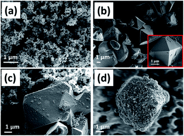 | ||
| Fig. 1 FE-SEM images of (a) Super P, (b) pristine LMO without carbon, (c) physically blended LMO with carbon (PLMO), and (d) mechano-fused LMO-carbon core shell (LMOCS). | ||
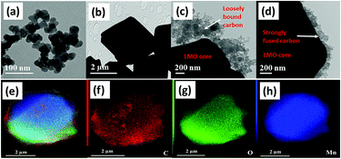
The HR-TEM images of Super P, pristine LMO without carbon, physically blended LMO with the carbon composite, and mechano-fused LMOCS materials are displayed in Fig. 2a–d. As depicted in this figure, the physically blended LMO-carbon composite exhibits weak adherence of carbon that detaches from the surface during sonication; however, the strong centrifugal force coupled with shear and compression forces could fuse the nano-sized carbon particles over LMO. Furthermore, the strong mechanical force ensured a uniform carbon coating of about 70–90 nm thickness with effective adherence (Fig. 2d). It is worth mentioning that the carbon coating not only helped improve the electrical conductivity of the material but also prevented a direct contact with the electrolyte, thereby minimizing metal dissolution. Furthermore, the homogeneous distribution of the constituent elements present in the core–shell material was elucidated by scanning transmission electron microscopy-energy dispersive spectroscopy (STEM-EDS) mapping presented in Fig. 2e–h, which definitively demonstrated the uniformity of the carbon coating.
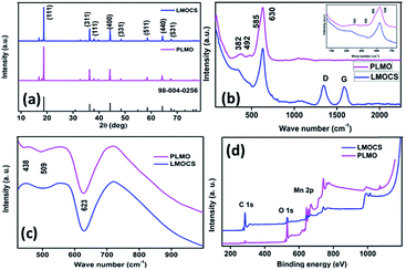
Fig. 3a signifies the XRD patterns of the core–shell material synthesized by mechanothermal fusion as well as pristine LMO; all the intrinsic peaks are indexed to the cubic phase of LiMn2O4 possessing the Fd![[3 with combining macron]](https://www.rsc.org/images/entities/char_0033_0304.gif) m space group (JCPDS. no: 98-005-0256). No obvious or subtle changes in the peak position as well as new peaks related to carbon could be observed after fusion with Super P, which might be due to its small amount and amorphous nature. The typical Raman signatures of pristine as well as core–shell LMO are shown in Fig. 3b and the inset image. A strong, broad peak obtained at 630 cm−1 along with a shoulder peak at 585 cm−1 is due to the A1g and F2g modes of the symmetric Mn–O stretching in the octahedral MnO6 moiety and could be related to its high electronic conductivity.19 The existence of polyhedral distortion in the crystal structure may alter the cation–anion bond length, which also leads to peak broadening.6 Also, small peaks observed at 492 and 382 cm−1 related to the F2g and Eg symmetries, respectively, accounted for the Li–O vibration.20 It can be seen from the Raman spectra that there is no obvious peak shift even after the mechanothermal fusion with conductive carbon. However, two additional peaks are observed for the core–shell material at 1343 and 1585 cm−1, which might correspond to the out-of-plane (A1g vibrational mode) and in-plane (E2g vibrational mode) Raman excitations of the disordered (D) and graphitic (G) bands derived from Super P. The intensity ratio (ID/IG) of the carbon material could be directly indexed to the degree of disorder and was found to be 1.08, which signified its low-level graphitization. The vibrational mode of the cation motion in the cubic structure is sensitive and strongly related to the point group symmetry of the neighbouring oxygen host. Hence, FT-IR analysis helps probe the local environment of the cation in three-dimensional spinel structures. As depicted in Fig. 3c, the strong and weak broad peaks obtained at 623 and 509 cm−1 are ascribed to the asymmetric stretching of MnO6 and the band at 438 cm−1 with very low intensity is related to the vibrational frequency of Li+ in the neighbouring O2− host.
m space group (JCPDS. no: 98-005-0256). No obvious or subtle changes in the peak position as well as new peaks related to carbon could be observed after fusion with Super P, which might be due to its small amount and amorphous nature. The typical Raman signatures of pristine as well as core–shell LMO are shown in Fig. 3b and the inset image. A strong, broad peak obtained at 630 cm−1 along with a shoulder peak at 585 cm−1 is due to the A1g and F2g modes of the symmetric Mn–O stretching in the octahedral MnO6 moiety and could be related to its high electronic conductivity.19 The existence of polyhedral distortion in the crystal structure may alter the cation–anion bond length, which also leads to peak broadening.6 Also, small peaks observed at 492 and 382 cm−1 related to the F2g and Eg symmetries, respectively, accounted for the Li–O vibration.20 It can be seen from the Raman spectra that there is no obvious peak shift even after the mechanothermal fusion with conductive carbon. However, two additional peaks are observed for the core–shell material at 1343 and 1585 cm−1, which might correspond to the out-of-plane (A1g vibrational mode) and in-plane (E2g vibrational mode) Raman excitations of the disordered (D) and graphitic (G) bands derived from Super P. The intensity ratio (ID/IG) of the carbon material could be directly indexed to the degree of disorder and was found to be 1.08, which signified its low-level graphitization. The vibrational mode of the cation motion in the cubic structure is sensitive and strongly related to the point group symmetry of the neighbouring oxygen host. Hence, FT-IR analysis helps probe the local environment of the cation in three-dimensional spinel structures. As depicted in Fig. 3c, the strong and weak broad peaks obtained at 623 and 509 cm−1 are ascribed to the asymmetric stretching of MnO6 and the band at 438 cm−1 with very low intensity is related to the vibrational frequency of Li+ in the neighbouring O2− host.
Fig. S1† displays the TGA profiles of pristine LMO without carbon, physically blended LMO-carbon (PLMO), and mechano-fused LMOCS composites measured in an oxygen atmosphere with a heating rate of 10 °C min−1. The core–shell material exhibited 2.5 wt% weight loss before 400 °C, followed by an abrupt loss of about 17.5 wt% between 400 and 550 °C; in contrast, pristine LMO showed an overall weight loss of 1.5 wt% during the whole heating process. The initial weight loss was related to the residual moisture and other volatiles, while the latter could be attributed to the amount of carbon present in the core–shell material. Similarly, the physically blended composite material exhibited 20.0% weight loss related to its carbon content from 400 to 550 °C. The small amount of carbon loss during the synthesis of core–shell LMO by the mechano-fusion method was obvious. XPS was also employed to investigate the surface composition, chemical binding energy, and oxidation states of the elements, as shown in Fig. 3d and 4. As depicted in the survey spectrum in Fig. 3d, three major peaks at 284.6, 530 and 642 as well as 654 eV are related to C 1s, O 1s, and Mn 2p, respectively. All the peaks are deconvoluted with Gaussian fitting to understand the bonding environment (Fig. 4). Interestingly, no change in the binding energy was observed after mechanothermal fusion, indicating the similar oxidation state of manganese. The high-resolution spectrum of Mn 2p consists of two major peaks related to the oxidation state of Mn 2p3/2 as well as Mn 2p1/2, and the calculated binding energy difference is 11.7 eV, which can arise due to the characteristic spin–orbit splitting (ΔE) of Mn–O.12,16,21
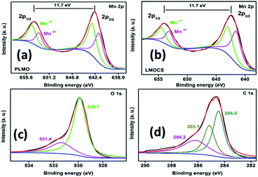 | ||
| Fig. 4 Narrow-scan XPS spectra: (a and b) deconvoluted spectra of Mn 2p orbitals for LMOCS and PLMO, (c) O 1s and (d) C 1s orbitals of LMOCS. | ||
Fig. 4a represents the deconvoluted spectrum of pristine LMO and the peaks observed at 641.6 and 653.6 eV are associated with Mn3+, while the Mn4+ peaks are located at 642.9 and 654.6 eV. The deconvoluted spectrum of core–shell LMO (Fig. 4b) shows two peaks located at 641.3 and 653.2 eV, corresponding to the binding energy of Mn3+, whereas the Mn4+ peaks are observed at 642.7 and 654.5 eV. The decrease in the binding energy of the core–shell material could be related to the modification of the surface with carbon. The deconvoluted O 1s spectrum displayed in Fig. 4c indicates two peaks at 529.7 and 531.4 eV owing to the lattice oxygen (Mn–O–Mn) and surface-adsorbed species, respectively. Similarly, the C 1s spectrum (Fig. 4d) was deconvoluted to three peaks at about 284.5, 285.1, and 286.2 eV, corresponding to the C![[double bond, length as m-dash]](https://www.rsc.org/images/entities/char_e001.gif) C, C–C, and C–O groups.
C, C–C, and C–O groups.
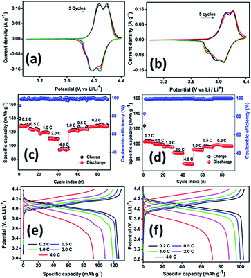
Fig. 5a and b show the comparison of typical cyclic voltammograms containing five consecutive cycles recorded for the core–shell material and PLMO, respectively, at a sweep rate of 0.1 mV s−1 in the potential region from 3.0 to 4.4 V. Both the samples exhibited two similar pairs of characteristic redox peaks associated with the reversible insertion/extraction of the lithium ions in/from the spinel moiety. The core–shell material exhibited the first redox peak at 4.09/3.95 V, corresponding to the reversible extraction of lithium ions from one-half of the tetrahedral sites; another peak at 4.18/4.09 V was related to the extraction/insertion of lithium ions from/in the rest of the tetrahedral sites. Similarly, the pristine material also showed two redox peaks at 4.12/3.98 and 4.21/4.07 V during the first cycle. It is worth noting here that a slight variation in the peak intensity was observed between the first and the second stage of extraction/insertion, which could be related to the interaction between Li–Li. As compared to the first stage, the second stage lithium extraction is energetically more favourable and shows improved diffusion.11 From the second cycle onwards, all the cycles overlapped with each other with minor peak shifts. A small shoulder peak was observed at 3.87 V due to the slight structural rearrangement during cycling, which stabilized within a few cycles.22 As compared to the result for PLMO, the redox peak intensities were almost equal for the core–shell material, which ensured its good reversibility and high coulombic efficiency. Furthermore, the high current response of the core–shell material could be related to its high conductivity. Fig. 5c–f depict the rate performance and cycling profiles at different C-rates for core–shell LMO and PLMO, respectively. The core–shell material initially delivered specific charge capacity of about 140 mA h g−1, while its corresponding discharge capacity was 129 mA h g−1 at 0.2C in the formation cycle, resulting in 92% coulombic efficiency. From the second cycle onwards, the capacity was stabilized and maintained for the ten studied cycles. Perceptible average discharge capacities of about 124, 118, 111, and 96 mA h g−1 were obtained when the current was increased from 0.5C to 1.0C, 2.0C, and 4.0C, respectively. The capacity retention behaviour was further evaluated for the high rate cycled cell by switching back to low current rates, i.e., 1.0, 0.5, and 0.2C, and the average specific capacities returned to 120, 125, and 129 mA h g−1, respectively. Similarly, the pristine material exhibited charge and discharge capacities of about 123 and 103 mA h g−1, respectively, in the formation cycle at 0.2C with 84% initial coulombic efficiency. As the C-rate increased from 0.5 to 1.0, 2.0, and 4.0C, the corresponding specific discharge capacities decreased to 100, 96, 88, and 73 mA h g−1. When the cell was again subjected to low C rates from 1.0 to 0.5 and 0.2C, the average discharge capacities retained were 92, 96, and 99 mA h g−1, respectively. The electrode polarisation increased significantly at high C-rates and resulted in low specific capacities, as shown in the voltage vs. capacity comparison profile (Fig. 5e and f). At a low current rate, the reaction proceeds close to the equilibrium, whereas the improved mass transport and kinetics limit the reaction at high current rates.23 As compared with the pristine material, core–shell LMO experienced low polarisation, which could be related to its improved conductivity. Furthermore, the galvanostatic cycling profiles show a pair of pseudo-plateaus during the charging process related to lithium extraction, which is consistent with the CV curves.
Also, steady-state cycling was carried out to ensure the improved electrochemical properties of the core–shell material and the results were compared with that of PLMO at a moderate C rate of about 0.75C (Fig. 6). LMOCS (Fig. 6a) delivered specific charge and discharge capacities of about 136 and 125 mA h g−1, respectively, with 92% coulombic efficiency at the initial cycle. From the second cycle onwards, the coulombic efficiency substantially increased to above 99% and was maintained for the 1000 cycles studied. However, the specific capacity decreased gradually and attained the value of 103 mA h g−1 with 82% capacity retention. Similarly, the PLMO material (Fig. 6b) showed the initial discharge and charge capacities of about 102 and 117 mA h g−1, respectively, with 87% initial coulombic efficiency. The capacity slightly increased at the beginning, endured severe degradation, and reached 76% capacity retention (78 mA h g−1) within 600 cycles. In general, above 80% of capacity retention is applicable for practical utilization. Thus, high specific discharge capacity, appreciable long-term stability, and excellent capacity and rate retention behaviour of the core–shell material further reinforce the possibility of its practical applications. Fig. 6c and d show the steady-state cycling profiles obtained for the core–shell and pristine LMO materials at 0.75C. The electrochemical performances of different LMO composites including those obtained via surface modification and heteroatom doping have been compared and listed in Table S1.†
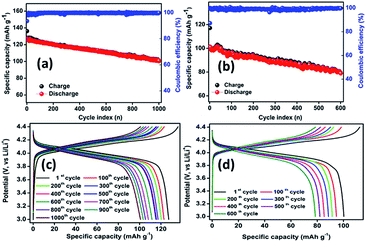 | ||
| Fig. 6 (a and b) Capacity retention as a function of cycle number along with coulombic efficiency at 0.75C; (c and d) corresponding charge/discharge cycling profiles for LMOCS and PLMO. | ||
Fig. S2† illustrates the galvanostatic steady-state cycling and the corresponding cycling profile of an MCMB half-cell cycled between 0.01 and 1.5 V at a current density of 0.1 A g−1. The material exhibited capacities of about 312 and 446 mA h g−1 for the initial charge and discharge cycles, respectively, with 71% initial coulombic efficiency. From the second cycle onwards, the coulombic efficiency substantially increased to above 99% and was maintained at this value. The capacity decreased to 295 mA h g−1 within seven cycles and recovered to a stable capacity of above 320 mA h g−1 for the 75 cycles studied. Fig. 7 depicts the galvanostatic charge/discharge cycling of core–shell and pristine LMO vs. an MCMB anode between 3.0 and 4.3 V at 0.1 A g−1. As displayed in Fig. 7a, the core–shell material initially delivers discharge capacity of about 71 mA h g−1 with 99.5%.
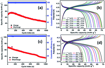 | ||
| Fig. 7 Steady-state cycling of the full cells (a) LMOCS vs. MCMB, (c) PLMO vs. MCMB; (b) and (d) respective galvanostatic charge/discharge curves at 0.75C. | ||
Coulombic efficiency after the formation cycle and reaches the value of 50 mA h g−1 after 1000 cycles with 70% capacity retention. Similarly, PLMO shows discharge capacity of 70 mA h g−1 at the beginning and that of 37 mA h g−1 after 1000 cycles with 53% capacity retention.
The heterogeneous rate constant (k0, cm s−1) was calculated for both the samples according to previously reported procedures.24–26 All the Nyquist plots were fitted providing the corresponding Randel's equivalent circuit, as shown in Fig. S4.† In turn, the circuit consists of Ohmic/contact resistance (Rs), SEI formation (Rf) parallel to capacitance, charge transfer resistance (Rct), and constant phase element (Q), followed by Warburg resistance (W). The Rct values were obtained from the circuit and substituted in the following eqn (1):
| K0 = RT/nF2ACsRct | (1) |
Fig. 8a and c display the fitted EIS results for the core–shell material and PLMO. As seen from the figure, the Rct values increase slightly on increasing the rotation speed at the delithiated state; the calculated rate constant (k0) values were in the range of 3.9–4.1 and 3.1–3.4 for the core–shell material and PLMO, respectively. Fig. 8b and d depict the corresponding Bode phase change obtained for LMOCS and PLMO at different rotating speeds. The phase angle increased on increasing the rotation speed; this was related to lithium deintercalation/intercalation, where core–shell LMO exhibited the maximum phase angles of −66 and −79 for PLMO at low frequencies. As displayed in the Nyquist plot in Fig. S3,† both the half cells show partially overlapped depressed semi-circles, followed by an inclined ramp line from high to middle and low-frequency regions. The core–shell material showed initial Rs and Rct of 7.5 and 96.8 ohm, respectively; no abrupt change in the Rs value was observed after cycling, but the Rct value was reduced to 44.8 Ohm. Similarly, the Rs and Rct values changed to 10.1 and 125.3 Ohm from 11.2 and 183.4 Ohm, respectively, after cycling for pristine LMO. The decrease in the Rs value may be attributed to the improved wetting of the electrode after cycling. It is obvious that the core–shell structure shows lower charge transfer resistance as compared with the pristine material due to the introduction of a conductive carbon matrix, which significantly increases the conductivity as well as interparticle contact. As is known, the formation of a solid-electrolyte interfacial layer tends to increase the charge transfer resistance upon cycling. However, the porous carbon coating possibly infiltrates the electrolyte at the pores and thereby reduces Rct as well as the diffusion path length.27 Besides, the densely packed Mn atoms resist dissolution upon cycling and possibly reconstruct SEI, thereby exhibiting efficient ion diffusion.28 The significant reduction of Rf and Rct after long-term cycling ensures improved electron transfer, resulting in low polarization, which partially compensates the capacity fading.29 As compared to PLMO, mechano-fused core–shell-type LMO experienced less polarization due to strong adhesion between the porous carbon and LMO crystal facets.
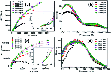 | ||
| Fig. 8 (a and c) Nyquist plots and (b and d) corresponding Bode phase angle changes for core–shell LMOCS and pristine LMO coated on GC (RDE) at different rotation speeds. | ||
The lithium-ion diffusion coefficient (DLi+) is calculated from the impedance plot of the low-frequency Warburg region by employing the following eqn (2):
| DLi+ = R2T2/2A2n4F4c2σ2 | (2) |
| Zre = Rct + Rs + σω−0.5 | (3) |
Conclusions
In summary, a facile, dense, and stable carbon coating on LMO, the cathode of a lithium-ion battery, was obtained by a solvent-free mechanofusion method. The repeated strong centrifugal force and high shear as well as compression forces ensured uniform carbon coatings. This inherently coated material showed improved conductivity by interparticle contact but no direct exposure of the core material to the electrolyte, thus ensuring minimal active metal dissolution and enabling an improved electrochemical performance. LMOCS delivered specific charge and discharge capacities of about 140 and 129 mA h g−1, respectively, with 92% coulombic efficiency at 0.2C in the initial cycle. Such a modified material exhibited a remarkably improved rate and stable cycling performance in both the half and full cell configurations.Conflicts of interest
The authors declare no competing financial interest.Acknowledgements
This work was financially supported by the Thailand Research Fund and Vidyasirimedhi Institute of Science and Technology (RSA6180031) as well as the Energy Policy and Planning Office (EPPO), Ministry of Energy, Thailand. Support from the Frontier Research Centre at VISTEC is also acknowledged. V. S. would like to thank a postdoctoral fellowship from VISTEC.References
- C. M. Sim, S. H. Choi and Y. C. Kang, Chem. Commun., 2013, 49, 5978 RSC.
- J. Zeng, M. Li, X. Li, C. Chen, D. Xiong, L. Dong, D. Li, A. Lushington and X. Sun, Appl. Surf. Sci., 2014, 317, 884–891 CrossRef CAS.
- H. Xia, Z. Luo and J. Xie, Prog. Nat. Sci.: Mater. Int., 2012, 22, 572–584 CrossRef.
- N. S. Choi, J. G. Han, S. Y. Ha, I. Park and C. K. Back, RSC Adv., 2015, 5, 2732–2748 RSC.
- P. Xue, D. Gao, S. Chen, S. Zhao, B. Wang and L. Li, RSC Adv., 2014, 4, 52624–52628 RSC.
- S. R. S. Prabaharan, S. S. Michael and C. Julien, Int. J. Inorg. Mater., 1999, 1, 21–27 CrossRef CAS.
- Q. Jiang, D. Liu, H. Zhang and S. Wang, J. Phys. Chem. C, 2015, 119, 28776–28782 CrossRef CAS.
- J. Lu, C. Zhan, T. Wu, J. Wen, Y. Lei, A. J. Kropf, H. Wu, D. J. Miller, J. W. Elam, Y.-K. Sun, X. Qiu and K. Amine, Nat. Commun., 2014, 5, 5693 CrossRef CAS PubMed.
- E. A. Velásquez, D. P. B. Silva, J. B. Falqueto, J. Mejía-López, N. Bocchi, R. del Rio, J. Mazo-Zuluaga, R. C. Rocha-Filho and S. R. Biaggio, J. Mater. Chem. A, 2018, 6, 14967–14974 RSC.
- W. Sun, H. Liu, T. Peng, Y. Liu, G. Bai, S. Kong, S. Guo, M. Li and X.-Z. Zhao, J. Mater. Chem. A, 2015, 3, 8165–8170 RSC.
- S. Jayaraman, V. Aravindan, P. Suresh Kumar, W. C. Ling, S. Ramakrishna and S. Madhavi, Chem. Commun., 2013, 49, 6677 RSC.
- H.-Q. Wang, F.-Y. Lai, Y. Li, X.-H. Zhang, Y.-G. Huang, S.-J. Hu and Q.-Y. Li, Electrochim. Acta, 2015, 177, 290–297 CrossRef CAS.
- H. Li and H. Zhou, Chem. Commun., 2012, 48, 1201–1217 RSC.
- B. Lin, Q. Yin, H. Hu, F. Lu and H. Xia, J. Solid State Chem., 2014, 209, 23–28 CrossRef CAS.
- H. Xia, K. R. Ragavendran, J. Xie and L. Lu, J. Power Sources, 2012, 212, 28–34 CrossRef CAS.
- P. R. Ilango, K. Prasanna, S. J. Do, Y. N. Jo and C. W. Lee, Sci. Rep., 2016, 6, 2–10 CrossRef PubMed.
- M.-J. Lee, E. Lho, P. Bai, S. Chae, J. Li and J. Cho, Nano Lett., 2017, 17, 3744–3751 CrossRef CAS PubMed.
- L. Zheng, T. D. Hatchard and M. N. Obrovac, MRS Commun., 2018, 1–6 Search PubMed.
- Y. Wei, K. W. Nam, K. B. Kim and G. Chen, Solid State Ionics, 2006, 177, 29–35 CrossRef CAS.
- S. Zhao, Y. Bai, Q. Chang, Y. Yang and W. Zhang, Electrochim. Acta, 2013, 108, 727–735 CrossRef CAS.
- D. Y. Sin, B. R. Koo and H. J. Ahn, J. Alloys Compd., 2017, 696, 290–294 CrossRef CAS.
- X. Zhao, M. V. Reddy, H. Liu, S. Ramakrishna, G. V. S. Rao and B. V. R. Chowdari, RSC Adv., 2012, 2, 7462–7469 RSC.
- H. W. Lee, P. Muralidharan, R. Ruffo, C. M. Mari, Y. Cui and D. K. Kim, Nano Lett., 2010, 10, 3852–3856 CrossRef CAS PubMed.
- N. Phattharasupakun, J. Wutthiprom, P. Suktha, N. Ma and M. Sawangphruk, J. Electrochem. Soc., 2018, 165, A609–A617 CrossRef CAS.
- M. Pacios, M. del Valle, J. Bartroli and M. J. Esplandiu, J. Electroanal. Chem., 2008, 619–620, 117–124 CrossRef CAS.
- J. Wutthiprom, N. Phattharasupakun and M. Sawangphruk, ACS Omega, 2017, 2, 3730–3738 CrossRef CAS.
- Y. Deng, Y. Zhou, Z. Shi, X. Zhou, X. Quan and G. Chen, J. Mater. Chem. A, 2013, 1, 8170 RSC.
- J.-S. Kim, K. Kim, W. Cho, W. H. Shin, R. Kanno and J. W. Choi, Nano Lett., 2012, 12, 6358–6365 CrossRef CAS PubMed.
- H. Liu, Y. Zhou and W. Song, J. Solid State Electrochem., 2018, 22, 2617–2622 CrossRef CAS.
Footnote |
| † Electronic supplementary information (ESI) available: TGA, XPS, GCD and EIS results. See DOI: 10.1039/c9se00274j |
| This journal is © The Royal Society of Chemistry 2019 |

