Life-cycle production optimization of hydrocarbon fields: thermoeconomics perspective
Received
12th February 2019
, Accepted 12th August 2019
First published on 12th August 2019
Abstract
We suggest alternative objective functions based on the concept of thermoeconomics (or exergoeconomics) that could be used for simultaneous maximization of economics and energy efficiency of oil-production systems. The suggested functions are evaluated for an oil reservoir, where water is injected to improve its recovery factor. We find that life-cycle optimization of water-injection projects in terms of net present value (NPV) and net cumulative exergy (NCE) leads to consistent results. We show that managing reservoirs based on a long-term objective leads to significant reduction in their CO2 footprint. For oil production by water injection, commitment to reduce CO2 emission provides an opportunity to maximize the NPV of these projects. The sustainability of water injection into hydrocarbon reservoirs is highly dependent on the volumes of the injected and produced liquids. Above a critical water cut (80% in this study), the energy efficiency of the project decreases dramatically, and its CO2 footprint increases exponentially.
1. Introduction
To mitigate the adverse impacts of global warming, the greenhouse gas concentrations, especially carbon dioxide (CO2), in the atmosphere should be stabilized in a relatively short time.1 While negative emissions (i.e., CO2 capture, utilization and/or storage, CCUS) might be needed to achieve the target concentration levels, a more viable option is to find ways to reduce the amount of (direct and indirect) CO2 emission into the atmosphere.2–9
Hydrocarbons provide much of the world's energy demand because of their abundance, ease of access and (low cost of) production, and more importantly their large (volumetric) energy density.10 However, use of hydrocarbons (or in general fossil fuels) as fuel and/or feedstock emits considerable amounts of CO2 into the atmosphere. The direct CO2 emissions from hydrocarbons are caused by combustion or oxidation reactions to release their chemical energy (or heat content). The indirect CO2 emissions arise during the exploration, drilling, extraction, transportation, and refining stages of the production cycle of the fuels, which can be 40% of the total life-cycle emissions.2,4,6 So long as there are no alternative energy sources, the direct emissions of CO2 from fossil fuels are inevitable and could not be significantly avoided. The main solution would be to capture the released CO2 and either utilize it as a chemical feedstock in other processes or store it permanently in subsurface formations.7–9,11–13 However, CO2 capture technologies are currently expensive and energy intensive.14,15 Therefore, for CO2 capture and storage (CCS) to be a more practical option, more energy-efficient capture technologies should be developed and/or the required energy during the capture and compression stages should originate from less carbon-intensive sources.16 On the other hand, the indirect emissions, which could be substantial depending on the applied extraction technology,17 can be significantly reduced by continuous optimization of the relevant processes and (quicker) integration and implementation of the energy-efficient technologies in the hydrocarbon-production systems.
The development of hydrocarbon reservoirs is generally designed to increase the financial gains over the lifetime of the selected production scheme. In the initial stages of the development, however, many (technical and non-technical) uncertainties exist, which leads to assumptions (and hence decisions) that might not necessarily hold during the operation of the field. Because of these inherent risks and uncertainties, researchers have implemented (real time) optimization schemes whose primary aim is to find a production strategy or field-development plan that yields the largest net present value (NPV) or ultimate oil recovery for the project.18–26 The simulations are performed on a large number of geological realizations (to reduce the risk of uncertainties) with the outcome to determine the optimum development option, well locations and spacing, and injection and production schemes (rates and pressures). In order to obtain the maximum NPV, the injection and production rates should be continuously monitored and if necessary altered.
The urge to reverse the global temperature rise necessitates more sustainable exploitation of hydrocarbon fields. Accordingly, the energy intensity and CO2 footprint of the production schemes should also be considered during the decision-making and optimization processes.27,28 Thus, the optimization techniques should be modified with the objective functions to reduce the energy consumption and the eventual CO2 emissions of the oil-recovery processes, from both surface and subsurface activities. Here, we adapt the concept of thermoeconomics (or exergoeconomics)29–31 and extend its application to oil extraction techniques. This approach is a common technique in the optimization of energy systems and aims at simultaneous maximization of project economics and energy efficiency.32–37
The main goal of this study is to examine the consistency between the economics and the objective to reduce CO2 emissions during the production of oil. It will be shown that, contrary to the general perception, the intent to minimize CO2 release provides an opportunity to manage oil reservoirs in a more efficient and sustainable manner, and to maximize their economic outcome. We choose waterflooding as an example because it is a widely used improved-oil-recovery (IOR) technique, in which water is injected to maintain reservoir pressure and improve the amount of recoverable oil. We use the concept of exergy and set the objective function to maximize the net cumulative exergy (NCE). Exergy is a thermodynamic concept that considers the conservation of mass, energy and irreversibilities in the system based on the second law of thermodynamics. It is a measure of quality of energy and is defined as the maximum “useful” work that can be obtained from an energy stream when brought in equilibrium with the reference environment with well-defined thermodynamic conditions.27,38–40 Exergy can be used to determine the energy-intensive components of the system, identify the losses and wastes, and finally maximize the efficiency of the system in an integrated manner.51
The structure of the paper is as follows: first, we identify the major sources of exergy gain and investment in waterflooding and provide the corresponding relations to quantify the net exergy of the process. Then, we briefly explain the optimization procedure and define the objective functions. Finally, we present the results of the optimization process accounting for CO2 emission and highlight the main conclusions of this study.
2. Net cumulative exergy (NCE)
The net cumulative exergy (NCE) is the difference between the cumulative exergy invested and the exergy gained from the system over a period of time, i.e.| | | NCE = Exgained − Exinvested | (1) |
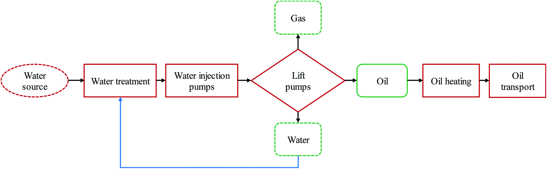
For the waterflooding process, the energy gain is mainly from the produced oil and gas since the exergy of the produced water is negligible. For simplicity we assume that the reservoir is above its bubble-point pressure and thus the amount of the produced gas is negligible. For waterflooding, the injection water is typically treated and then injected into the reservoir using pumps. The water source is assumed to be near the reservoir and hence the energy invested to transport the required water to the field is neglected. The produced liquids should be lifted from the well using pumps (gas lifting is another common method, but it is more energy intensive). The produced oil is heated at the production site and then transported to the refinery. The distance between the oil field and the refinery is considered to be 500 km. The considered system is shown in Fig. 1. In summary for the integrated surface and subsurface system of this study the NCE can be written as
| | | NCE = Exoil − (Extreatwater + Expumpwater + Exliftliquid + Exheatoil + Extransportoil) | (2) |
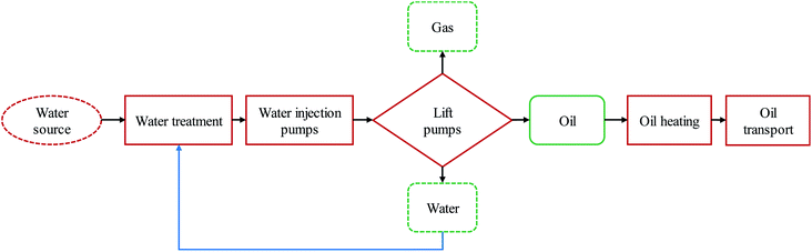 |
| | Fig. 1 The main components of the waterflooding process considered in this study. The red boxes represent the elements which require exergy investment, whereas the green boxes are the components with exergy gain. The exergy invested or gained from the boxes with the dashed line is assumed to be negligible. The analysis in this paper is up to the refinery (well to refinery gate). | |
The next section briefly describes the calculation of exergy of each subsystem.
2.1. Gained exergy (material stream)
The chemical exergy of the produced oil is its heating value and depends on its composition. The following equation is used to calculate the chemical exergy of the oil with specific gravity (SG):50| | | exoil [MJ kg−1] = 55.5 − 14.4SG | (3) |
Therefore, the cumulative exergy gained, Exgainedoil [J], is
| | | Exgainedoil = exoil × mop | (4) |
where ex
oil [J kg
−1] is the specific exergy of the oil and
mop [kg] is the cumulative mass of the produced oil. Here, we assume SG = 0.73, which results in ex
oil = 45 MJ kg
−1.
2.2. Invested exergy (work stream)
Water treatment.
Prior to injection, water should be treated to meet the specifications imposed by the reservoir properties (mainly permeability to avoid pore plugging) and surface facilities and material.41 The required exergy can be obtained from| | | Extreatwater = Ctreat × mwi | (5) |
where Extreatwater [J] is the cumulative exergy for the water treatment, Ctreat [J kg−1] is the specific energy required for water treatment and mwi [kg] is the cumulative mass of the injected water. In this work, Ctrans = 18 MJ kg−1, which is the energy required for the membrane technology.41 The same exergetic cost has been assumed for the treatment of the re-injected water.
Pumps.
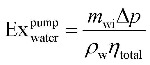
The practical pumping exergy of the injected water is calculated as| | 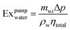 | (6) |
where Expumpwater [J] is the cumulative exergy of the pumps, mwi [kg] is the cumulative mass of injected water, ρw is the water density [kg m−3], Δp [Pa] is the pressure difference between the injection and production wells (drawdown pressure), and ηtotal is the total pump efficiency. In this study, the Δp is assumed to be constant at 2 bar, which is approximately equal to the pressure difference between the injection wells and the average reservoir pressure, based on the outcome of the simulations.
Artificial lift.
The exergy to lift the produced liquids, i.e., water and oil, from the well to the surface is calculated using the following equation,| | 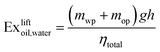 | (7) |
where Exliftoil,water is the cumulative exergy required to lift the produced liquids. Also, mwp [kg] and mop [kg] are the cumulative mass of the produced water and oil, respectively, g [m s−2] is the gravitational acceleration and h [m] is the depth of the reservoir.
Heating.
The required exergy for heating the crude oil is calculated using the following equation,| | | Exheatoil = Cheat × mop | (8) |
where Exheatoil [J] is the cumulative exergy for heating the crude oil and Cheat is the specific energy required to heat the produced oil. Here, we assumed that cp = 3 kJ kg−1 K−1 and ΔT = 20 °C, which results in Exheatoil = 60 kJ kg−1.
Transportation.
The exergy requirement for transportation of crude oil is calculated using the following expression,| | | Extransportoil = Ctrans × mop | (9) |
where Extransoil [J] is the cumulative exergy of oil transport, and Ctrans [J kg−1] is the specific energy spent on transporting oil. The exergy requirement for the transport of crude oil is assumed to be ∼188 J kg−1 km−1.42,43
Therefore, the total cumulative invested exergy can be written as follows
| | | Exinvested = Extreatwater + Expumpwater + Exliftoil,water + Exheatoil + Extransoil | (10) |
2.3. Exergy recovery factor
We define the exergy recovery factor, ExRF, as the ratio between the produced exergy corrected for material and process exergy requirements for its extraction and the gross exergy of the source,51i.e.,| | 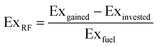 | (11) |
The exergy recovery factor assumes values between −∞ and 1 and is the measure of efficiency and sustainability of the system. In other words, 1 − ExRF is the fraction of the energy that has been “wasted” or “lost” in different components of the oil production system. The invested exergy can be used to calculate the CO2 footprint of the applied improved oil recovery technique.51 The amount of emitted CO2 depends on the CO2 footprint of the energy source. Notably, a lower exergy recovery factor does not necessarily correspond to a larger CO2 emission.
3. Objective functions
Three objective functions are used to optimize the rate of the injection and production wells to achieve a maximum economic value or energy efficiency. These functions are explained next.
3.1. Net present value (NPV)
The economic performance of a reservoir system, such as the net present value (NPV), is the most commonly used objective function for production optimization. The NPV is defined as follows (J = NPV)| | 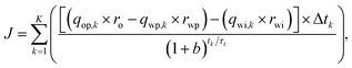 | (12) |
where qop,k [m3 day−1] is the oil production rate, qwp,k [m3 day−1] is the water production rate, qwi,k [m3 day−1] is the water injection rate, ro [$ per m3] is the unit price of the produced oil, rwp [$ per m3] is the cost of the produced water, rwi is the cost of the water injection [$ per m3], Δtk [day] is the difference between the consecutive time steps, b is the discount factor, tk [day] is the cumulative time corresponding to the time step k, and τt is the reference time period for discounting.
Table 1 shows the unit prices, which are used in eqn (12) to calculate the economic performance of the reservoir.
Table 1 Oil and water production/injection unit prices for NPV calculations
| Symbol |
Variable |
Value |
Unit |
|
r
o
|
Oil price |
126 |
$ per m3 |
|
r
wp
|
Water production cost |
19 |
$ per m3 |
|
r
wi
|
Water injection cost |
6 |
$ per m3 |
|
b
|
Discount factor |
0 |
$ per m3 |
3.2. Net cumulative exergy
The exergy-based objective function is set to the cumulative net exergy gain from the reservoir. Replacing eqn (4)–(9) in eqn (1), the NCE can be rewritten in terms of the production and injection rates as follows (V = NCE)| |  | (13) |
Table 2 shows the specific exergy values, which are used in eqn (13) to calculate the net cumulative exergy.
Table 2 Specific exergy values for NCE calculations28
| Symbol |
Variable |
Value |
Unit |
| exoil |
Oil specific exergy |
45![[thin space (1/6-em)]](https://www.rsc.org/images/entities/char_2009.gif) 000 000 |
kJ kg−1 |
|
C
heat
|
Heating specific exergy |
60 |
kJ kg−1 |
|
C
treat
|
Transportation specific exergy |
18 |
kJ kg−1 |
|
C
trans
|
Transportation specific exergy |
94 |
kJ kg−1 |
3.3. Modified NPV with CO2 emission penalty
The invested exergy can be included in the NPV definition by including a CO2-emission penalty fee. The amount of emitted CO2 is assumed to be directly related to the exergy invested to produce the hydrocarbon,| | | mCO2 = Exinvested × eCO2, | (14) |
where mCO2 [kg] is the cumulative emitted CO2, and eCO2 [kg J−1] is the unit CO2 emission factor, which depends on the source of energy. In this study it is assumed that the energy required to produce the oil is supplied by the electricity grid network. The CO2 footprint of electricity generation is different in different parts of the world depending on the fuel used in the power plants. We use eCO2 = 0.65 [kg CO2/kW he], which is the average value in the Middle East.45 Consequently, with the assumption of CO2 emission penalty, the NPV of the hydrocarbon production system can be modified as follows (F = modified NPV)| | 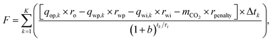 | (15) |
where rpenalty [$ per kg] is the CO2 emission fine and assumed to be 0.05 [$ per kg] in this study.44
3.4. Reactive control
Along with the optimization cases a simple reactive control scenario is also investigated, where the producers are shut in when their water cut (fraction of water in the total produced liquids) reaches 0.80.21 This value appears to be the critical water cut, above which the CO2 footprint of oil fields under waterflooding significantly increases (this will be shown later).
4. Life-cycle optimization
The optimization problems can be formulated as follows,| |  | (16) |
where f is the objective function defined in eqn (12), (13) and (15), u is the control variable vector, and umin and umax are the bound constraints. In this study water injection rates are used as the control variable and are varied between 0 and 90 m3 day−1.
Gradient-based optimization is used to iteratively optimize the objective functions, J, V and F, by changing the injection rates as the control variables, u, as shown in eqn (16). Moreover, simple bound constraints are used to ensure that the control variables (injection rates) stay within upper and lower bounds. For the present study we used an in-house reservoir simulator with adjoint functionality to calculate the gradients of the objective function.20,46,47 We used the limited-memory Broyden Fletcher Goldfarb Shanno (LBFGS) method to maximize the objective function.48
5. Model description
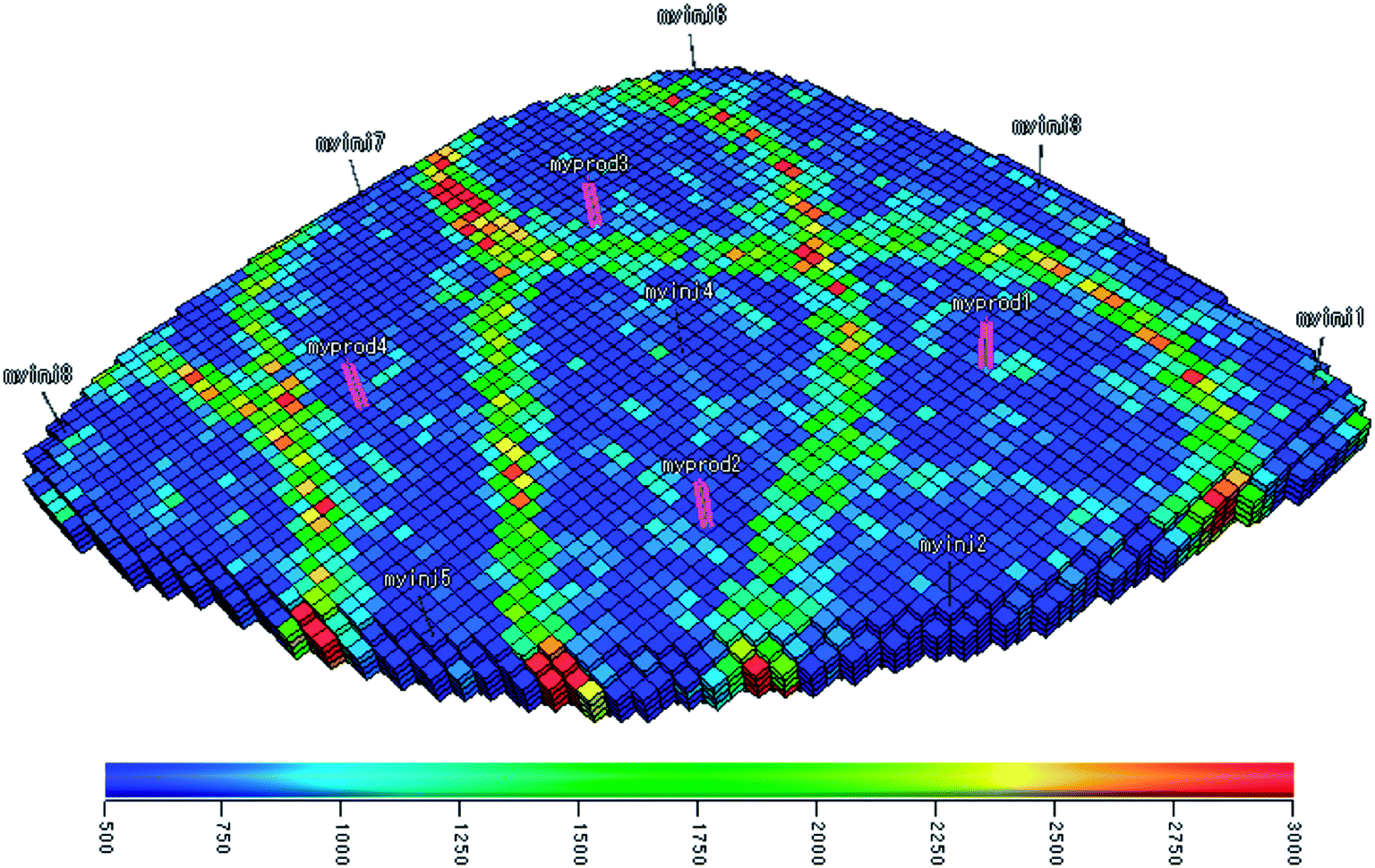
To illustrate the impact of including CO2 footprint in waterflood optimization, a synthetic reservoir case was used. The “Egg Model” is a synthetic three-dimensional channelized reservoir model, which was first introduced by van Essen et al.21 for closed-loop reservoir management purposes. The model represents a channelized depositional system with seven vertical layers and a total of 18533 active grid blocks. Each grid block is 8 by 8 m with a height of 4 m. The model consists of 8 injectors and 4 producers (see Fig. 2). The injectors have a constant flow rate and a maximum injection pressure constraint, and the producers operate at a constant bottom hole pressure. The permeability of the reservoir varies between 80 and 7000 mD and it has a uniform porosity of 0.20. The uncertainty in the permeability field and the location of the high permeability channels is characterized by 100 different realizations. Table 3 provides the fluid properties as well as Corey exponents used in this study. A detailed description of the Egg model can be found in Jansen et al.49
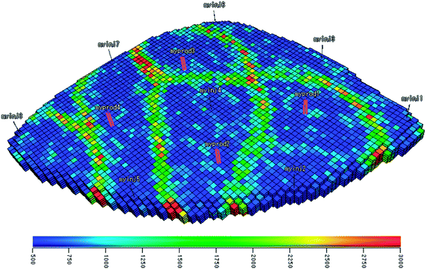 |
| | Fig. 2 Permeability of the reservoir model in millidarcy, displaying the position of the injectors (gray) and producers (purple). | |
Table 3 Reservoir and fluid properties
| Symbol |
Variable |
Value |
Unit |
|
φ
|
Porosity |
0.2 |
— |
|
c
o
|
Oil compressibility |
1.0 × 10⁻¹⁰ |
Pa−1 |
|
c
r
|
Rock compressibility |
0 |
Pa−1 |
|
c
w
|
Water compressibility |
1.0 × 10⁻¹⁰ |
Pa−1 |
|
μ
o
|
Oil dynamic viscosity |
5.0 × 10⁻¹⁰ |
Pa s |
|
μ
w
|
Water dynamic viscosity |
1.0 × 10⁻¹⁰ |
Pa s |
|
k
0ro
|
End-point relative permeability, oil |
0.80 |
— |
|
k
0rw
|
End-point relative permeability, water |
0.75 |
— |
|
n
o
|
Corey exponent, oil |
4.00 |
— |
|
n
w
|
Corey exponent, water |
3.00 |
— |
|
S
or
|
Residual oil saturation |
0.10 |
— |
|
S
wc
|
Connate-water saturation |
0.20 |
— |
|
P
init
|
Reservoir initial pressure |
400 |
bar |
|
h
|
Reservoir depth |
4000 |
m |
The initial pressure of the reservoir is 400 bar. The producers are operating at a bottom hole pressure of 395 bar and the injectors have a rate constraint varied between 1 and 79.5 m3 day−1. The reservoir is simulated for a period of 3600 days with 40 control time steps of 90 days for injection rates, which results in 40 × 8 = 320 controls, i.e. each well rate will be updated 40 times during the simulation to optimize the set objective function. Fig. 2 shows the reservoir permeability grids and the well locations.
6. Results and discussion
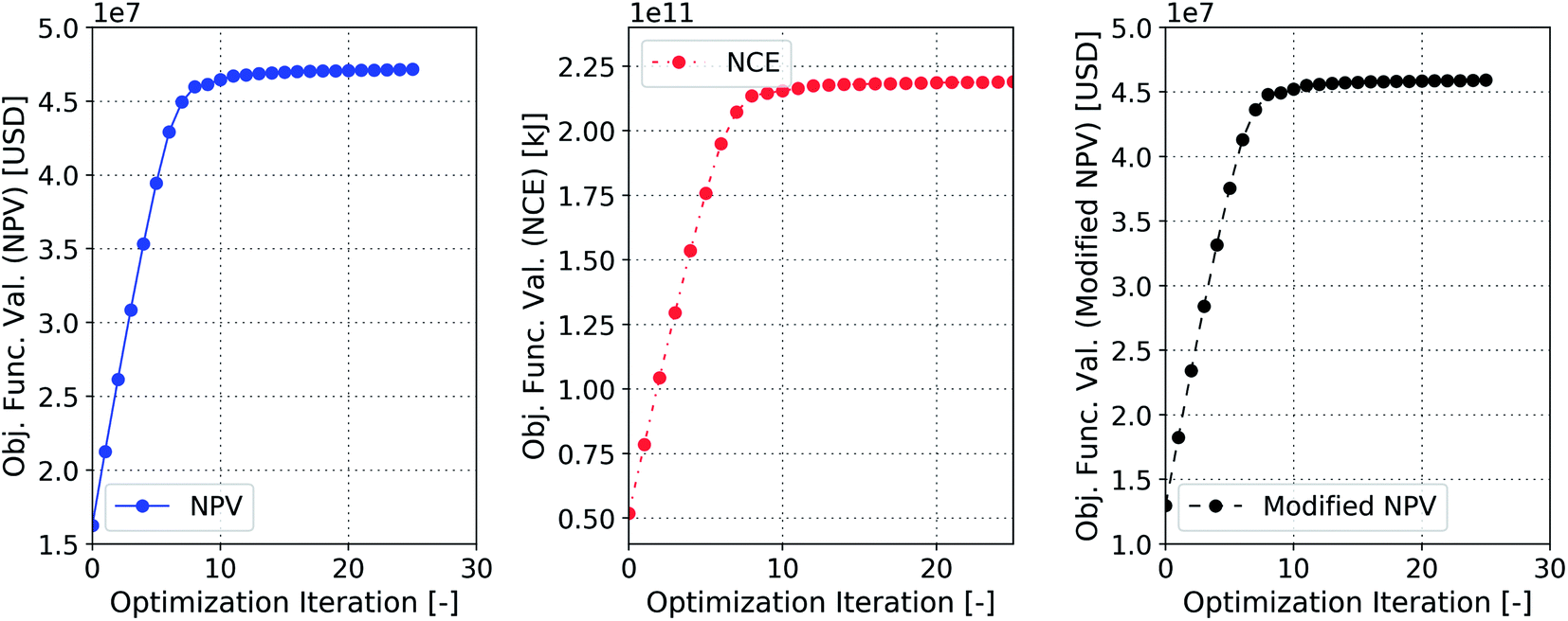
This section describes the outcome of the optimized simulations based on the different objective functions explained. Fig. 3 shows the optimization process that is aimed at maximizing the objective functions, defined by eqn (12), (13) and (15), for an initial strategy of constant injection rates of 79.5 m3 day−1. It can be seen that for all three cases after almost 10 iterations the objective function value is converged and does not change significantly. For the NPV optimization case (Fig. 3a), the value of the objective function (NPV) increases from an initial value of 16.62 MM$ to 47.16 MM$ when the optimization procedure is applied. In the NCE optimization case (Fig. 3b), the objective function value (NCE) is increased from 5.19 × 10⁴ GJ to 2.18 × 10⁵ GJ and finally in the third case (Fig. 3c), the value of the objective function (modified NPV) increases from 12.96 MM$ to 45.92 MM$, which is just ∼2.5% lower than that in the NPV optimized case.
 |
| | Fig. 3 Optimization process for the three different objective functions, defined by eqn (12), (13) and (15). | |
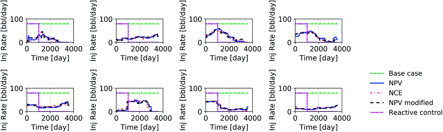
Fig. 4 shows the initial and the optimized injection rates (control variables in this study) of the eight injectors for all three optimization cases as well as the reactive-control case (shut-in at 80% water cut). The base case is constant injection rate for all injectors.
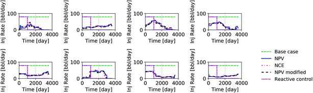 |
| | Fig. 4 Injection rates of the eight injectors during production life time for different cases. Densely dashdotdotted green line represents the base case, solid blue line indicates the NPV optimization case, dash-dotted red line represents the NCE optimization case, dashed black line represents the modified NPV optimization case and loosely dashed magenta line represents the reactive-control case. | |
When the performance of the reservoir is optimized over its lifetime, all three different objective functions result in a similar trend for the control variables; however minor discrepancies can be observed. For this geological realization, when a reactive control is applied, the injectors stop injecting at about the same time. As mentioned earlier, the producers are forced to shut down when their water cut reaches 80%. In practice many reservoirs operate at much higher water cuts (>95%).
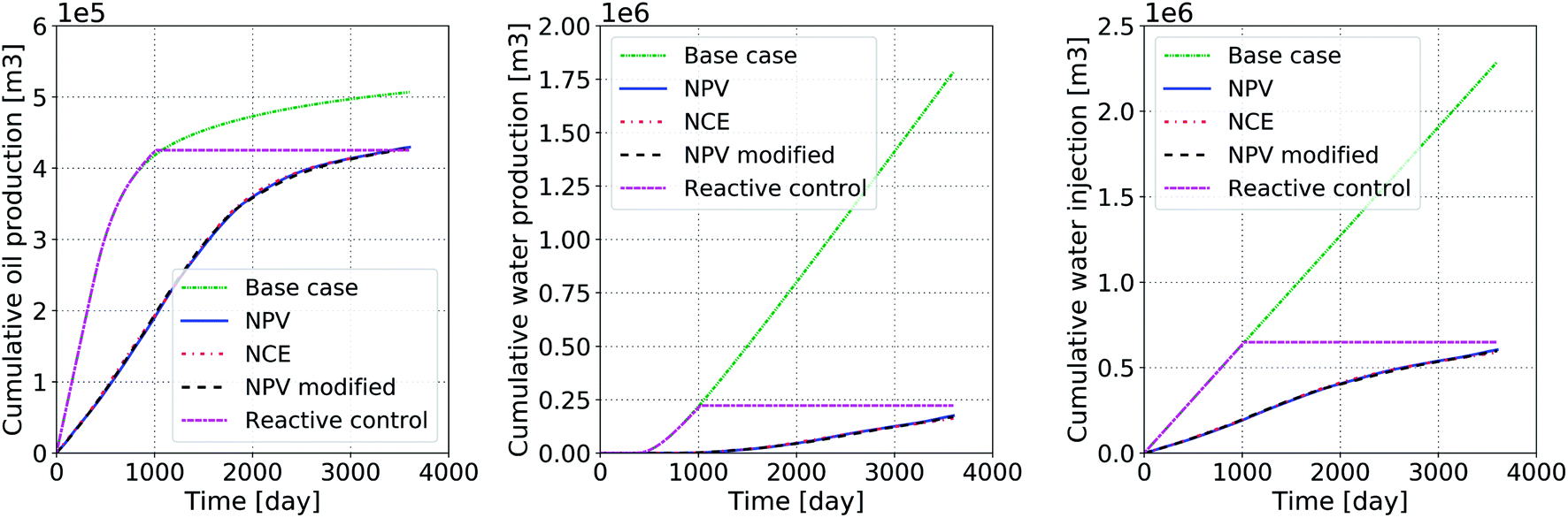
The outcome of the optimization process (production and injection rates) is shown in Fig. 5 for the different scenarios and compared to the base case with no optimization. Notably for the optimized cases, the amount of the produced oil at the end of the project is less than that in the base case. However, this is achieved by injecting considerably more water in the base case. After the optimization process, the cumulative volumes of injected and produced water are reduced by 72% and 89%, respectively. The amount of the produced oil is about 13% lower for the optimized cases (with only ∼2.5% lower NPV between the optimized cases with and without CO2 penalty). The increase of CO2 penalty from 0.05 to 0.1 $ per kg is not expected to have an impact on the final optimized value of the NPV. This implies that the values of the objective functions are maximized because of significant reduction in water production. For the reactive-control case the cumulative volumes of the injected and produced water are reduced by 67%, and 82%, respectively. The produced oil is 15% less than that in the base case.
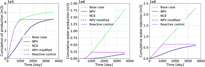 |
| | Fig. 5 Cumulative oil production, water production and water injection before (densely dashdotdotted green line) and after different optimization processes. | |
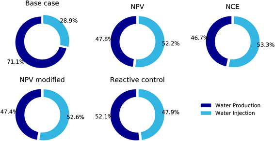
Following eqn (12) the major cost in the NPV stems from handling (pumping, treatment, etc.) of the injected and produced water. Fig. 6 shows the fractions of the total exergy and cost that is spent on the produced and injection water before and after all optimization processes as well as the reactive control case. For the geological realization and the parameters used in this paper, the major exergy waste and destruction in a water-flood project are associated with the water production. Before the optimization more than 70% of the production cost is caused by the water production; however after the optimization this fraction decreases to 50% for all optimization cases. Hence, it shows that the NPV can increase significantly by reducing the water production, leading to improvements in energy and waterflood efficiency. A similar plot can be made to quantify the contribution of each component to the total invested exergy.
 |
| | Fig. 6 Exergy or cost (investment) fractions of water injection and production for the different cases. | |
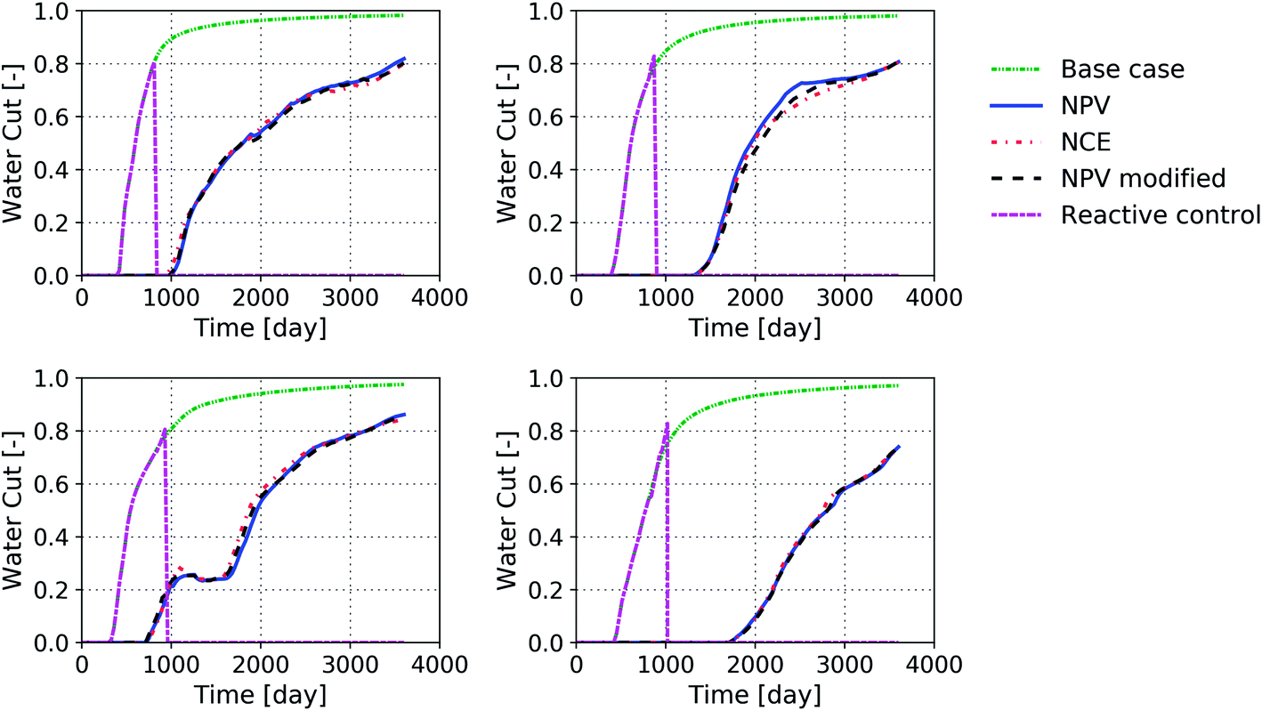
Fig. 7 and 8 present the histories of the produced oil and the water cut in the four producers for the different scenarios considered here. When no optimization is applied, oil is produced at high rates, albeit associated with injection and production of large volumes of water. In the optimized cases, the rate of oil production is smaller, which indicates that less energy (or money) should be invested to produce the oil. In the reactive-control scheme, the oil production stops once the water cut in the producers reaches the objective value. This value should be chosen such that the exergy gain from the project is maximized. This will, in many cases, lead to significant reductions in the green-house gas emissions related to the project. It can be seen from Fig. 9 that exergy loss or exergy invested to produce oil significantly increases when the water cut rises above 80%, which is why in this study the objective value was set to 80% for water cut in the reactive-control case. This value depends on the technologies used to treat the water as well as the efficiency of the pumps.
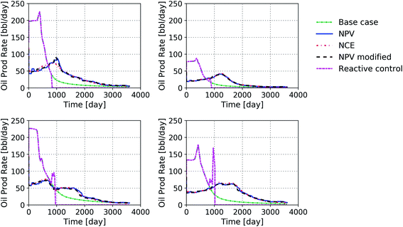 |
| | Fig. 7 History of the oil rate in the producers for the optimized and non-optimized cases. | |
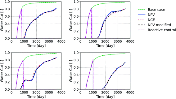 |
| | Fig. 8 History of the water cut in the producers for the optimized and non-optimized cases. | |
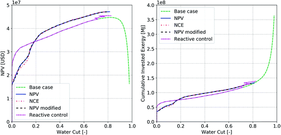 |
| | Fig. 9 (a) NPV and (b) cumulative invested exergy as a function of water cut for different cases. | |
The effect of water production on NPV and NCE behavior can be analyzed further by plotting the NPV and cumulative invested exergy as a function of water cut for different optimization cases. Fig. 9a shows the NPV value of the base case and the optimized cases as a function of water cut for the three different optimization cases and the reactive control case. Fig. 9b shows the cumulative invested exergy a function of water cut for different optimization cases. Fig. 9a reveals that as the water cut increases above 80% in the base case the NPV decreases dramatically. However, after optimization, the water cut does not increase above 80% for all cases because of the significant reduction in water production and as a result the NPV does not decrease. A similar trend is observed for the cumulative invested exergy. As the water cut increases above 80% the invested cumulative exergy starts to increase exponentially in the base case. After the optimization process (and for the reactive control case) the water cut remains below 80% for all cases and as a result the cumulative invested exergy does not increase significantly.
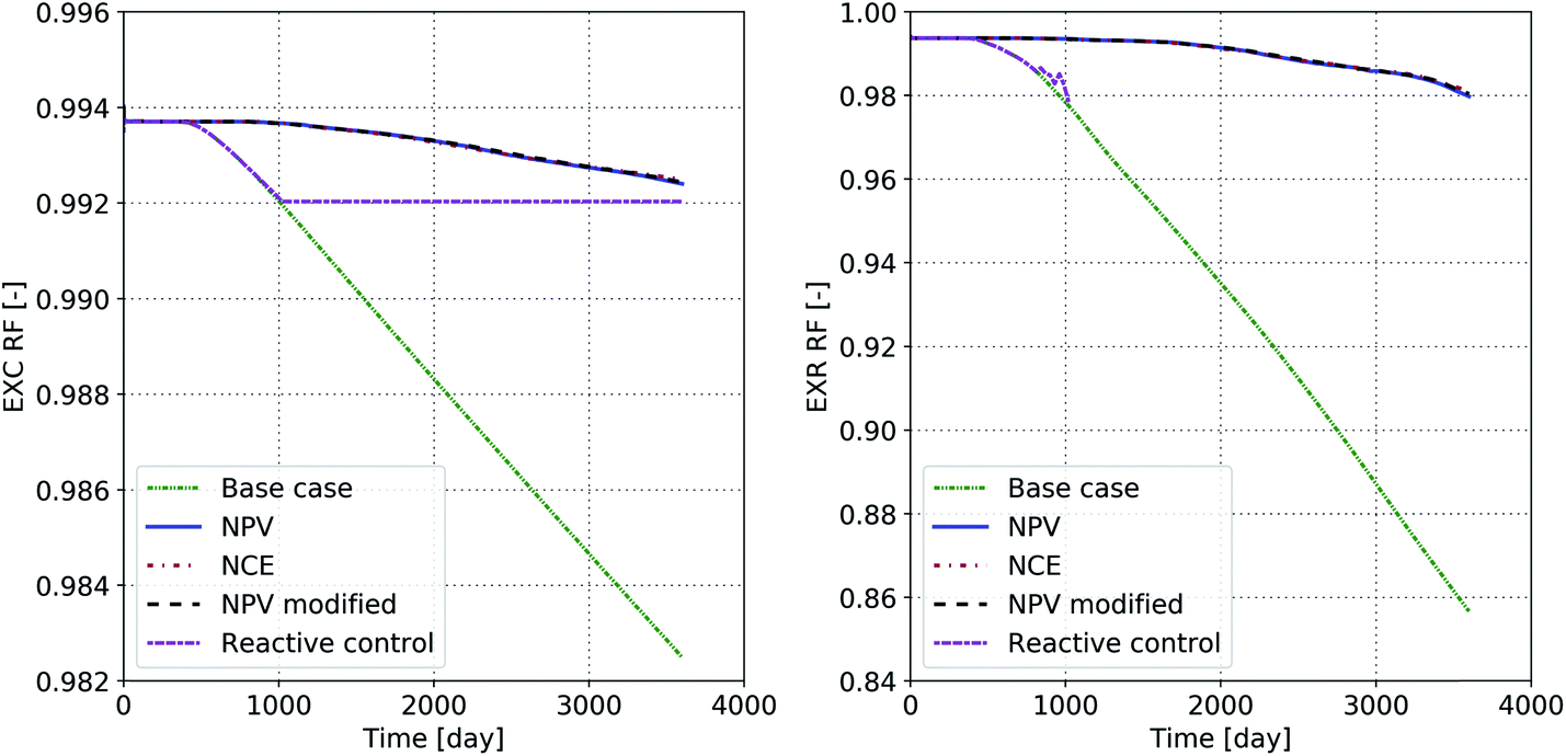
Fig. 10a shows the cumulative exergy recovery factor and Fig. 10b show the rate exergy recovery factor for the base case and the optimized cases. The rate exergy recovery factor is calculated using the rates of the injected/produced water and oil. Therefore, it does not include the large amount of oil or exergy gained during the early stages of the project. For our case, after 10 years more than 15% of the exergy gained from the oil is spent on producing it when no optimization is applied. The optimization process results in an increase of the rate exergy recovery factor to 98%, which means that only 2% of the exergy gained from oil is wasted throughout the process.
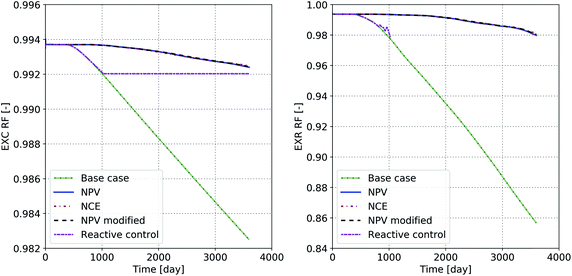 |
| | Fig. 10 (Right) Cumulative exergy recovery factor and (left) rate exergy recovery factor as a function of time. | |
Finally, Fig. 11 shows the cumulative CO2 emission for all of the cases. It can be seen that any kind of production optimization can significantly reduce the CO2 emission from water flooding projects. Water management (both on injection and production sides) plays a key role in reducing the CO2 footprint of waterflooding projects. At high water cuts (>80%) the CO2 emissions increase exponentially, as was already observed in Fig. 9b when looking at the cumulative invested exergy. This may come at the expense of smaller volumes of produced oil or lower ultimate recovery for the reservoir (see Fig. 5). This creates an opportunity for other oil production technologies, such as polymer flooding, to produce oil with a lower CO2 footprint and more economic value.
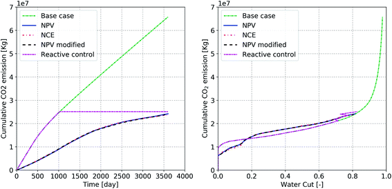 |
| | Fig. 11 Cumulative CO2 emission as a function of (right) time and (left) water cut. | |
7. Conclusion
Extraction of hydrocarbons from subsurface formations involves energy-intensive processes that could lead to significant release of CO2 into the atmosphere. The extent of CO2 emission depends on the type of oil, reservoir conditions (pressure, temperature, and heterogeneity), and more importantly the choice of the production scheme. Therefore, the decisions regarding reservoir management and/or selection of a certain recovery mechanism should consider their CO2 footprint. Here, based on the concept of thermoeconomics (or exergoeconomics), we suggest alternative objective functions that could be used in the optimization techniques for simultaneous maximization of economics and energy efficiency of the oil production projects. The suggested functions are evaluated for an oil reservoir, where water is injected to improve its recovery factor. We consider the net exergy gain during the life cycle of the water injection project. The following conclusions can be made from this study:
• Life-cycle optimization of water injection projects in terms of net present value (NPV) and net cumulative exergy (NCE) leads to consistent results.
• Managing reservoirs based on a long-term objective could lead to significant reduction in their CO2 footprint.
• For oil production by water injection, commitment to reduce CO2 emission provides an opportunity to maximize the NPV of the projects.
• The energy efficiency of the production system decreases dramatically, and its CO2 footprint increases exponentially for water cuts larger than 80%. This illustrates that water recycling in waterfloods to produce the ‘last’ barrels from the reservoir is an economically challenging and ineffective process from the CO2-emission point of view.
• Reduction of CO2 emission from oil-production projects may result in leaving some oil underground, which does not hurt the project economics. The higher remaining oil in the reservoir could be a target for a profitable and efficient polymer flood.
Conflicts of interest
There are no conflicts to declare.
References
- Global Warming of 1.5 °C, Special Report of Intergovernmental Panel on Climate Change, 2018.
- M. S. Masnadi, H. M. El-Houjeiri, D. Schunack, Y. Li, J. G. Englander, A. Badahdah, J.-C. Monfort, J. E. Anderson, T. J. Wallington and J. A. Bergerson, Global carbon intensity of crude oil production, Science, 2018, 361, 851–853 CrossRef CAS PubMed.
- A. R. Brandt, M. S. Masnadi, J. G. Englander, J. Koomey and D. Gordon, Climate-wise choices in a world of oil abundance, Environ. Res. Lett., 2018, 13, 044027 CrossRef.
- M. S. Masnadi and A. R. Brandt, Climate impacts of oil extraction increase significantly with oilfield age, Nat. Clim. Change, 2017, 7, 551 CrossRef CAS.
- M. S. Masnadi, H. M. El-Houjeiri, D. Schunack, Y. Li, S. O. Roberts, S. Przesmitzki, A. R. Brandt and M. Wang, Well-to-refinery emissions and net-energy analysis of China's crude-oil supply, Nat. Energy, 2018, 3, 220 CrossRef CAS.
- G. Cooney, M. Jamieson, J. Marriott, J. Bergerson, A. Brandt and T. J. Skone, Updating the US life cycle GHG petroleum baseline to 2014 with projections to 2040 using open-source engineering-based models, Environ. Sci. Technol., 2016, 51, 977–987 CrossRef PubMed.
- V. D. B. C. Dasireddy and B. Likozar, The role of copper oxidation state in Cu/ZnO/Al2O3 catalysts in CO2 hydrogenation and methanol productivity, Renewable Energy, 2019, 140, 452–460 CrossRef CAS.
- M. Huš, D. Kopač, N. S. Štefančič, D. L. Jurković, V. D. Dasireddy and B. Likozar, Unravelling the mechanisms of CO2 hydrogenation to methanol on Cu-based catalysts using first-principles multiscale modelling and experiments, Catal. Sci. Technol., 2017, 7, 5900–5913 RSC.
- D. L. Jurković, A. Pohar, V. D. Dasireddy and B. Likozar, Effect of Copper-based Catalyst Support on Reverse Water–Gas Shift Reaction (RWGS) Activity for CO2 Reduction, Chem. Eng. Technol., 2017, 40, 973–980 CrossRef.
-
A. Goeppert and G. S. Prakash, Beyond Oil and Gas: The Methanol Economy, Wiley VCH, 2009 Search PubMed.
- R. S. Haszeldine, Carbon capture and storage: how green can black be?, Science, 2009, 325, 1647–1652 CrossRef CAS PubMed.
- R. Farajzadeh, P. L. Zitha and J. Bruining, Enhanced mass transfer of CO2 into water: experiment and modeling, Ind. Eng. Chem. Res., 2009, 48, 6423–6431 CrossRef CAS.
- D. Y. Leung, G. Caramanna and M. M. Maroto-Valer, An overview of current status of carbon dioxide capture and storage technologies, Renewable Sustainable Energy Rev., 2014, 39, 426–443 CrossRef CAS.
- A. A. Eftekhari, H. Van Der Kooi and H. Bruining, Exergy analysis of underground coal gasification with simultaneous storage of carbon dioxide, Energy, 2012, 45, 729–745 CrossRef CAS.
- C. Kolster, M. S. Masnadi, S. Krevor, N. Mac Dowell and A. R. Brandt, CO2 enhanced oil recovery: a catalyst for gigatonne-scale carbon capture and storage deployment?, Energy Environ. Sci., 2017, 10, 2594–2608 RSC.
- R. Farajzadeh, A. A. Eftekhari, G. Dafnomilis, L. W. Lake and J. Bruining, On the sustainability of CO2 storage through CO2 Enhanced Oil Recovery, Appl. Energy Search PubMed , under review.
-
T. Anderson, Economic Analysis of Solar-Based Thermal Enhanced Oil Recovery, SPE-173466-STU, Presented at the SPE Annual Technical Conference and Exhibition, Society of Petroleum Engineers, Amsterdam, The Netherlands, 27–29 October 2014 Search PubMed.
-
D. Brouwer, G. Nævdal, J. Jansen, E. H. Vefring and C. Van Kruijsdijk, Improved Reservoir Management Through Optimal Control and Continuous Model Updating, SPE-90149-MS, Presented at SPE Annual Technical Conference and Exhibition, Society of Petroleum Engineers, Houston, Texas, 26–29 September, 2004 Search PubMed.
- M. Zandvliet, M. Handels, G. van Essen, R. Brouwer and J.-D. Jansen, Adjoint-based well-placement optimization under production constraints, SPE J., 2008, 13, 392–399 CrossRef.
-
J. Kraaijevanger, P. Egberts, J. Valstar and H. Buurman, Optimal Waterflood Design Using the Adjoint Method, SPE-105764-MS, Presented at SPE Reservoir Simulation Symposium, Society of Petroleum Engineers, Houston, Texas, U.S.A., 26–28 February, 2007 Search PubMed.
- G. van Essen, M. Zandvliet, P. Van den Hof, O. Bosgra and J.-D. Jansen, Robust waterflooding optimization of multiple geological scenarios, SPE J., 2009, 14, 202–210 CrossRef.
-
R. Fonseca, O. Leeuwenburgh, E. Della Rossa, P. M. J. Van den Hof and J.-D. Jansen, Ensemble-Based Multiobjective Optimization of On/Off Control Devices Under Geological Uncertainty, SPE-173268-PA, SPE Reservoir Eval. Eng., 2015, 18, pp. 554–563 Search PubMed.
- G. van Essen, J.-D. Jansen, R. Brouwer, S. G. Douma, M. Zandvliet, K. I. Rollett and D. Harris, Optimization of smart wells in the St. Joseph field, SPE Reserv. Eval. Eng., 2010, 13, 588–595 CrossRef CAS.
- G. Nævdal, D. R. Brouwer and J.-D. Jansen, Waterflooding using closed-loop control, Comput. Geosci., 2006, 10, 37–60 CrossRef.
- J.-D. Jansen, O. H. Bosgra and P. M. Van den Hof, Model-based control of multiphase flow in subsurface oil reservoirs, J. Process Control, 2008, 18, 846–855 CrossRef CAS.
-
J.-D. Jansen, R. Brouwer and S. G. Douma, Closed Loop Reservoir Management, SPE-119098-MS, Presented at SPE Reservoir Simulation Symposium, Society of Petroleum Engineers, The Woodlands, Texas, 2–4 February, 2009 Search PubMed.
- G. Finnveden and P. Östlund, Exergies of natural resources in life-cycle assessment and other applications, Energy, 1997, 22, 923–931 CrossRef CAS.
- R. Farajzadeh, K. Zaal, P. van Den Hoek and J. Bruining, Life-cycle assessment of water injection into hydrocarbon reservoirs using exergy concept, J. Cleaner Prod., 2019, 235, 812–821 CrossRef.
- Y.-H. Kwon, H.-Y. Kwak and S.-D. Oh, Exergoeconomic analysis of gas turbine cogeneration systems, Exergy An Int. J., 2001, 1, 31–40 CrossRef.
- M. Rosen and I. Dincer, Exergoeconomic analysis of power plants operating on various fuels, Appl. Therm. Eng., 2003, 23, 643–658 CrossRef.
- G. Tsatsaronis and J. Pisa, Exergoeconomic evaluation and optimization of energy systems—application to the CGAM problem, Energy, 1994, 19, 287–321 CrossRef.
- S. De Oliveira and M. Van Hombeeck, Exergy analysis of petroleum separation processes in offshore platforms, Energy Convers. Manage., 1997, 38, 1577–1584 CrossRef.
-
I. Dincer and M. A. Rosen, Exergy: Energy, Environment and Sustainable Development, Newnes, 2012 Search PubMed.
- T. Morosuk and G. Tsatsaronis, A new approach to the exergy analysis of absorption refrigeration machines, Energy, 2008, 33, 890–907 CrossRef CAS.
- T.-V. Nguyen, L. Pierobon, B. Elmegaard, F. Haglind, P. Breuhaus and M. Voldsund, Exergetic assessment of energy systems on North Sea oil and gas platforms, Energy, 2013, 62, 23–36 CrossRef.
-
L. Stougie, Exergy and Sustainability: Insights Into the Value of Exergy Analysis in Sustainability Assessment of Technological Systems, PhD dissertation, Delft University of Technology, 2014 Search PubMed.
- G. Tsatsaronis, Definitions and nomenclature in exergy analysis and exergoeconomics, Energy, 2007, 32, 249–253 CrossRef.
- J. Szargut, Chemical exergies of the elements, Appl. Energy, 1989, 32, 269–286 CrossRef CAS.
- Y. Liu and Y. Li, An exergy-based evaluation model for the performance of the fossil fuel life cycle, Int. J. Exergy, 2015, 17, 92–109 CrossRef CAS.
- J. Szargut and D. R. Morris, Cumulative exergy consumption and cumulative degree of perfection of chemical processes, Int. J. Energy Res., 1987, 11, 245–261 CrossRef CAS.
-
J. Mallevialle, P. E. Odendaal and M. R. Wiesner, Water Treatment Membrane Processes, American Water Works Association, 1996 Search PubMed.
-
T. J. Skone and K. Gerdes, Development of baseline data and analysis of life cycle greenhouse gas emissions of petroleum-based fuels, DOE/NETL-2009/1346, National Energy Technology Laboratory, Pittsburgh, PA, 2008 Search PubMed.
-
M. Wang, The greenhouse gases, regulated emissions, and energy use in transportation (GREET) model: Version 1.5, Cent. Transp. Res. Argonne Natl. Lab, http://https://greet.es.anl.gov/publication-h3k81jas, 1999.
- World Energy Outlook Special Report, International Energy Agency, Energy and Climate Change, 2015.
- E. Gavenas, K. E. Rosendahl and T. Skjerpen, CO2-emissions from Norwegian oil and gas extraction, Energy, 2015, 90, 1956–1966 CrossRef CAS.
-
S. Kahrobaei, G. M. van Essen, J. F. M. Van Doren, P. M. J. Van Den Hof and J. D. Jansen, in SPE Reservoir Simulation Symposium, SPE-163586-MS, Society of Petroleum Engineers, SPE, The Woodlands, Texas, USA, 18–20 February 2013, p. 12 Search PubMed.
- S. Kahrobaei, M. M. Habibabadi, G. J. P. Joosten, P. M. J. Van den Hof and J.-D. Jansen, Identifiability of Location and Magnitude of Flow Barriers in Slightly Compressible Flow, SPE J., 2016, 21, 899–908 CrossRef.
-
G. Gao and A. C. Reynolds, An Improved Implementation of the LBFGS Algorithm for Automatic History Matching, SPE-90058-MS, Presented at SPE Annual Technical Conference and Exhibition, Society of Petroleum Engineers, Houston, Texas, 26–29 September, 2004 Search PubMed.
- J. Jansen, R. Fonseca, S. Kahrobaei, M. Siraj, G. Van Essen and P. Van den Hof, The egg model-a geological ensemble for reservoir simulation, Geosci. Data J., 2014, 1, 192–195 CrossRef.
- R. Rivero, C. Rendon and L. Monroy, The Exergy of Crude Oil Mixtures and Petroleum Fractions: Calculation and Application, International Journal of Applied Thermodynamics, 1999, 2(3), 115–123 Search PubMed.
- R. Farajzadeh, Sustainable production of hydrocarbon fields guided by full-cycle exergy analysis, J. Pet. Sci. Eng., 2019, 181, 106204 CrossRef CAS.
Footnote |
| † Current address: TNO, The Netherlands. |
|
| This journal is © The Royal Society of Chemistry 2019 |
Click here to see how this site uses Cookies. View our privacy policy here. 
 Open Access Article
 This Open Access Article is licensed under a Creative Commons Attribution-Non Commercial 3.0 Unported Licence
 *ab,
S. S.
Kahrobaei†
b,
A. H.
de Zwart
a and
D. M.
Boersma
a
*ab,
S. S.
Kahrobaei†
b,
A. H.
de Zwart
a and
D. M.
Boersma
a