Lindqvist polyoxometalates as electrolytes in p-type dye sensitized solar cells†
Tijmen M. A.
Bakker
 ,
Simon
Mathew
 and
Joost N. H.
Reek
 *
*
Van t' Hoff Institute for Molecular Sciences, University of Amsterdam, Amsterdam, 1098XH, Netherlands. E-mail: J.n.h.reek@uva.nl
First published on 21st November 2018
Abstract
The development of new redox couples provides a clear strategy to improve power conversion efficiency (PCE) in p-type dye-sensitized solar cells (p-DSSCs) through enabling improvements in open-circuit voltage (VOC). In this work we report the use of molybdenum and tungsten containing Lindqvist polyoxometalates (POMs), [TBA]2Mo6O19 and [TBA]2W6O19, as an alternative to the traditionally used I−/I3− redox mediator in p-DSSCs. POM electrolytes are cheap and easy to synthesize, air stable and transparent, making them suitable for tandem solar cell applications. Electrolytes were evaluated using a simple testing device to benchmark the respective devices. Up to a 5-fold increase in VOC was observed for p-DSSCs employing electrolytes with POMs upon comparison with traditionally used I3−/I−, while short-circuit photocurrents with the same order of magnitude were observed under identical dilute conditions.
Introduction
With an ever increasing energy demand and the prospect of climate change as a consequence of greenhouse gas emission, alternatives to fossil fuels are needed. Solar energy has the most potential for providing this energy in a sustainable fashion.1 Dye-sensitized solar cells (DSSCs) are considered as a promising low-cost alternative to traditional crystalline silicon solar cells.2 Furthermore, they can be made from sustainable materials and can absorb diffuse light, making them suitable for small scale appliances.3,4n-Type DSSCs based on mesoporous TiO2 have achieved an efficiency of 11.9% with traditional iodide electrolytes, with greater power conversion efficiencies (PCEs) made possible through the use of alternative redox couples, enabling PCE improvements through increases in open-circuit voltage (VOC) without sacrificing short-circuit photocurrent (JSC).5–8 Complementary improvements in p-type DSSCs (p-DSSC), based on mesoporous NiO semiconductors, aim to enable the fabrication of highly efficient tandem DSSC devices. However, p-DSSCs exhibit much lower PCEs than n-type DSSCs.9–12
Besides engineering the mesoporous semiconductor and dye of the p-DSSC, the development of the redox mediator within the electrolyte of the p-DSSC provides a clear pathway to device optimization, as evidenced by several groups using cobalt pyridyl complexes,13,28 disulfides/thiolates,14 cobalt diaminoethane complexes15 and iron acetylacetonate complexes.16 Traditionally used I3−/I− couples have been scrutinized due to their ambiguous mechanism as an electrolyte and parasitic absorption of visible light. The absorption of visible light by the I3−/I− couple removes photons utilizable by the dye, reducing JSC, while the radical I2˙− formed upon visible light excitation, recombines with a photogenerated hole at the semiconductor–electrolyte interface,17 compromising the VOC of the device. Importantly, devices based on I3−/I− electrolytes suffer from low VOC, as their redox potential is not energetically matched in an optimal fashion with the optoelectronic properties of the dye. The redox potential of the I3−/I− electrolyte also limits its solar fuel applications, to drive for example CO2-reduction catalysts.
Bach et al. demonstrated an elegant solution to improving VOC in p-DSSCs by employing [Co(en)3]3+/2+ and [Fe(acac)3]0/1− redox mediators that exhibit higher redox potentials than I3−/I− couples, enabled by appropriate matching of dye electronics, leading to higher PCEs.13–16 It is important to note that the increase in redox potential is solely beneficial for p-type DSSCs and not for tandem cells. The cobalt and iron based electrolytes are however unstable in air and therefore have to be prepared under inert conditions, complicating device fabrication. Also, the cobalt and iron based electrolytes compete for visible light absorption with the dyes, making them less suitable for tandem solar cell applications.
Polyoxometalates (POMs) are well-known anionic metal oxide clusters that can host several heteroatoms.18 POMs are widely used because of their electrochemical properties. Recent applications included water oxidation catalysts, as components in redox flow batteries, lithium ion batteries and super capacitors.19–22 POMs have also been used as co-adsorbents on NiO surfaces in p-type DSSCs, which showed a decreased recombination rate and increased VOC.23 To our knowledge, POMs have not been employed as redox mediators in p-DSSCs.
In this work we report the use of Lindqvist polyoxometalates (POMs) as electrolytes for p-type DSSCs. Lindqvist POMs have a molecular formula M6O192− and spherical shape. As we are particularly interested in the development of p-type DSSCs with higher VOC for the realization of solar fuel devices, a simple testing device was constructed to enable rapid optimization (Fig. 6).
Results and discussion
The Lindqvist POMs used in this work are [TBA]2Mo6O19 and [TBA]2W6O19. The structure of a typical Lindqvist POM is depicted in Fig. 1.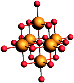 | ||
| Fig. 1 Typical Lindqvist M6O192− polyoxometalate with the metal atoms depicted in orange and the oxygen atoms depicted in red. | ||
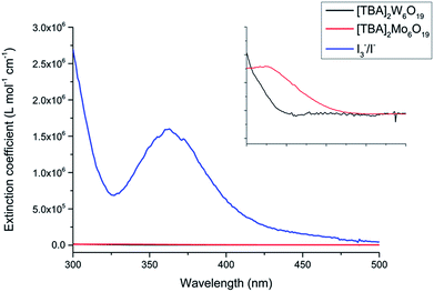
The POMs were synthesized via two simple procedures as previously described by Fournier and Wang et al., with the characterization of the POM structure achieved by single crystal X-ray diffraction.24 The POMs have been made from cheap starting materials, employing abundant elements coupled with air stability, making them amenable to scale-up. The [TBA]2Mo6O19 and [TBA]2W6O19 POMs demonstrated respective solubilities of 21 g L−1 and 67 g L−1 in acetonitrile, limiting their application in DSSCs. The acetonitrile solution of [TBA]2Mo6O19 afforded a faintly yellow solution and [TBA]2W6O19 yielded a clear solution. As shown in Fig. 2, the molar absorption coefficients of both POMs are over 100 times lower than that of the traditional I3−/I− electrolyte.
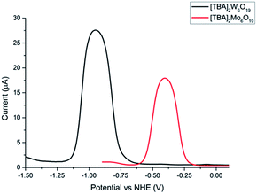
A combination of cyclic voltammetry and differential pulse voltammetry was employed to determine the redox potential, reversibility and diffusion coefficient of both POMs. Fig. 3 shows the differential pulse voltammogram of both POMs, which exhibit respective redox potentials of −0.40 V and −0.90 V (vs. NHE) for [TBA]2Mo6O19 and [TBA]2W6O19. The experiments were performed under aerobic conditions, showing the air stability of the POMs. The broad peak separation in the cyclic voltammetry experiments and the bell shaped curve in the differential pulse voltammogram experiments can be explained by the fact that no supporting electrolyte was used and the experiments were done in acetonitrile (see the ESI†).
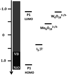
Given that the redox potential of I3−/I−, [Co(en)3]3+/2+ and [Fe(Acac)3]0/1− is reported to be +0.32 V, −0.03 V and −0.20 V vs. NHE respectively,16 the [TBA]2W6O19 POM demonstrates the lowest redox potential to our knowledge. The low redox potential of [TBA]2W6O19 should translate into an elevated VOC in the p-DSSC device, making the POMs an excellent candidate as a redox mediator. Fig. 4 shows an energy level diagram of the components in the p-type DSSCs used in this work. The LUMO of the P1 dye has been reported to be around −0.93 V vs. NHE.11,25 This means that there is 0.03 V available for electron transfer from the dye to the redox mediator in the case of [TBA]2W6O19. Although this should be enough energy to regenerate the [TBA]2W6O19 POM, a low JSC can be expected as the driving force is very small, reducing the rate of this electron transfer process. In the case of [TBA]2Mo6O19 there is 0.53 V of driving force available, which should afford lower VOC values than those of the [TBA]2W6O19 POM, but higher JSC values.
Cyclic voltammetry presented in Fig. 5 demonstrates that both POMs are electrochemically reversible. The scan-rate dependent measurements provide information on the diffusion constants of the different POMs.16 Using the Randles–Sevcik equation, the electrochemical data show that [TBA]2Mo6O19 and [TBA]2W6O19 have a diffusion coefficient of 2.02 (±0.35) × 10−7 cm2 s−1 and 1.08 (±0.09) × 10−7 cm2 s−1 respectively. Earlier studies with the [Fe(acac)3]0/1− electrolyte revealed that this species demonstrates a diffusion coefficient of 7.1 (±0.78) × 10−6 cm2 s−1.16 It was also reported that the JSC was limited by diffusion, a well-known phenomenon observed when employing redox mediators with greater size.16 Since the POMs in this work feature lower diffusion coefficients, it is likely that the JSC of the corresponding p-DSSCs will experience diffusion limitations.
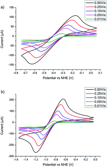 | ||
| Fig. 5 Scan rate dependent cyclic voltammetry with a glassy carbon working electrode, a platinum counter electrode and a Ag/AgCl reference electrode of (a) [TBA]2Mo6O19 and (b) [TBA]2Mo6O19. Conversion of potential vs. Ag/AgCl to the NHE is given in the ESI.† | ||
We designed and fabricated a simple device to specifically measure the VOC in a simple and expedient manner. The device is made from a screen-printed NiO photocathode (1.57 cm2) on FTO glass, subsequently sensitized with the frequently used P1 dye.25–27 As depicted in Fig. 6, the counter electrode was made from platinum coated FTO. In the device the two electrodes are separated by a 1 cm distance by a Teflon container, featuring a large opening at the top to facilitate the introduction and removal of electrolyte solutions, and washing of the system. The Teflon container has a volume of 3 mL of electrolyte solution. It is expected that the increased distance between the electrodes will amplify diffusion limitations in the system, leading to lower JSC, but it allows the benchmarking of the VOC of various devices in an expeditious manner.29
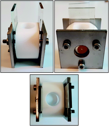 | ||
| Fig. 6 Simple testing device used in this work to benchmark the open current voltage. Design schematics of the device are shown in the ESI.† | ||
Table 1 summarizes the photovoltaic parameters obtained from the measurement of the J–V properties of the DSSCs. The POM electrolytes are compared with the I3−/I− electrolyte at a reduced concentration (0.01 M as opposed to 1.0 M) due to the limited solubility of the POM materials in MeCN. Interestingly, devices based on the POM electrolytes (entries 1 & 2) show a dramatic increase in VOC compared the I3−/I− couple (entry 3), corresponding clearly to the differences in redox potentials measured from electrochemical characterization. Also, the elevated VOC of [TBA]2W6O19 compared to [TBA]2Mo6O19 is consistent with the slightly higher oxidation potential of [TBA]2W6O19. Comparing the two POM-electrolyte devices, the lower JSC of the [TBA]2W6O19 device (entry 1) can be explained by either the smaller driving force for the reduction of [TBA]2W6O19 by the photoreduced dye compared to [TBA]2Mo6O19 or the greater diffusion coefficient. Given that the JSC values of all devices have the same order of magnitude when low concentration redox mediators are utilized, the POM materials are promising candidates as electrolytes for p-type DSSCs. Wu et al. showed the impact of the electrolyte recombination resistance on the fill factor.30 It is likely that this is also the cause of the low fill factor in this system. The results in Table 1 also show the effect of increasing the concentration of the electrolyte (entries 3 and 4), when using the I3−/I− couple. Both the VOC and the short-circuit current increase when the concentration is higher. Since the solubility of the POMs in acetonitrile is low, similar experiments with these electrolytes are not possible. Clearly, more soluble analogues are required for practical applications.
| Entry | Electrolyte | V OC (mV) | J SC (mA cm−2) | FF |
|---|---|---|---|---|
| a 0.5 M of LiTFSI was present as the supporting electrolyte. The data shown are the average and the standard deviation of at least 5 different experiments. | ||||
| 1 | 0.01 M [TBA]2Mo6O19a | 423 ± 28 | 0.021 ± 0.002 | 0.13 ± 0.02 |
| 2 | 0.01 M [TBA]2W6O19a | 541 ± 34 | 0.010 ± 0.001 | 0.11 ± 0.02 |
| 3 | 0.01 M I3−/I−a | 100 ± 5 | 0.032 ± 0.003 | 0.23 ± 0.01 |
| 4 | 1.0 M I3−/I− | 144 ± 14 | 0.107 ± 0.013 | 0.31 ± 0.02 |
| 5 | 1.0 M I3−/I− (literature)26 | 106 | 3.010 | 0.37 |
| 6 | Co(tbpy)3 (literature)27 | 80 | 0.26 | 0.26 |
The effectiveness of the simple test cell is clear when comparing our results with those reported in the literature. The VOC obtained for the test cell are similar to those reported in the literature (entries 4 and 5), and only the JSC is lower as a result of the large distance between the electrodes. Given the fact that it is really easy to change the electrolyte solution, the test cell is very suitable for benchmarking VOC.
Conclusions
We have shown that polyoxometalates can be used as electrolytes in p-type dye sensitized solar cells. The POMs presented in this work are easy to prepare based on cheap starting materials. A unique feature of these POMs as electrolytes is that they are transparent and can therefore be suitable for tandem solar cell applications. An increased VOC is not directly beneficial to tandem solar cell applications, but may be useful for pure p-type solar cells. The POMs are also air stable, allowing for easy preparation of the electrolyte and the DSSC. We also report a simple testing setup that allows us to benchmark the open current potential for different devices thereby facilitating the optimization of electrolyte solutions.In line with what we expected on the basis of the redox potentials of the POM materials, measured by electrochemistry, we found a 4 to 5-fold increase in VOC when applying these POM electrolytes in comparison to the devices with the traditional I3−/I− couple. We plan to exploit these voltages in proton and CO2 reduction for solar fuel applications. The high VOC is sufficient to drive proton reduction catalysis and CO2 reduction catalysis. The JSC have the same order of magnitude under the same conditions. Currently, the low solubility of the POMs is the main hampering factor for increasing the short-circuit current of these cells. Increasing the solubility of these POM materials should therefore be the main focus point when improving the efficiency of these cells. After solubility issues are fixed, traditional DSSCs can be made in order to achieve record efficiencies.
Conflicts of interest
There are no conflicts to declare.Acknowledgements
The authors would like to thank Merck GmbH and the Dutch National Science Foundation (NWO) for funding. The authors would like to give special thanks to Dr J. I. Van der Vlugt for performing the SXRD measurements, Dr R. Detz for fruitful discussions and L. van den Burg for the synthesis of the P1 dye.References
- M. Grätzel, Nature, 2001, 414, 338–344 CrossRef.
- B. O'Regan and M. Grätzel, Nature, 1991, 353, 737–740 CrossRef.
- A. Hagfeldt, G. Boschloo, L. Sun, L. Kloo and H. Petterson, Chem. Rev., 2014, 110, 4474–4490 Search PubMed.
- F. Bella, S. Galliano, M. Falco, G. Viscardi, C. Barolo, M. Grätzel and C. Gerbaldi, Green Chem., 2017, 19, 1043–1051 RSC.
- R. Komiya in Technical Digest, 21st International Photovoltaic Science and Engineering Conference, 2011, 2 C-5O-08 Search PubMed.
- K. Kakiage, Y. Aoyama, T. Yano, K. Oya, J. Fujisawa and M. Hanaya, Chem. Commun., 2015, 51, 15894–15897 RSC.
- Y. Cao, Y. Liu, S. Zakeeruddin, A. Hagfeldt and M. Grätzel, Joule, 2018, 6, 1108–1117 CrossRef.
- Q. Yu, Y. Wang, Z. Yi, N. Zu, J. Zhang, M. Zhang and P. Wang, ACS Nano, 2010, 4, 6032–6038 CrossRef CAS PubMed.
- Y. Pellegrin, L. Le Pleux, E. Blart, A. Renaud, B. Chavillon, N. Szuwarski, M. Boujita, L. Cariob, S. Jobic, D. Jacquemina and F. Odobel, J. Photochem. Photobiol., A, 2011, 219, 235–242 CrossRef CAS.
- M. Yu, G. Natu, Z. Ji and Y. Wu, J. Phys. Chem. Lett., 2012, 3, 1074–1078 CrossRef CAS PubMed.
- P. Qin, J. Wiberg, E. A. Gibson, M. Linder, L. Li, T. Brinck, A. Hagfeldt, B. Albinsson and L. Sun, J. Phys. Chem. C, 2010, 114, 4738–4747 CrossRef CAS.
- A. Nattestad, A. J. Mozer, M. K. R. Fischer, Y. Cheng, A. Mishra, P. Bäuerle and U. Bach, Nat. Mater., 2010, 9, 31–35 CrossRef CAS PubMed.
- E. A. Gibson, A. L. Smeigh, L. Le Pleux, L. Hammarström, F. Odobel, G. Boschloo and A. Hagfeldt, J. Phys. Chem. C, 2011, 155, 9772–9779 CrossRef.
- X. Xu, B. Zhang, J. Cui, D. Xiong, Y. Shen, W. Chen, L. Sun, Y. Chengad and M. Wang, Nanoscale, 2013, 5, 7963–7969 RSC.
- S. Powar, T. Daeneke, M. T. Ma, D. Fu, N. W. Duffy, G. Götz, M. Weidelener, A. Mishra, P. Bäuerle, L. Spiccia and U. Bach, Angew. Chem., 2013, 125, 630–633 CrossRef.
- I. R. Perera, T. Daeneke, S. Makuta, Z. Yu, Y. Tachibana, A. Mishra, P. Bäuerle, C. A. Ohlin, U. Bach and L. Spiccia, Angew. Chem., Int. Ed., 2015, 54, 3758–3762 CrossRef CAS PubMed.
- F. Odobel, Y. Pellegrin, E. A. Gibson, A. Hagfeldt, A. L. Smeigh and L. Hammarström, Coord. Chem. Rev., 2012, 256, 2414–2423 CrossRef CAS.
- T. Ueda, ChemElectroChem, 2018, 5, 823–838 CrossRef CAS.
- Y. V. Geletii, B. Botar, P. Kçgerler, D. A. Hillesheim, D. G. Musaev and C. L. Hill, Angew. Chem., Int. Ed., 2008, 47, 3896–3899 CrossRef CAS PubMed.
- H. D. Pratt III and T. M. Anderson, Dalton Trans., 2013, 42, 15650–15655 RSC.
- J. J. Chen, M. D. Symes, S. C. Fan, M. S. Zheng, H. N. Miras, Q. F. Dong and L. Cronin, Adv. Mater., 2015, 27, 4649–4654 CrossRef CAS PubMed.
- P. Gómez-Romero, M. Chojak, K. Cuentas-Gallegos, J. A. Asensio, P. J. Kulesza, N. Casañ-Pastor and M. Lira-Cantffl, Electrochem. Commun., 2003, 5, 149–153 CrossRef.
- H. El Moll, F. A. Black, C. J. Wood, A. Al-Yasari, M. Reddy Marri, I. V. Sazanovich, E. A. Gibson and J. Fielden, Phys. Chem. Chem. Phys., 2017, 19, 18831–18835 RSC.
- R.-C. Wang and M. Fournier, Inorg. Synth., 1990, 27, 85–96 Search PubMed.
- P. Qin, H. Zhu, T. Edvinsson, G. Boschloo, A. Hagfeldt and L. Sun, J. Am. Chem. Soc., 2008, 130, 8570–8571 CrossRef CAS.
- T. Daeneke, A. J. Mozer, Y. Uemura, S. Makuta, M. Fekete, Y. Tachibana, N. Koumura, U. Bach and L. Spiccia, J. Am. Chem. Soc., 2012, 134, 16925–16928 CrossRef CAS PubMed.
- N. Li, E. A. Gibson, P. Qin, G. Boschloo, M. Gorlov, A. Hagfeldt and L. Sun, Adv. Mater., 2010, 22, 1759–1762 CrossRef PubMed.
- E. A. Gibson, A. L. Smeigh, L. Le Pleux, J. Fortage, G. Boschloo, E. Blart, Y. Pellegrin, F. Odobel, A. Hagfeldt and L. Hammarström, Angew. Chem., 2009, 48, 4402–4405 CrossRef CAS PubMed.
- A. Yella, S. Mathew, S. Aghazada, P. Comte, M. Grätzel and M. Nazeeruddin, J. Mater. Chem. C, 2017, 5, 2833 RSC.
- Z. Huang, G. Natu, Z. Ji, M. He, M. Yu and Y. Wu, J. Phys. Chem. C, 2012, 116, 26239–26246 CrossRef CAS.
Footnote |
| † Electronic supplementary information (ESI) available: Synthesis details, materials and methods. See DOI: 10.1039/c8se00495a |
| This journal is © The Royal Society of Chemistry 2019 |

