Rational design W-doped Co-ZIF-9 based Co3S4 composite photocatalyst for efficient visible-light-driven photocatalytic H2 evolution
Haiyu
Wang
ab and
Zhiliang
jin
 *ab
*ab
aSchool of Chemistry and Chemical Engineering, North Minzu University, Yinchuan, 750021, P. R. China. E-mail: zl-jin@nun.edu.cn
bKey Laboratory of Chemical Engineering and Technology, State Ethnic Affairs Commission, North Minzu University, Yinchuan 750021, P. R. China
First published on 15th October 2018
Abstract
Herein, a novel W doped Co3S4 composite photocatalyst was successfully prepared by MOF (metal organic framework), Co-ZIF-9, as a nanoscaled template via a hydrothermal treatment. Efficient heteroatom doping emerged a large number of joints in Co3S4–WSX, providing multitudinous active sites for hydrogen catalysis. Moreover, due to these unmatched structural and compositional features, the optimized Co3S4–WSX hybrid without introducing any noble metal cocatalysts in the catalytic system also displayed a brilliant performance for hydrogen evolution and prominent stability under long-term visible light irradiation. In particular, the sample of Co3S4–WSX(0.6)), the amount of hydrogen evolution in the five-hour continuous light could reach up to 428.3 μmol, which was increased by 38 times compared with Co-ZIF-9. In addition, some necessary characterization such as XRD, FTIR, SEM, TEM, XPS, BET, UV-vis diffuse spectroscopy, photoelectrochemistry and PL etc. were further examed to support related results and put forward the possible reaction mechanism.
1. Introduction
As a type of crystalline nanoporous materials, metal–organic frameworks (MOFs) are composed of metal centers and organic linkers. It has attracted much more attention not only owing to their distinct structural topologies and chemical tunabilities but also their multitudinous beneficial characteristics and applications.1–8 Furthermore, it could be used in catalytic hydrogen production as an effective method to reduce over-reliance on non-renewable fossil fuel combustion, because H2 as an intermediate medium for storing and transporting energy could be more likely achieved pollution-free and more efficient energy exploitation.9–15 In the past ten years, a lot of prospective new green energy conversion technologies such as fuel cells, water splitting (OER or ORR), and CO2RR have been widely probed and developed.16–21 As a matter of fact, at the design and synthesis of advanced materials for water splitting has been spend great costs in recent years. However, because of the materials that could catalyze these energy conversion reactions in an efficient, durable, environmentally friendly, and low-cost way are still absent, necessary efforts also should be devoted.22–27Since meaningful work were further opened up by Yaghi and co-workers, which showed that MOFs are a very promising material in gas sorption, selective separation, catalysis and sensing. The advantage of being exceptionally prominent is that MOFs could be combined with a series of transition metal ions, functionalized imidazolate linkers, and varying topologies. This meaningful design feature brings about a rapid growth of this novel class of crystals in synthetic materials chemistry.28–30 Among them, the most prominent is 2D metal–organic framework (MOF) nanosheets, and it could achieve the control of structure and functionality over extended length scales by coordination bonding, thus highly ordered metal–organic framework (MOF) nanosheets could be obtained. Additionally, metal–organic framework (MOF) nanosheets are equally important for basic structure–property research and technological development, if a better exfoliation methods could be optimized, and the exfoliation of 3D layered MOFs into their 2D constituents will be more easier.31–33
Another better strategy for producing functional materials based on MOF is the combination of MOF materials with other materials such as silica, polystyrene, magnetic particles and precious metal particles. In recent years, a new class of materials has been developed that in some ways bridges the gap between MOFs and zeolites, namely, zeolitic imidazolate frameworks (ZIFs). Zeolitic imidazolate frameworks (ZIFs), a family of metal azolate frameworks, composed of tetrahedrally coordinated metal centers interconnected by imidazolate linkers, are a class of MOFs that inherit their structural and physicochemical features from both MOFs and zeolites,34–38 therefore, it is widely used in many fields. Research has demonstrated that the high surface area and pore structure of ZIFs could constrain the fast diffusion of metal ions during pyrolysis, leading to a large electrochemical surface area and uniform distribution of metal ions with high doping levels, thus further contributing to enhanced ORR and HER electrocatalytic activities.39
Many zeolite topologies have been reported to date by using different imidazolide linkers, such as LTA, POZ and MOZ.40–42 The study found that Co-ZIF-9 possesses an open-framework structure using a sodalite topology with hexagonal symmetry, it forms a tetrahedral CoN4 building block by the coordination of cobalt atoms with the nitrogen atom at the 1,3 position on the benzimidazole ester linkage, and this unit is further combined into a Co-ZIF-9.43 It is therefore desirable to find a series of photochemically stable light non-precious metals harvesters to couple with Co-ZIF-9 to construct a stable semiconductor-redox system for promoting the H2 reduction reaction under visible light. In this work, we selected a novel step ammonia-assisted route to prepare Co-ZIF-9 and Co3S4, W element were successfully introduced in situ via hydrothermal treatment. The photocatalytic performance of Co3S4–WSX photocatalysts was obviously better than that of the untreated Co-ZIF-9 photocatalyst, owing to enhanced visible-light absorption and improved charge carrier separation under visible light. In addition, dye-sensitization of the semiconductor as one of the great strategies using visible light, it is necessary to investigate photocatalytic systems that effectively work under visible light region. So we also studied the photocatalytic activity of the catalyst in the dye sensitization system, and the reaction system of the photocatalyst has been optimized and a detailed mechanism for promoting activity was also posed.
2. Experimental section
2.1. Preparation of catalysts
All reagents were of analytical grade and could be used without further purification.2.2. Preparation of Co-ZIF-9 photocatalysts
Benzimidazole (H-PhIM) (0.118 g) and a solid mixture of cobalt nitrate hexahydrate (0.14 g) were dissolved with stirring into 25 mL ultrapure water, then ammonia water (5 mL) was added after 5 min, and then the resulting solution was continued stirring for 30 minutes. After the solution was left to stand for 6 hours, the resulting sample was washed with ultrapure water and filtered, and transferred to a sample catalyst holding tube for storage.2.3. Preparation of Co3S4–WSX photocatalysts
The prepared Co-ZIF-9 photocatalyst (0.15 g) was added in a beaker, then added 30 mL ultrapure water was dispersed 10 min to form a suspension, 0.329 g sodium tungstate (1 mmol) and 0.15 g thioacetamide were respectively added, after the formation of a homogeneous solution, 9 mL ammonia water was added, continue stirring for 30 minutes. There, the mixed suspension is transferred to a polytetrafluoroethylene reactor for 12 h at 180 °C and naturally cooled to room temperature at the end of the reaction. The precipitate was with deionized water for removed the un-reacted precursor and evaporated to dryness, the obtained products were denoted as Co3S4–WSX(1.0), different amounts were denoted as Co3S4–WSX(0.2), Co3S4–WSX(0.4), Co3S4–WSX(0.6), Co3S4–WSX(0.8), respectively.2.4. Characterization
FT-IR spectra were examined on Thermo Nicolet Avatar 380 FT-IR spectrometer. X-ray diffraction (XRD) crystalline structure analysis using Cu Kα radiation (tube current 40 mA, tube voltage 40 keV). Ultraviolet and visible spectrophotometer (UV-vis) diffuse reflectance spectra was carried out a UV-2550 (Shimadzu) spectrometer. The SEM of all samples were performed by field emission scouldning electron microscopy (JSM-6701F JEOL) at an accelerating voltage of 5.0 kV. High-resolution transmission electron microscopy (TEM) characterization was using an FEI TePCNai TF20 high-resolution transmission electron microscopy with the accelerated voltage of 300 kV. The element composition was detected by X-ray photoelectron spectroscope (XPS, ESCALAB 250Xi). The nitrogen adsorption–desorption isotherms of samples were measured at 77 K with an ASAP 2020M instrument and analyzed by the Brunauer–Emmett–Teller (BET) equation. Photoluminescence data (PL) were obtained by a FLUOROMAX-4 spectrophotometer in a mild environment.2.5. Photocatalytic hydrogen production tests
Photocatalytic hydrogen production tests were conducted in a quartz reaction flask (62 cm3) which was irradiated by a 5 W white light lamp under magnetic stirring condition (PCX50A Discover 5 W). The specific operation is that 10 mg of photocatalyst powder and 20 mg dye Eosin Y (EY) powder were suspended in 30 mL 15% (v/v) triethanolamine (TEOA) aqueous solution. In order to clear away the air in the reaction flask, the homogeneous solution was purged with bubbling N2 for 15 min. The amount of hydrogen evolution was measured using gas chromatography (Tianmei GC7900, TCD, 13X column, N2 as a carrier). All glassware was rigorously cleaned and carefully rinsed with distilled water prior to use.2.6. Photoelectrochemical measurements
3. Results and discussion
In this study, we used FTIR technology as a diagnostic tool for detecting sample changes. The detail of the test information could be obtained from 2.4. Characterization. Comparison of Co-ZIF-9 and Co3S4–WSX photocatalysts patterns revealed many differences. As you could see from Fig. 1, the bands from 400 cm−1 to −650 cm−1 could correspond to the Co N bonds in Co-ZIF-9. The shape peak at about 745 cm−1 could be assigned to C–H out-of-plane bending vibration,44 this could also prove the formation of Co-ZIF-9. But when it is converted to Co3S4, the correlation characteristic peak intensity decreased gradually. May be the rupture of C–H, the peak was visibly disappeared with increasing W element usage. The sharp peaks at 1461 cm−1 could be assigned to the ring vibrations, and the absorption at 1606 cm−1 could be assigned to the CN stretching mode, these two points could fully prove the formation of Co-ZIF-9. In addition, the peaks range from 1125 cm−1 to 1140 cm−1 were caused by the vulcouldization of Co-ZIF-9.45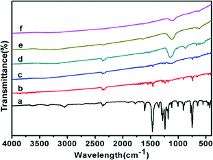 | ||
| Fig. 1 FTIR patterns of Co-ZIF-9 and Co3S4–WSX photocatalysts, (a–f) represent Co-ZIF-9, Co3S4–WSX(0.2), Co3S4–WSX(0.4), Co3S4–WSX(0.6), Co3S4–WSX(0.8), Co3S4–WSX(1.0), respectively. | ||
The chemical structure of Co-ZIF-9, Co3S4–WSX(0.2), Co3S4–WSX(0.4), Co3S4–WSX(0.6), Co3S4–WSX(0.8) and Co3S4–WSX(1.0) photocatalysts were also compared by XRD techniques. As shown in Fig. 2a, the Co-ZIF-9 pattern shows several distinct peaks. The first peak with a peak of 8.98° could be allocated to the (100) plane of it, and the peaks at 21.5° and 27.5° exhibited two diffraction signals. By comparison with Co3S4–WSX photocatalysts, it was shown that after the addition of S and W elements, the phase of Co-ZIF-9 shown some clear changes. The peaks at 16.102°, 26.667°, 31.361°, 38.049°, 47.279°, 50.225° and 55.006° corresponded to the (111) plane, (220) plane, (311) plane, (400) plane, (422) plane, (511) plane and (440) of linnaeite (PDF#42-1448), it may have been formed during the catalyst synthesis, which agreed with the XPS results.46 It is regrettable that the characteristic diffraction peaks corresponding to crystalline WSX have not been detected. The first reason may be the low amount of W element, another reason may be the high dispersion of WSX and the relatively low diffraction intensity, it could indicate that the loaded WSX were amorphous.
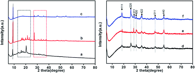 | ||
| Fig. 2 XRD patterns of Co-ZIF-9 and Co3S4–WSX photocatalysts, (a–f) represent Co-ZIF-9, Co3S4–WSX(0.2), Co3S4–WSX(0.4), Co3S4–WSX(0.6), Co3S4–WSX(0.8) and Co3S4–WSX(1.0) photocatalysts. | ||
In order to study the light absorption capacity of Co-ZIF-9, Co3S4–WSX(0.2), Co3S4–WSX(0.6) and Co3S4–WSX(1.0) composite photocatalysts, UV-vis spectroscopy characterization was further examed, the relevant results were shown in Fig. 3. The UV-vis absorption spectra of Co-ZIF-9 photocatalysts shown some absorption bands in the UV region, which could be allocated to intra ligand n → π* and π → π* transitions. In addition, due to the spin-allowed d–d transition, and this process could occur at a lower energy level so that Co-ZIF-9 displayed a wide absorption band at 600 nm–650 nm.47 The light absorption properties of all modified samples showed a regular change. It was clearly shown that the coupling of WSX had effect on the intrinsic optical properties of Co-ZIF-9. This result could also prove WSX evenly presented on the surface of ZIF-9 rather than being doped into it. After the introduction of the W element, the Co3S4–WSX composite catalysts exhibited additional absorption at longer wavelengths, this could be used in part to excite Co3S4–WSX photocatalysts to promote the photocatalytic evolution of H2.
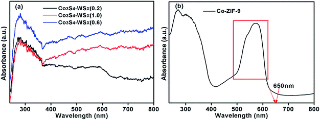 | ||
| Fig. 3 (a) The UV-vis diffuse reflection spectra of Co3S4–WSX(0.2), Co3S4–WSX(0.6) and Co3S4–WSX(1.0). (b) The UV-vis diffuse reflection spectra of Co-ZIF-9. | ||
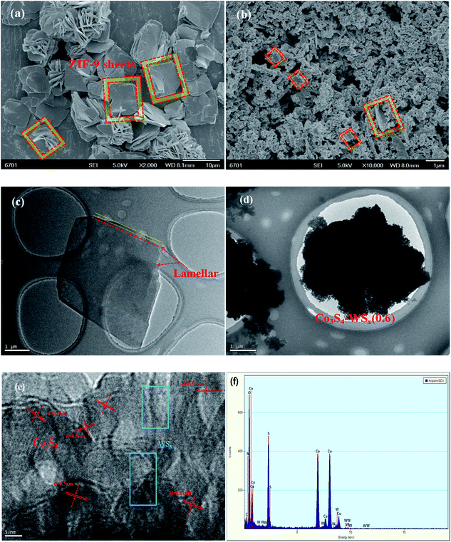
The prepared Co-ZIF-9 and Co3S4–WSX photocatalysts were characterized by SEM and TEM analysis, and the basic structure of the composite catalyst and the important role of W element in enhancing photocatalytic hydrogen evolution were further explored. Fig. 4 a shows the SEM image of the Co-ZIF-9 sheets, it is clear that about 10 μm square sheets are arranged together, some are reunited, and the surface is smooth, the corrugations of some wrinkles in the sample indicate that the resulted Co-ZIF-9 was not a single layer. Fig. 4b shown an SEM image of Co3S4–WSX(0.6) photocatalyst, showing that Co3S4–WSX were successfully prepared. Furthermore, the TEM image of Co3S4–WSX(0.6) (Fig. 4d) also reveals that the Co3S4–WSX evenly distributed. This result indicated that Co-ZIF-9 has successfully transformed into Co3S4–WSX, and the structure has changed little. We could see from Fig. 4e the lattice spacing of 0.50 nm and 0.11 nm can be assigned to the (111) plane and the (440) plane of Co3S4, respectively. Tungsten sulfide did not exhibit significant lattice fringes due to its low crystallinity. We could also see from Fig. 4f the elements C, N, O, Co, S, and W were very clearly present in the composite catalyst.
We used X-ray photoelectron spectroscopy (XPS) to investigate the surface chemical states of Co3S4–WSX(0.6) photocatalysts (Fig. 5). The full scould spectrum corroborates the existence of S, Co and W elements in the sample, with no obvious extra impurities detected, which in agreement with the EDX results. In the S 2p spectra (Fig. 5b), the binding energy of the peaks at 169.0 eV and 170.2 eV could be fitted by SO42− species, which maybe originate from the WSX synthesis and the other two peaks at 162.5 eV and 161.6 eV were attributed to the S 2p1/2 and S 2p3/2 orbitals of divalent sulfur ions, respectively.48Fig. 5c shown the narrow spectrum of Co 2p contained in the catalyst, we could see that the spectrum was deconvolved into two rotating orbital double peaks and two vibrating satellite peaks. The first doublet at 778.5 eV and 793.6 eV were attributed to Co 2p3/2 and the second were 781.9 eV and 798.6 eV for Co 2p1/2.49 The narrow spectrum of the W element is not obvious, but this does not affect the relevant results, because EDX could also confirm its existence. The W 4f peaks at 31.3 eV and 31.5 eV could be attributed to the W 4f7/2 and W 4f5/2, the binding energy gap between the two is 2.2 eV, which is consistent with the standard W narrow spectrum, and the binding energy at 37.1 eV is attributed to W 5p3.50
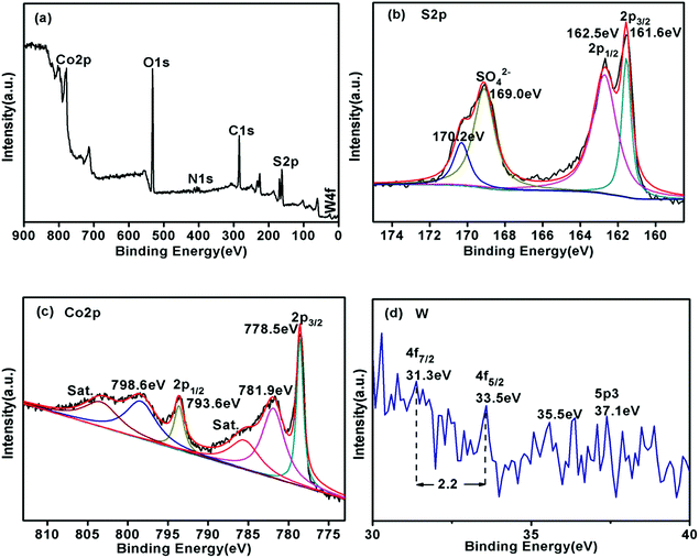 | ||
| Fig. 5 X-ray photoelectron spectroscopy (XPS) patterns of Co3S4–WSX(0.6) composite photocatalysts. (a) Survey spectrum, (b) S 2p, (c) Co 2p, (d) W. | ||
As shown in Fig. 6, in order to study the effect of the loading of W on the internal microstructure of Co3S4–WSX(0.6) composite photocatalyst, we tested the specific surface area (SBET), pore size distribution and pore structure of the relevant samples by N2 adsorption–desorption measurements at 77 K. The nitrogen adsorption–desorption isotherm (Fig. 6a) of Co-ZIF-9 and Co3S4–WSX(0.6) composite photocatalysts are identified as typical type IV with type H3 hysteresis loop, which is characteristic of mesoporous materials. In addition, an adsorption hysteresis loop appeared in the middle section of this isotherm, which was corresponded to a system in which the porous adsorbent exhibited capillary condensation. However, this H3 type hysteresis loop did not exhibit adsorption saturation in the higher relative pressure region, which was indicated that the sample to be tested may be composed of flake granular material. As shown in Table 1, the obtained Brunauer–Emmett–Teller (BET) specific surface area (SBET)of Co-ZIF-9 was only 7.3746 m2 g−1, which was smaller than that of Co3S4–WSX(0.2) (7.8235 m2 g−1), Co3S4–WSX(0.4) (8.5428 m2 g−1), Co3S4–WSX(0.6) (10.9294 m2 g−1), Co3S4–WSX(0.8) (8.2354 m2 g−1), Co3S4–WSX(1.0) (8.4526 m2 g−1). The single-point total volume of pores was 0.025145 cm3 g−1, 0.049453 cm3 g−1, 0.055158 cm3 g−1, 0.064460 cm3 g−1,0.065251 cm3 g−1, and 0.065985 cm3 g−1, respectively. Based on the above discussion, we could draw the following conclusions that improved the specific surface area and grown total pore volume strongly support the fact that the major modify role of W element.
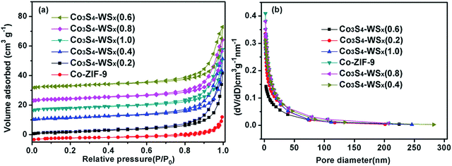 | ||
| Fig. 6 (a) BET adsorption–desorption isotherms of catalysts, (b) the corresponding pore size distributions. | ||
| Sample | BET surface area (m2 g−1) | Mean pore diameter (nm) | Pore volume (cm3 g−1) |
|---|---|---|---|
| Co-ZIF-9 | 7.3746 | 6.5506 | 0.025145 |
| Co3S4–WSX(0.2) | 7.8235 | 7.0152 | 0.049453 |
| Co3S4–WSX(0.4) | 8.5428 | 8.9256 | 0.055158 |
| Co3S4–WSX(0.6) | 10.9294 | 13.7756 | 0.064460 |
| Co3S4–WSX(0.8) | 8.2354 | 13.8256 | 0.065251 |
| Co3S4–WSX(1.0) | 8.4526 | 13.8298 | 0.065985 |
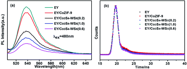
For the sake of discussing the electron transfer and excited state interactions between EY and Co3S4–WSX composite photocatalysts, the photoluminescence (PL) experiments were further performed. As shown in Fig. 7a, EY solution excited at 480 nm exhibits an extensive emission peak at 540 nm because of its conjugated xanthene structure and strong recombination of photogenerated charges and holes.51 As Co-ZIF-9 and Co3S4–WSX composite photocatalysts were introduced into the EY solution, different level fluorescence quenching was observed; with the introduce of Co3S4–WSX(0.6) composite photocatalysts this signal progressively dropped to lowest. The results showed that the recombination rate of electron–hole pairs was reduced, ensuring efficient charge transfer from excited EY to Co3S4–WSX(0.6) composite photocatalyst under visible light irradiation.52
Moreover, the fluorescence emission decays of the EY presence of Co-ZIF-9 and Co3S4–WSX composite photocatalysts are measured, the relevant time-resolved photoluminescence (TRPL) was fitted by a tri-exponential decay model, the equation as follows:
 | (1) |
Fig. 7b shown the results of the fitted, revealing that Co3S4–WSX composite photocatalysts possess more efficient electron–hole pairs separation efficiency compare with Co-ZIF-9; we further calculated the average lifetimes according to eqn (2) is listed in Table 2:
 | (2) |
| Samples | A 1 (%) | τ 1 (s) | A 2 (%) | τ 2 (s) | A 3 (%) | τ 3 (s) | 〈τ〉 (s) | χ 2 |
|---|---|---|---|---|---|---|---|---|
| EY | 89.73 | 1.67 × 10⁻¹⁰ | 10.27 | 4.00 × 10⁻⁹ | — | — | 1.85 × 10⁻¹⁰ | 1.572 |
| EY/Co-ZIF-9 | 10.72 | 3.73 × 10⁻⁹ | 26.77 | 9.79 × 10⁻⁸ | 62.51 | 5.51 × 10⁻¹¹ | 8.79 × 10⁻¹¹ | 1.361 |
| EY/Co3S4–WSX(0.2) | 11.02 | 3.77 × 10⁻⁹ | 23.05 | 9.81 × 10⁻⁸ | 65.93 | 1.26 × 10⁻¹⁰ | 1.89 × 10⁻¹⁰ | 1.301 |
| EY/Co3S4–WSX(0.6) | 0.77 | 3.83 × 10⁻⁹ | 2.07 | 9.90 × 10⁻⁸ | 97.16 | 1.02 × 10⁻¹¹ | 1.05 × 10⁻¹¹ | 1.270 |
| EY/Co3S4–WSX(1.0) | 9.75 | 3.59 × 10⁻⁹ | 12.06 | 8.02 × 10⁻⁸ | 78.19 | 1.51 × 10⁻¹⁰ | 1.92 × 10⁻¹⁰ | 1.305 |
It could be clearly seen from Table 2 that great changes have taken place in the average lifetime of all samples, the average lifetime of EY, EY/Co-ZIF-9, EY/Co3S4–WSX(0.2), EY/Co3S4–WSX(0.6), and EY/Co3S4–WSX(1.0) were 1.85 × 10⁻¹⁰, 8.79 × 10⁻¹¹, 1.89 × 10⁻¹⁰, 1.05 × 10⁻¹¹ and 1.92 × 10⁻¹⁰, respectively. The average life dropped to a minimum when Co3S4–WSX(0.6) composite photocatalyst is introduced, it could be probably attributed to the appropriate cocatalyst addition, which offers a track for photo-generated charge transfer and further improves photocatalytic activity.
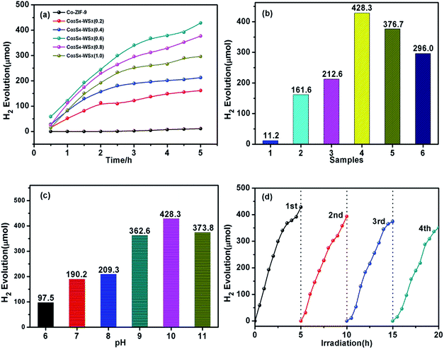
We tested the hydrogen production activity of the prepared catalyst in an aqueous solution containing 15% (v/v) triethanolamine (TEOA), related results were shown in Fig. 8a and b. It could be seen from the figure that even after EY sensitization, the hydrogen evolution activity of Co-ZIF-9 was much lower than that of the modified sample Co3S4–WSX. This phenomenon fully highlights the main role of WSX as an effective carrier for transfer electrons. In particularly, the sample with the best ratio of the load was Co3S4–WSX(0.6) composite photocatalyst, which was shown a higher promoting effect on the photocatalytic hydrogen production process. Specifically, it could be expressed that under the continuous visible light irradiation for 5 hours, the maximum H2 production amount reached 428.3 μmol, which was achieved a surprising effect. There was a clear contrast that the further increase in WSX content reduced the evolutionary activity of H2, which could be explained by the fact that although these samples showed stronger visible light absorption due to doping of WSX, excessive doping leads to WSX polymerization. The formation of the body, which could prevent the composite material from absorbing more incident light, thereby reducing the photocatalytic activity.
We could conclude that the incorporation of WSX could effectively improve the photocatalytic activity of Co3S4 for H2 production, and the effect of the pH value of the system on the hydrogen evolution activity needed further to study. As shown in Fig. 8c, due to TEOA as sacrificial agents will be fully protonated under weakly acidic conditions, thereby weakening their ability to supply electrons, a lower hydrogen production activity was exhibited. On the other hand, in this unfavorable reaction system, the lifetime and utilization of the excited state EY molecules were low, thus reducing the photocatalytic activity. In the case where the alkalinity was too strong, the driving force of H+ reduction was lowered due to a sharp drop in the amount of H+ in the solution, which was suppressed the generation of hydrogen. These results indicated that the EY dye could be efficiently adsorbed on the Co3S4–WSX composite photocatalyst at pH 10 and conducted efficient electron transport, but it was easily quenched by a reduction in TEOA at pH 11.
In addition, we also carried out long-term stability experiments on Co3S4–WSX(0.6) composite photocatalyst. The total time of photocatalytic reaction was controlled at 20 h, and intermittent replacement gas was performed every 5 h, the test results were shown in Fig. 8d. It could be seen from the figure that the photocatalytic H2 production activity of Co3S4–WSX(0.6) composite photocatalyst remained fairly stable under long-term illumination. The activity of the catalyst decreased slightly after four cycles, which was negligible because the photosensitizer EY had a certain degree of photocorrosion under prolonged illumination.
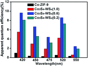
To further illustrate the H2 evolution activity of the EY/Co-ZIF-9 and EY/Co3S4–WSX system, the apparent quantum efficiencies (AQEs) for H2 evolution from EY/Co-ZIF-9 and EY/Co3S4–WSX systems are compared over a wide visible light range of 420–550 nm, as shown in Fig. 9. It could be seen that with the wavelength increasing, AQEs are gradually decreasing. At a wavelength of 420 nm, the EY/Co3S4–WSX system shown the highest AQEs (9.64%), the reason for this phenomenon is that photons at 420 nm have higher energy. Furthermore, another high AQE was obtained at 520 nm, which corresponded to the highest absorption wavelength of EY.
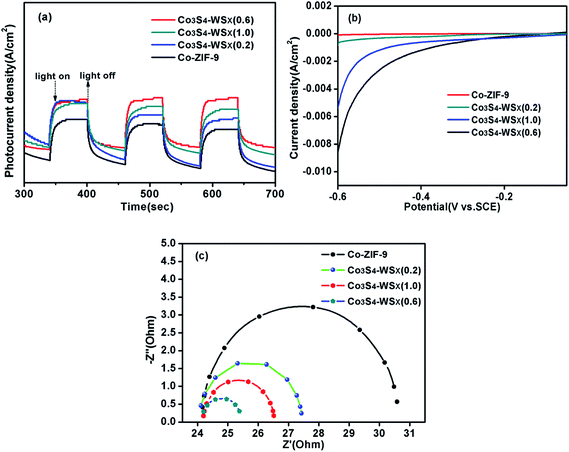
We explored the effect of the ratio of the bond between Co3S4 and WSX on charge transfer by means of photoelectrochemical technology. Transient photocurrent response was first examed for the Co-ZIF-9, Co3S4–WSX(0.2), Co3S4–WSX(0.6) and Co3S4–WSX(1.0) composite photocatalysts in 0.2 M Na2SO4 aqueous solution. The corresponding visible light response could be seen during the switching cycle of the illumination, the Co-ZIF-9 photocatalyst is featureless due to its extremely inefficient charge separation. In contrast, with increasing co-catalyst loading amount a visible increase is showing up, in particular to Co3S4–WSX(0.6) composite photocatalyst. The reason for this could be understood as an excessive amount of WSX forming aggregates having a larger diameter on the Co-ZIF-9 plate as the amount of the catalyst is increased, so that an effective reactive site was continuously reduced to be detrimental to hydrogen production.
In addition, the linear sweep voltammetry (LSV) of all samples further highlighted the importance of co-catalyst for hydrogen production, as shown in Fig. 10b. The introduction of W had a significouldt effect on the cathode current density during cathodic polarization. The cathodic current densities of Co-ZIF-9, Co3S4–WSX(0.2), Co3S4–WSX(0.6) and Co3S4–WSX(1.0) composite photocatalysts are constantly increasing, it is clearly demonstrated that loading of a suitable amount of cocatalyst could greatly promote the electron transfer process and further increase the catalyst activity of the photocatalyst.
Last but not least, the kinetics of interface electron transfer could also be obtained by electrochemical impedance spectroscopy. The EIS Nyquist plots of Co-ZIF-9, Co3S4–WSX(0.2), Co3S4–WSX(0.6) and Co3S4–WSX(1.0) composite photocatalysts were shown in Fig. 10c. With the addition of different co-catalysts, ever-reduced semicircle could be observed; when the Co3S4–WSX(0.6) composite photocatalyst is added, the semicircle reached its minimum, indicating that suitable co-catalyst results in a lower charge transport resistance of charges, and a higher separation efficiency of charges and holes, thereby facilitating photocatalytic hydrogen evolution.
Base on the above analysis, the proposed mechanism over Co3S4–WSX was further put forward. As shown in Scheme 1, the possible mechanism proposed was to explain the process of visible light photocatalytic hydrogen production in the EY-sensitized Co3S4–WSX photocatalytic system in an aqueous solution of triethanolamine and the optimization of its related properties. From our perspectives, the Co-ZIF-9 photocatalyst did not provide sufficient electrons for long-term water reduction, because a large portion of those small amounts of excited electrons were prefer to recombine with holes at the limited active sites it provided, leading to a lower H2 evolution activity. After introducing W on Co3S4–WSX, this cocatalyst captures photogenerated electrons quickly, effectively preventing the recombination of electrons and holes. In addition, since it provided a rich exposed active site, the H+ contained in the solution could be largely reduced to produce H2. Significantly, properly introduced W could maximize their efficiency, which greatly enhanced the photocatalytic H2 evolution activity of Co3S4–WSX. After using EY as a photosensitizer, it could adsorb to the surface of the obtained composite catalyst, and after the photon was absorbed in EY, the original state is changed to form a singlet excited state EY1*. However, the EY1* in the singlet excited state is unstable, and it could reach to the triplet excited state EY3* with lower energy level through the intersystem transition. When triethanolamine was present, it could reduce the EY3* that was in the triplet excited state to EY1*, while it itself was converted to an oxidizing donor for the consumption of holes. Photogenerated electrons could be transferred to Co3S4via EY1* and then transferred to a supported WSX promoter for water reduction to produce hydrogen.
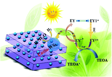 | ||
| Scheme 1 The proposed EY-sensitized photocatalytic mechanism in TEOA aqueous solution of hydrogen evolution by water splitting under visible light irradiation(λ ≦ 420 nm). | ||
4. Conclusions
In summary, we have demonstrated that low-crystalline WSX could be controllably loaded on Co3S4 materials through a simple one-step hydrothermal process, and the effective sensitization of organic dye EY to Co3S4 composite catalyst makes it an efficient cocatalyst to catalyze the evolution of H2 under visible light irradiation. Even the Co3S4–WSX(0.2) photocatalyst, which has the lowest W doping level, was increased by up to 14 times, proving that WSX as co-catalyst could effectively transfer electrons, which could directly or indirectly enhance the light response of the established EY sensitization system to achieve efficient hydrogen production. In addition, supported by some necessary characterization (e.g. PL and electrochemistry), we also proved that nanoparticles could enhance the photocatalytic activity of the catalyst to some extent via the speculated mechanism.Author contributions
Haiyu Wang conceived and designed the experiments; Zhiliang Jin contributed reagents/materials and analysis tools; Haiyu Wang wrote the paper.Conflicts of interest
The authors declare that they have no competing interests.Acknowledgements
This work was financially supported by the Chinese National Natural Science Foundation (21862002 and 41663012), the Graduate Student Innovation Project of North Minzu University (YCX18078), The Ningxia Low-grade Resource High Value Utilization and Environmental Chemical Integration Technology Innovation Team Project, North Minzu University and the New Technology and System for Clean Energy Catalytic Production, Major Scientific Project of North Minzu University (ZDZX201803).References
- U. Mueller, M. Schubert, F. Teich, H. Puetter, K. Schierle-Arndt and J. Pastre, J. Mater. Chem., 2006, 16, 626–636 RSC.
- H. Furukawa, N. Ko, Y. B. Go, N. Aratani, S. B. Choi, E. Choi, A. Ö. Yazaydin, R. Q. Snurr, M. O'Keeffe, J. Kim and O. M. Yaghi, Science, 2010, 329, 424–428 CrossRef CAS PubMed.
- H. Xu, R. Chen, Q. Sun, W. Lai, Q. Su, W. Huang and X. Liu, Chem. Soc. Rev., 2014, 43, 3259–3302 RSC.
- A. M. Bohnsack, I. A. Ibarra, V. I. Bakhmutov, V. M. Lynch and S. M. Humphrey, J. Am. Chem. Soc., 2013, 135, 16038–16041 CrossRef CAS PubMed.
- T. K. Maji, R. Matsuda and S. Kitagawa, Nat. Mater., 2007, 6, 142–148 CrossRef CAS PubMed.
- K. K. Tanabe and S. M. Cohen, Angew. Chem., Int. Ed., 2009, 48, 7424–7427 CrossRef CAS PubMed.
- S. T. Meek, J. A. Greathouse and M. D. Allendorf, Adv. Mater., 2011, 23, 249–267 CrossRef CAS PubMed.
- B. Chen, L. Wang, Y. Xiao, F. R. Fronczek, M. Xue, Y. Cui and G. Qian, Angew. Chem., Int. Ed., 2009, 48, 500–503 CrossRef CAS PubMed.
- W. Wang, X. Xu, W. Zhou and Z. Shao, Adv. Sci., 2017, 4, 1600371 CrossRef PubMed.
- M. Rakowski Dubois and D. L. Dubois, Acc. Chem. Res., 2009, 42, 1974–1982 CrossRef CAS PubMed.
- J. Low, B. Cheng and J. Yu, Appl. Surf. Sci., 2017, 392, 658–686 CrossRef CAS.
- X. Li, X. Hao, A. Abudula and G. Guan, J. Mater. Chem. A, 2016, 4, 11973–12000 RSC.
- F. Bonaccorso, L. Colombo, G. Yu, M. Stoller, V. Tozzini, A. C. Ferrari, R. S. Ruoff and V. Pellegrini, Science, 2015, 347, 1246501 CrossRef PubMed.
- Y. Zhu, P. Guo, C. Y. Zheng and S. Z. Qiao, Acc. Chem. Res., 2017, 50, 915–923 CrossRef CAS PubMed.
- I. Roger, M. A. Shipman and M. D. Symes, Nat. Rev. Chem., 2017, 1, 0003 CrossRef CAS.
- G. Zhao, X. Huang and X. Wang, J. Mater. Chem. A, 2017, 5, 21625–21649 RSC.
- H. H. Ou, P. J. Yang, L. H. Lin, M. Anpo and X. C. Wang, Angew. Chem., Int. Ed., 2017, 56, 10905–10910 CrossRef CAS PubMed.
- J. W. Huang, Y. Zhang and Y. Ding, ACS Catal., 2017, 7, 1841–1845 CrossRef CAS.
- W. Y. Zhang, Y. X. Li and S. Q. Peng, ACS Appl. Mater. Interfaces, 2016, 8, 15187–15195 CrossRef CAS PubMed.
- X. Q. Hao, Y. C. Wang, J. Zhou, Z. W. Cui, Y. Wang and Z. G. Zou, Appl. Catal., B, 2018, 221, 302–311 CrossRef CAS.
- C. C. Wang, Y. Guo, Y. Yang, S. Chu, C. K. Zhou, Y. Wang and Z. G. Zou, ACS Appl. Mater. Interfaces, 2014, 6, 4321–4328 CrossRef CAS PubMed.
- C. M. Ding, J. Y. Shi, Z. L. Wang and C. Li, ACS Catal., 2017, 7, 675–688 CrossRef CAS.
- W. Zhang, W. Lai and R. Cao, Chem. Rev., 2017, 117, 3717–3797 CrossRef CAS PubMed.
- W. Xia, A. Mahmood, Z. Liang, R. Zou and S. Guo, Angew. Chem., Int. Ed., 2016, 55(18), 2650–2676 CrossRef CAS PubMed.
- T. Reier, H. N. Nong, D. Teschner, R. Schlögl and P. Strasser, Adv. Energy Mater., 2017, 7, 1601275 CrossRef.
- J. Wang, F. Xu, H. Jin, Y. Chen and Y. Wang, Adv. Mater., 2017, 29, 1605838 CrossRef PubMed.
- S. Sui, X. Wang, X. Zhou, Y. Su, S. Riffat and C. J. Liu, J. Mater. Chem. A, 2017, 5, 1808–1825 RSC.
- R. Banerjee, H. Furukawa, D. Britt, C. Knobler, M. O'Keeffe and O. M. Yaghi, J. Am. Chem. Soc., 2009, 131, 3875–3877 CrossRef CAS PubMed.
- H. L. Jiang, B. Liu, T. Akita, M. Haruta, H. Sakurai and Q. Xu, J. Am. Chem. Soc., 2009, 131, 11302–11303 CrossRef CAS PubMed.
- H. Bux, A. Feldhoff, J. Cravillon, M. Wiebcke, Y. S. Li and J. Caro, Chem. Mater., 2011, 23, 2262–2269 CrossRef CAS.
- M. G. Campbell, S. F. Liu, T. M. Swager and M. Dincă, J. Am. Chem. Soc., 2015, 137, 13780–13783 CrossRef CAS PubMed.
- Y. Peng, Y. Li, Y. Ban, H. Jin, W. Jiao, X. Liu and W. Yang, Science, 2014, 346, 1356–1359 CrossRef CAS PubMed.
- R. Makiura, S. Motoyama, Y. Umemura, H. Yamanaka, O. Sakata and H. Kitagawa, Nat. Mater., 2010, 9, 565–571 CrossRef CAS PubMed.
- M. Zhao, Q. Lu, Q. Ma and H. Zhang, Small Methods, 2017, 1, 1600030 CrossRef.
- O. Karagiaridi, W. Bury, A. A. Sarjeant, C. L. Stern, O. K. Farha and J. T. Hupp, Chem. Sci., 2012, 3, 3256–3260 RSC.
- B. Wang, A. P. Côté, H. Furukawa, M. O'Keeffe and O. M. Yaghi, Nature, 2008, 453, 207–211 CrossRef CAS PubMed.
- K. S. Park, Z. Ni, A. P. Cote, J. Y. Choi, R. Huang, F. J. Uribe-Romo, H. K. Chae, M. O'Keeffe and O. M. Yaghi, Proc. Natl. Acad. Sci. U. S. A., 2006, 103, 10186–10191 CrossRef CAS PubMed.
- J. P. Zhang, Y. Zhang, J. Lin and X. Chen, Chem. Rev., 2012, 112, 1001–1033 CrossRef CAS PubMed.
- H. Hayashi, A. P. Côté, H. Furukawa, M. O'Keeffe and O. M. Yaghi, Nat. Mater., 2007, 6, 501–506 CrossRef CAS PubMed.
- I. A. Baburin, S. Leoni and G. Seifert, J. Phys. Chem. B, 2008, 112, 9437–9443 CrossRef CAS PubMed.
- M. Kuang, Q. H. Wang, P. Han and G. F. Zheng, Adv. Energy Mater., 2017, 7, 1700193 CrossRef.
- A. Phan, C. J. Doonan, F. J. Uribe-Romo, C. B. Knobler, M. O'Keeffe and O. M. Yaghi, Acc. Chem. Res., 2010, 43, 58–67 CrossRef CAS PubMed.
- B. Wang, A. P. Cote, H. Furukawa, M. O'Keeffe and O. M. Yaghi, Nature, 2008, 453, 207–211 CrossRef CAS PubMed.
- L. T. L. Nguyen, K. K. A. H. Le, X. Truong and N. T. Sphan, Catal. Sci. Technol., 2012, 2, 521–528 RSC.
- J. Low, J. Yu, M. Jaroniec, S. Wageh and A. A. Al-Ghamdi, Adv. Mater., 2017, 29, 1601694 CrossRef PubMed.
- L. Poul, N. Jouini and F. Fivet, Chem. Mater., 2000, 12, 3123–3132 CrossRef CAS.
- A. B. P. Lever, Coord. Chem. Rev., 1968, 3, 119–140 CrossRef CAS.
- X. Q. Hao, Z. L. Jin, H. Yang, G. X. Lu and Y. P. Bi, Appl. Catal., B, 2017, 210, 45–56 CrossRef CAS.
- Y. R. Liu, W. H. Hu, X. Li, B. Dong, X. Shang, G. Q. Han, Y. M. Chai, Y. Q. Liu and C. G. Liu, Appl. Surf. Sci., 2016, 384, 51–57 CrossRef CAS.
- X. Zheng, J. Guo, Y. Shi, F. Xiong, W. Zhang, T. Ma and C. Li, Chem. Commun., 2013, 49, 9645–9647 RSC.
- Q. Y. Li, L. Chen and G. X. Lu, J. Phys. Chem. C, 2007, 111, 11494–11499 CrossRef CAS.
- S. De, S. Das and A. Girigoswami, Spectrochim. Acta, Part A, 2005, 61, 1821–1833 CrossRef PubMed.
| This journal is © The Royal Society of Chemistry 2019 |

