
 Open Access Article
 This Open Access Article is licensed under a Creative Commons Attribution-Non Commercial 3.0 Unported Licence
A hybrid blue perovskite@metal–organic gel (MOG) nanocomposite: simultaneous improvement of luminescence and stability†
Samraj
Mollick‡
a,
Tarak Nath
Mandal‡
a,
Atanu
Jana
 b,
Sahel
Fajal
a and
Sujit K.
Ghosh
*ac
b,
Sahel
Fajal
a and
Sujit K.
Ghosh
*ac
aDepartment of Chemistry, Indian Institute of Science Education and Research (IISER) Pune, Dr. HomiBhabha Road, Pashan, Pune 411008, India. E-mail: sghosh@gmail.com
bCenter for Superfunctional Materials, Department of Chemistry, School of Natural Science, Ulsan National Institute of Science and Technology (UNIST), Ulsan 44919, South Korea
cCentre for Energy Science, IISER Pune, Pune 411008, India
First published on 25th September 2019
Abstract
Blue light-emitting hybrid perovskite nanocrystals (NCs) are promising candidates for optoelectronic applications. However, these NCs suffer severely from low photoluminescence quantum yield (PLQY) and inferior stability under working conditions. Herein, we report, for the first time, a simultaneous dramatic improvement in both the luminescence and the stability of hybrid perovskite NCs through embedding in a porous metal–organic gel (MOG) matrix. The nanocomposite (EAPbBr3@MOG, EA: ethylammonium) shows sharp emission in the intense blue region (λmax < 440 nm), with a substantial ten-fold enhancement in the PLQY (∼53%) compared with EAPbBr3 NCs (PLQY ∼5%). Incorporation of perovskite NCs into the soft MOG matrix provides the additional benefits of flexibility as well as water stability. As a proof of principle, these nanocomposites were further utilized to fabricate a white light-emitting diode. The combination of high brightness, stability and flexibility of these nanocomposites could render them viable contenders in the development of efficient, blue light-emitting diodes for practical applications.
Introduction
Organic–inorganic hybrid perovskite nanocrystals (NCs) have attracted significant interest in both fundamental and applied research, owing to their spectacular optoelectronic properties.1–3 In particular, tunable light emission across the visible region, with high color purity, has seen them be used widely as active materials for lighting and display technology.4–6 Recently, a significant amount of research has been concentrated on achieving highly luminescent red and green light-emitting perovskites.7,8 Nevertheless, the development of blue light-emitting perovskites, which are essential for full-color display applications, lags significantly behind that of their green and red counterparts.9–12 This bottleneck in development is attributed to relatively low defect tolerance, short charge carrier mobility, low photoluminescence quantum yield (PLQY), the existence of detrimental non-radiative trap states, and inferior stability.13–15 Hence, recent attention has turned towards the development of hybrid blue light-emitting materials, due to their high synthetic feasibility and cost effectiveness.16,17 However, most of them fall into the sky-blue-emitting region, i.e. 480–500 nm, which is not adequate to satisfy the color standard as defined by the National Television System Committee (NTSC) and thus is not competent for a wide-color-gamut display.18,19 Therefore, the development of intense blue (λmax < 440 nm) hybrid perovskites is almost indispensable in order to meet the NTSC color standard. The production of intense blue perovskite, however, remains extremely challenging, especially in terms of luminescence and material stability.20,21 Furthermore, simultaneous improvement of both the photoluminescence and the stability has been widely explored for inorganic perovskite materials, but such concurrent improvements have still proven to be illusive for hybrid perovskite materials.Encapsulation strategies have been considered as an efficient approach to enhance this optical property, as well as the chemical stability of perovskite NCs, and porous metal–organic frameworks (MOFs) are the latest addition, in this context.22–25 However, the heterogeneous properties of MOFs are one of the key issues that restrict further utilization of perovskite–MOF nanocomposites in the form of thin films or different workable structures.26 In light of the growing interest in flexible electronics, perovskite NCs embedded with soft materials could offer high tolerance to structural deformation.27 We envisioned that a soft porous metal–organic gel (MOG) could be a suitable choice as the hosting matrix, having the dual characteristics of a MOF and a gel in terms of tunable porosity and high specific surface area, along with high crack resistance capability and good foldability to form desired shapes.28 Plenty of effort has been devoted towards integration of perovskite NCs into numerous polymers, silica and other crystalline materials, but, so far, the porous MOG matrix has never been used to host perovskite NCs.29–32 Therefore, porous MOG would be a new addition as a host matrix for encapsulating perovskite NCs.
Herein, we have used a previously reported Al(III)-based, hydrolytically stable hierarchical porous MOG (pore size varies from 2.5 nm to 10 nm), which is analogous to MIL-100(Al).33 This MOG matrix was utilized as a protecting host matrix to stabilize hybrid bromide perovskite NCs (HBP-NCs) from aerial or chemical degradation. We have also demonstrated that, through encapsulation within a MOG matrix, weakly blue light-emitting, two-dimensional EAPbBr3 NCs34,35 (PLQY ∼ 5%) have achieved an unprecedented ten-fold enhancement in PLQY (∼53%) without altering the PL peak position. It is noteworthy that, for the first time, simultaneous improvement of both PLQY and water stability has been achieved for intense blue-emitting hybrid perovskite NCs. These materials maintained their basic structures as well as their photoluminescence behaviors, even after immersing in water or following UV light irradiation for prolonged periods of time. Furthermore, flexible HBP@MOG nanocomposites were easily molded into various artificial three-dimensional sculptures by virtue of the soft nature of the nanocomposites. To validate this proof of concept, blue emissive EAPbBr3@MOG was selected to fabricate a white light-emitting diode (WLED), by combining it with green and red light-emitting materials on a UV LED chip. The as-fabricated device exhibited a wide-color-gamut (144% of NTSC standard) and showed its potential for application in display technologies.
Experimental
Materials
Lead(II) bromide (PbBr2, 99.999%), hydrobromic acid (HBr, 48%), Al(NO3)3·9H2O (99.997%), and trimesic acid (98%) were purchased from Sigma-Aldrich. Methylamine (40%), ethylamine (70%), and n-octylamine (99%) were purchased from Spectrochem. All solvents were purchased from Finer India and all were used without further purification. Ethylammonium bromide (CH3CH2NH3Br, EABr), methylammonium bromide (CH3NH3Br, MABr), and n-octylammonium bromide (CH3(CH2)7NH3Br, OABr) were synthesized by a previously reported literature method.36 A 1 W UV LED (wavelength ∼380 nm) was used for fabrication of the white light-emitting LED. Pristine metal–organic gel (MOG) was synthesized following the protocol reported in the literature.33Synthesis of EAPbBr3@MOG
In a typical synthesis protocol, first, 105 mg of trimesic acid (0.5 mmol) was dissolved in 14 ml of dimethylformamide (DMF) in a drum vial followed by addition of 281.4 mg of Al(NO3)3·9H2O (0.75 mmol) to the solution mixture. Next, 70 μL of triethylamine (0.5 mmol) was added to the reaction mixture and sonicated to form a clear solution. After that 183 mg of PbBr2 (0.5 mmol), 63 mg of EABr (0.5 mmol) and 63 mg of OABr (0.3 mmol) were added to the whole reaction mixture and again sonicated to form a clear solution. The whole reaction mixture was kept at 110 °C for 24 hours and then cooled to room temperature over 10 hours, leading to synthesis of colorless jelly-type metal–organic gel (MOG) materials. During the heating process, MOG was formed in which the perovskite components were trapped inside the MOG matrix. This material was dried at 120 °C for 2 hours leading to formation of a yellowish-colored xerogel. This xerogel was subjected to stirring for the next 24 hours in the presence of 30 mL toluene (nucleating solvent) to obtain the EAPbBr3@MOG composite material. Last, the resulting composite was collected by filtration and dried under vacuum overnight to obtain the final product. The MAPbBr3@MOG composite was also prepared following the same procedure, where MABr was used instead of EABr keeping all other components and their amounts same.Red-emitting Mn(II)-doped EAPbBr3
The red-emitting Mn(II)-doped EAPbBr3 was prepared following the protocol reported in the literature.34 In a typical synthesis, 36.7 mg of PbBr2 (0.1 mmol), 11.2 mg of EABr (0.1 mmol) and 12.6 mg of OABr (0.06 mmol) were ground with a pestle and mortar at room temperature for 30 min. Next, 4.3 mg of MnBr2 (0.02 mmol) was added and ground for another 30 min. After that, 3 ml acetone was added and the mixture was centrifuged at 5000 rpm for 2 min. The precipitate was collected and dried in vacuum for further use as a red light-emitting material.Water stability
The water stability tests were carried out in a 5 ml glass vial. Each glass vial contained 6 mg of composite material and was immersed in 2.5 ml water in the open air for 12 hours. During this period of time, the photoluminescence (PL) spectra were examined regularly in the dispersed phase.Photostability
Photostability tests were performed in the dark in a 5 ml glass vial. Each glass vial contained 6 mg of composite material and was placed under 365 nm UV light for 300 hours in the open air. After that, PL emission spectra (dispersed phase in toluene) and powder X-ray diffraction (PXRD) spectra were examined.Fabrication of thin films
The pristine composite materials were dispersed in toluene and kept for 3 days, leading to formation of a jelly-type morphology. The obtained jelly-type materials were kept on a glass slide and in the open air for another 7 days for formation of a thin film.Preparation of various sculptures
A variety of desired geometrical shapes and different-sized sculptures were prepared using pristine composite materials. First, pristine composite materials were dispersed in a minimum amount of toluene and sonicated for 2 hours. After sonication, the composite materials were stirred for one day and kept for another 3 days without stirring at room temperature. The obtained jelly-type materials were poured into different shaped molds and kept for another 3 days to obtain the various-shaped sculptures.Fabrication of WLED
The proper ratio of blue, green and red light-emitting materials (Mn(II)-doped EAPbBr3) were ground thoroughly for 1.5 hours and dispersed in toluene solution. The resulting mixture was sonicated for 5 min and then coated on a UV LED. Finally, the coated UV LED was kept at room temperature for 2 days to obtain the WLED.Characterizations and physical measurements
PXRD patterns were recorded on a Bruker D8 Advanced X-ray diffractometer at room temperature using CuKα radiation (λ = 1.5406 Å) at a scan speed of 0.5° min−1 and a step size of 0.01° in 2θ. The morphology of the crystalline materials was recorded with a Zeiss Ultra Plus field emission scanning electron microscope (FESEM) with an integral charge compensator and embedded EsB and AsB detectors (Oxford X-max Instruments 80 mm2 (Carl Zeiss NTS, GmbH)). The elemental analysis was carried out using a voltage of 15 kV with an energy-dispersive X-ray spectroscopy (EDS) detector. The steady-state photoluminescence studies were recorded on a Fluorolog-3 spectrofluorometer (Horiba Scientific). Absolute PLQY measurements for the composite materials (dispersed in toluene) were recorded using an integrating sphere according to the reported literature method.37 UV-vis absorption studies were performed on a Shimadzu UV 3600 UV/vis/NIR spectrophotometer in an optical quartz cuvette (10 mm path length) over the entire range of 200–800 nm. The infrared (IR) spectra were acquired using a Nicolet 6700 FTIR spectrophotometer using KBr pellet in the range 400–4000 cm−1. Gas adsorption measurements were performed using a BelSorp-Max instrument (Bel, Japan). Prior to adsorption measurements, the activated samples were heated at 130 °C under vacuum for 6 hours using a BelPrepvacII. For high-resolution transmission electron microscopy (HRTEM) analysis, all the samples were dispersed in toluene (3 mg mL−1) and sonicated for 30 min. Then, the samples were left for 2 min and the upper part of the solution was taken for preparing TEM samples on a lacey, carbon-coated copper grid (Electron Microscopy Science). TEM imaging and scanning TEM-EDS (STEM-EDS) were performed on the HRTEM (JEM-2100F, JEOL) operating at an acceleration voltage of 200 kV. X-ray photoelectron spectroscopy (XPS) measurements were performed on the photoelectron spectrometer (Thermo, K-alpha). The PL decay dynamics (time-correlated single photon counting) were measured with an FLS 980 (Edinburgh Instruments) using 405 nm pulse laser irradiation with a pulse repetition rate of 500 kHz. Decay profiles were fitted to multi-exponential decay curves, and the calculations of average lifetimes were measured using the equation , where Ai and τi are the amplitude and lifetime of the ith component, respectively.
Results and discussion
The hydrolytically stable Al(III)-based porous MOG was synthesized and thoroughly characterized according to the literature report by Fischer and co-workers (Fig. S1–S6†).33 EA/MAPbBr3@MOG nanocomposites (MA denotes methylammonium) were prepared rapidly via a two-step synthetic protocol. In a typical synthesis process, in the first step, all reacting components were mixed in DMF and heated at 110 °C for 24 hours. During this process, colorless MOG was formed where perovskite precursors were trapped inside the MOG matrix. In the second step, nucleation of the perovskite NCs was initiated with addition of copious amounts of nucleating solvent (toluene) to form the desired nanocomposites (see Experimental section for more details, Scheme 1, Fig. S7 and S8, ESI†).22 | ||
| Scheme 1 Schematic of synthetic procedure for synthesis of intense blue hybrid perovskite@MOG nanocomposite. | ||
The structural analyses of the nanocomposites were confirmed by FESEM, PXRD and TEM studies. FESEM images of the EAPbBr3@MOG composite (Fig. S9, ESI†) showed a distinctly different morphology compared with the bare perovskite NCs, as well as the MOG materials, and evidence for their micro-sized nature. The STEM-EDS analysis (Table S1, ESI†) revealed the existence of excess Br (Table S2, ESI†) in the EAPbBr3@MOG surface, which also indicated generation of highly emissive perovskite NCs.38 Elemental mapping analysis (Fig. S10, ESI†) showed distribution of EAPbBr3 NCs throughout the composite material. The formation of crystalline HBP-NCs in the nanocomposites was analyzed through PXRD (Fig. S11 and S12, ESI†) and the appearance of Bragg's diffraction patterns confirmed the encapsulation of nano-sized HBP-NCs inside the MOG matrix (Fig. 1a). The diffraction peaks at 11.3°, 26.9° and 30.8° in the EAPbBr3@MOG composite were assigned to the PXRD pattern of EAPbBr3 NCs, and were in accord with literature reports.39
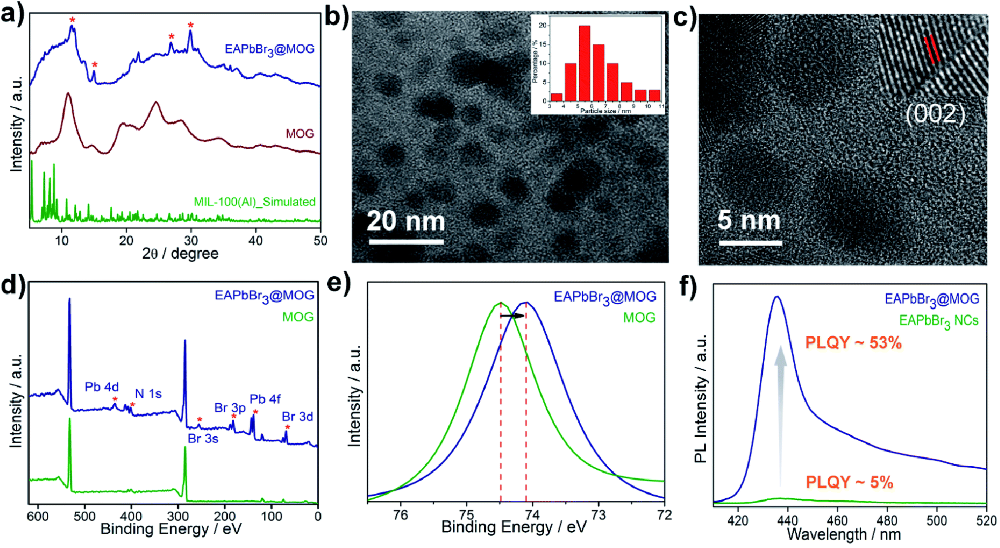 | ||
| Fig. 1 Characterization of EAPbBr3@MOG nanocomposite. (a) PXRD patterns of simulated MIL-100(Al), MOG (pristine) and EAPbBr3@MOG nanocomposite. (*) represents the characteristic diffraction peaks for EAPbBr3 NCs. (b) TEM image of EAPbBr3@MOG nanocomposite. Inset: size distribution histogram of EAPbBr3@MOG nanocomposite. Average size of EAPbBr3 NPs is 5.5 nm. (c) HRTEM image of MAPbBr3 composite material. Inset: shows the lattice fringe of an individual EAPbBr3 NC. (d) Full range of XPS spectra of MOG and EAPbBr3@MOG nanocomposite. (*) indicates the characteristic peaks for EAPbBr3 perovskite NCs. (e) XPS spectra of Al 2p for MOG and EAPbBr3@MOG nanocomposite. (f) PL spectra of EAPbBr3 NCs (PLQY ∼ 5%) and EAPbBr3@MOG nanocomposite (PLQY ∼53%). | ||
The structure of EAPbBr3 has already been reported in the literature and it has a two-dimensional (2D) arrangement.34,35 The characteristic diffraction peak at ∼11.3° confirms the 2D arrangement of the EAPbBr3 NCs. Structural evolutions of the material were studied by TEM analysis and TEM images (Fig. 1b and S13, ESI†) and confirmed that EAPbBr3 NCs are spherical in shape and are dispersed inside the MOG matrix. The particle size distribution histogram for EAPbBr3@MOG (inset in Fig. 1b) shows that the spherically shaped EAPbBr3 NCs have a diameter ranging from 3 to 11 nm, with an average diameter of 5.5 nm. The differently sized NCs are formed in the composite material due to the presence of hierarchical pores in the host MOG matrix.33 The HRTEM images of the EAPbBr3@MOG composite reveal a well-defined lattice spacing according to the crystallographic parameters for EAPbBr3 NCs (Fig. 1c). In the inset in Fig. 1c, the composite shows an interplanar distance of 0.296 nm, which is attributed to the (002) plane of EAPbBr3 NCs.39 Fourier-transform infrared spectroscopy (FTIR) measurements (Fig. S14 and S15, ESI†) also confirm the presence of HBP-NCs inside the MOG matrix. Nitrogen sorption isotherms (Fig. S16, ESI†) show considerably less gas uptake in the case of both composites (514 of m2 g−1 for EAPbBr3@MOG, 522 m2 g−1 for MAPbBr3@MOG) compared with the parent material, i.e. the MOG (778 m2 g−1). This suggests that the perovskite NCs are successfully embedded in the MOG matrix.40 The full-range XPS spectra of the compounds are shown in Fig. 1d and the binding energy positions of different atoms are similar to the literature reports.33,41 In the case of the nanocomposites, the appearance of new signals (Fig. S17 and S18, ESI†) for bromine and lead atoms proves the formation of HBP-NCs in the MOG matrix. Detailed analysis of XPS data (Fig. 1d) show the peak for Al 2p shifted to lower binding energies, from 74.5 to 74.1 eV, with a slight peak broadening for the EAPbBr3@MOG compared with the host MOG (Fig. 1e), suggesting a change in the coordination environment around the Al(III) atoms. It is notable that the negative shift of binding energy for EAPbBr3@MOG occurred due to strong interactions between the MOG framework and the perovskite NCs. The absorption and emission peaks of EAPbBr3@MOG appeared at 398 nm and 436 nm, respectively, while MAPbBr3@MOG showed an absorption peak at 475 nm and an emission band at 492 nm (Fig. S19–S25, ESI†). The long tail originates in the emission spectrum of EAPbBr3@MOG, with a full width at half-maximum height (FWHM) of 18.4 nm (Fig. S19†), due to the presence of different-sized NCs in the composite material.42 Previously, it was also reported that low-dimensional lead halide perovskites exhibited broad band emission due to the formation of self-trapped excitons.43,44 Due to the large size of the ethylammonium cation (EA+), there is a possibility of Jahn–Teller-like octahedral distortion,45 which is responsible for generation of self-trapped excitons. In the EAPbBr3@MOG composite, the tail spans 450 nm to beyond 520 nm and is attributed to the formation of self-trapped excitons. Similar PL peak position, PL intensity and FWHM of different batches of composites confirmed the reproducibility of these materials by this two-step synthetic methodology (Fig. S26 and S27, ESI†). The absolute value of PLQY for the EAPbBr3@MOG nanocomposite was found to be 53% (Fig. 1f) and it is noteworthy that, so far, this is one of the highest reported PLQY values among ethyl cation-containing blue light-emitting hybrid perovskite materials.15,39,45 Time-resolved photoluminescence spectra of perovskite NCs and composites are shown in Fig. S28–S30† and the fitting parameters are listed in Tables S3 and S4.† The decay profiles of both EAPbBr3 NCs and EAPbBr3@MOG composite are fitted to bi-exponential functions, suggesting two different components are associated in the emission spectra. The average lifetime of the EAPbBr3@MOG nanocomposite (3.03 ns) is much longer compared with the EAPbBr3 NCs (0.70 ns) (Table S3†), implying successful encapsulation of NCs inside the MOG matrix.46 The increased lifetimes indicate the elimination of detrimental trap states and that the generated excitons were promoted to a radiative path through surface passivation via the MOG matrix, as a consequence of the uplift of the PLQY value.47 The detrimental non-radiative decay rate constant drops (knr, 0.16 ns−1) significantly compared with the parent EAPbBr3 NCs (knr, 1.39 ns−1) (Table S3, ESI†), resulting in the improved emission behavior of the EAPbBr3@MOG nanocomposite.48 Here, the dramatic improvement in the photoluminescence of the perovskite NCs occurred due to supramolecular interactions between the perovskite material and the MOG matrix. In the as-synthesized EAPbBr3@MOG composite, we believe that the presence of both Al(III) from Al-MOG49,50 and carboxylate oxygens from trimesic acid51,52 largely removes the surface trap states of EAPbBr3 NCs and, consequently, a giant PL enhancement is observed in the composite material.
Stability test
All the stability-related experiments for the nanocomposites were executed maintaining similar conditions, in which bare NCs were readily prone to decompose.22,53 To ensure open-air stability, both composites were kept in the open air for a few months (Fig. 2a, S31 and S32, ESI†) and retention of the original PL intensity (>80%) was found, demonstrating their long-term air stability. The inset in Fig. 2a illustrates the color in the solid state and the PL intensity of the EAPbBr3@MOG remained almost the same, even after four months in the open air, thus proving its long-term environmental stability. Water stability experiments were conducted by immersing the composite materials into water and it was found that, even after 12 hours of immersion, the PL spectra remained almost the same, confirming the outstanding water stability (Fig. 2b, S33 and S34, ESI†). Photostability tests were performed by measuring PL intensity as a function of time under continuous UV light (365 nm) illumination at ambient conditions for 300 hours. Retention of PL intensity (>80%, Fig. S35, ESI†) was found, and the PXRD patterns (Fig. S36, ESI†) of EAPbBr3@MOG remained intact, demonstrating its excellent photostability. The MAPbBr3@MOG composite also showed outstanding stability in the open air, with UV irradiation and even in water media (Fig. S37–S41, ESI†). In the composite materials, a protecting barrier around the perovskite NCs is formed, which shields the unstable EAPbBr3 NCs from various kinds of environmental degradation, including water molecules. Because of these shielding effects by the MOG matrix, the water molecules are unable to penetrate the MOG layer and cannot reach the perovskite NCs, leading to excellent stability in open air, water and under UV light.22–24,54 Additionally, a variety of well-defined smooth and crack-free artificial shapes and sculptures were successfully fabricated with these composites, without the addition of any external binder (Fig. 3a and S42–S46, ESI†).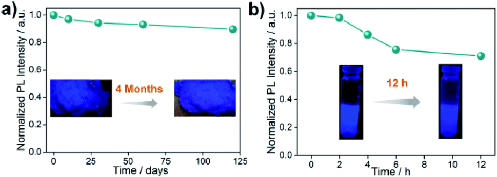 | ||
| Fig. 2 Stability studies of EAPbBr3@MOG nanocomposite. (a) Normalized PL intensity as a function of time stored under open air over a period of 4 months. The inset photographs show the color of the solid material under UV light (365 nm) before and after 4 months. (b) Normalized PL intensity as a function of time in water for different time intervals. Inset photographs show the color of the composites under UV light (365 nm) before and after 12 hours immersed in water. | ||
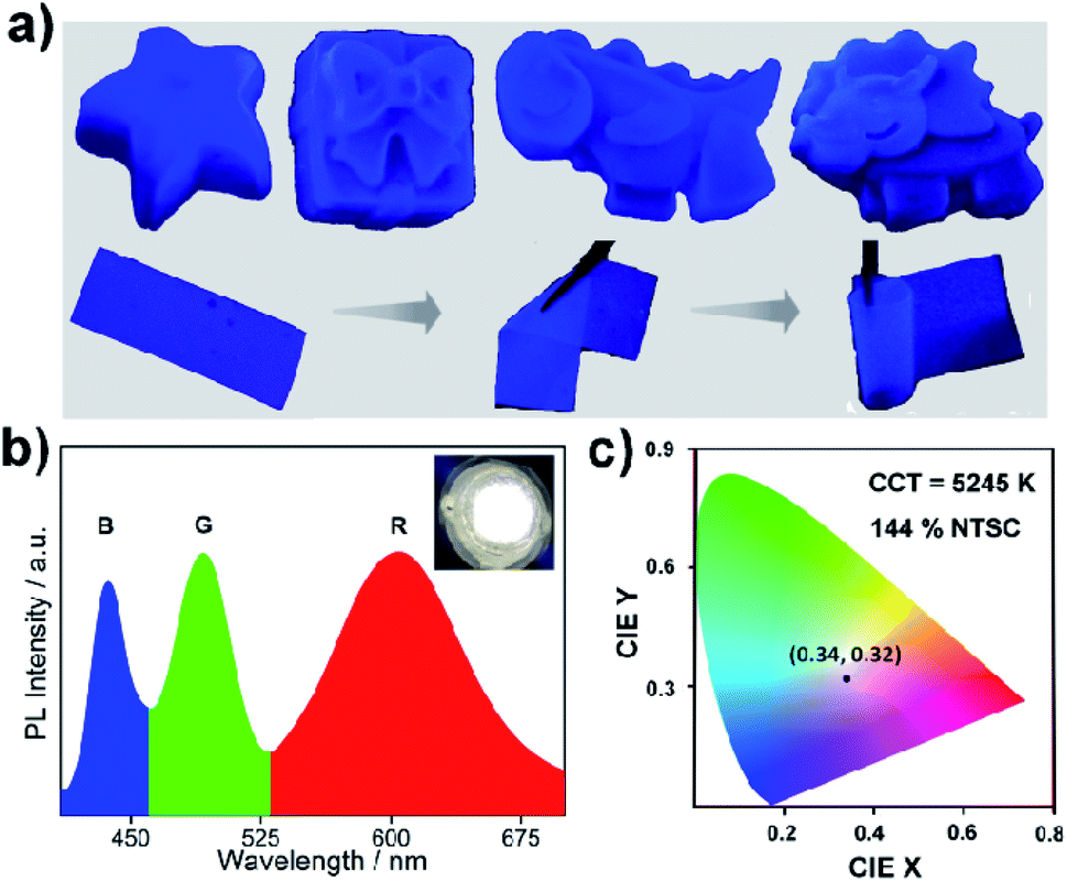 | ||
| Fig. 3 Different sculptures and characterization of as-fabricated WLEDs. (a) Various sculptures and flexible thin films were fabricated from blue emissive EAPbBr3@MOG nanocomposite. The photographs of sculpture and thin film are under UV light (365 nm), showing bright, intense, blue fluorescence. (b) Emission spectrum of white LED fabricated by a combination of blue-emitting EAPbBr3@MOG (B), green-emitting MAPbBr3@MOG (G) and red-emitting Mn(II)-doped EAPbBr3 NCs (R) deposited on a UV chip. Inset: shows a photograph of the white LED with an applied current of 20 mA. (c) CIE color coordinates of the as-fabricated white LEDs (x: 0.34, y: 0.32). | ||
Flexible thin films were successfully prepared using these composites for diverse practical applications (Fig. 3a and S47, ESI†). Table S5† shows a comparison of the PL properties and stability of the intense blue light-emitting (λmax < 440 nm) hybrid perovskites developed so far. This table highlights that the PL properties of our system are comparable to those of the brightest blue light emitters related to hybrid perovskite materials, and with superior stability over other systems.
Fabrication of WLEDs
As a proof of concept for lighting applications, blue emissive EAPbBr3@MOG, green emissive MAPbBr3@MOG and red emissive Mn(II)-doped EAPbBr3@MOG (prepared through mixing Mn(II) salt with EAPbBr3 NCs) (Fig. S48 and S49, ESI†) were mixed in the proper ratios and then coupled with a commercially available UV chip to fabricate a WLED device.55,56Fig. 3b shows the positions of the emission peak maxima obtained for the WLED, which are in good agreement with the steady-state PL peaks. The photograph of the operating WLED is shown as an inset in Fig. 3b. The Commission Internationale de l'Eclairage (CIE) chromaticity coordinates of the as-prepared WLED were (0.34, 0.32) and the color gamut coverage was as high as 144% (Fig. 3c and S50, ESI†) of the NTSC standard, benefiting from the narrow emission spectra of the blue and green emissive perovskite composites. The correlated color temperature (CCT) was 5245 K, which corresponded to so-called white daylight. The WLED maintained its color purity for all components even after 24 hours in the open air, confirming its stability under ambient conditions (Fig. S51, ESI†).Conclusions
In summary, we have developed a straightforward two-step approach for the synthesis of bright, intense, blue light-emitting perovskite@MOG nanocomposites, where perovskite NCs were embedded inside a porous MOG matrix for the first time. Here, the MOG matrix offers dual benefits to the perovskite NCs; namely, it serves as a protective barrier against degradation under working conditions and it enhances the luminescence properties dramatically. Additionally, the flexible nanocomposites were easily fabricated into different, desirable three-dimensional artificial structures for practical use. Finally, the as-synthesized nanocomposites were shown to be applicable as color converters for constructing WLEDs. The present study elucidates the simple fabrication of a cheap, high-quality perovskite-based blue light emitter for future display applications.Conflicts of interest
There are no conflicts to declare.Acknowledgements
S. M. is thankful to U.G.C. for a research fellowship. T. N. M. thanks SERB (SB/FT/CS-116/2014) for financial support. S. F. acknowledges the DST-Inspire fellowship (DST/INSPIRE/03/2016/001694). S. K. G. acknowledges SERB (Project No. EMR/2016/000410) and DST Nanomission Thematic Unit for funding.Notes and references
- C. C. Stoumpos and M. G. Kanatzidis, Acc. Chem. Res., 2015, 48, 2791–2802 CrossRef CAS.
- J. Heo, S. H. Im, J. H. Noh, T. N. Mandal, C.-S. Lim, J. A. Chang, Y. Lee, H.-J. Kim, A. Sarkar, M. K. Nazeeruddin, M. Grätzel and S. I. Seok, Nat. Photonics, 2013, 7, 486–491 CrossRef CAS.
- J. S. Manser, J. A. Christians and P. V. Kamat, Chem. Rev., 2016, 116, 12956–13008 CrossRef CAS PubMed.
- M. M. Lee, J. Teuscher, T. Miyasaka, T. N. Murakami and H. J. Snaith, Science, 2012, 338, 643–647 CrossRef CAS PubMed.
- L. Protesescu, S. Yakunin, M. I. Bodnarchuk, F. Krieg, R. Caputo, C. H. Hendon, R. X. Yang, A. Walsh and M. V. Kovalenko, Nano Lett., 2015, 15, 3692–3696 CrossRef CAS PubMed.
- Z.-K. Tan, R. S. Moghaddam, M. L. Lai, P. Docampo, R. Higler, F. Deschler, M. Price, A. Sadhanala, L. M. Pazos, D. Credgington, F. Hanusch, T. Bein, H. J. Snaith and R. H. Friend, Nat. Nanotechnol., 2014, 9, 687–692 CrossRef CAS PubMed.
- X. Dai, Y. Deng, X. Peng and Y. Jin, Adv. Mater., 2017, 29, 1607022 CrossRef PubMed.
- M. V. Kovalenko, L. Protesescu and M. I. Bodnarchuk, Science, 2017, 358, 745–750 CrossRef CAS PubMed.
- B. S. Sutherland, Joule, 2018, 2, 2199–2201 CrossRef.
- B. J. Bohn, Y. Tong, M. Gramlich, M. L. Lai, M. Doblinger, K. Wang, R. L. Z. Hoye, P. Muller-Buschbaum, S. D. Stranks, A. S. Urban, L. Polavarapu and J. Feldmann, Nano Lett., 2018, 18, 5231–5238 CrossRef CAS PubMed.
- W. Liu, W. P. Lusting and J. Li, EnergyChem, 2019, 1, 100008 CrossRef.
- Z. Wei, Z.-Y. Gu, R. K. Arvapally, Y.-P. Chen, R. N. McDougald Jr, J. F. Ivy, A. A. Yakovenko, D. Feng, M. A. Omary and H.-C. Zhou, J. Am. Chem. Soc., 2014, 136, 8269–8276 CrossRef CAS PubMed.
- G. H. Ahmed, J. K. El-Demellawi, J. Yin, J. Pan, D. B. Velusamy, M. N. Medhili, E. Alarousu, O. M. Bakr, H. N. Alshareef and O. F. Mohammed, ACS Energy Lett., 2018, 3, 2301–2307 CrossRef CAS.
- Y. Wu, C. Wei, X. Li, Y. Li, S. Qiu, W. Shen, B. Cai, Z. Sun, D. Yang, Z. Deng and H. Zeng, ACS Energy Lett., 2018, 3, 2030–2037 CrossRef CAS.
- X. Gong, O. Voznyy, A. Jain, W. Liu, R. Sabatini, Z. Piontkowski, G. Walters, G. Bappi, S. Nokhrin, O. Bushuyev, M. Yuan, R. Comin, D. McCamant, S. O. Kelley and E. H. Sargent, Nat. Mater., 2018, 17, 550–556 CrossRef CAS PubMed.
- T. M. Brenner, D. A. Egger, L. Kronik, G. Hodes and D. Cahen, Nat. Rev. Mater., 2016, 1, 15007 CrossRef CAS.
- Y. Wu, X. Li and H. Zeng, ACS Energy Lett., 2019, 4, 673–681 CrossRef CAS.
- J. Xing, Y. Zhao, M. Askerka, L. N. Quan, X. Gong, W. Zhao, J. Zhao, H. Tan, G. Long, L. Gao, Z. Yang, O. Voznyy, J. Tang, Z.-H. Lu, Q. Xiong and E. H. Sargent, Nat. Commun., 2018, 9, 3541 CrossRef PubMed.
- Y. Jiang, C. Qin, M. Cui, T. He, K. Liu, Y. Huang, M. Luo, L. Zhang, H. Xu, S. Li, J. Wei, Z. Liu, H. Wang, G.-H. Kim, M. Yuan and J. Chen, Nat. Commun., 2019, 10, 1868 CrossRef PubMed.
- N. K. Kumawat, X.-K. Liu, D. Kabra and F. Gao, Nanoscale, 2019, 11, 2109–2120 RSC.
- M. K. Gangishetty, S. Hou, Q. Quan and D. N. Conreve, Adv. Mater., 2018, 30, 1706226 CrossRef PubMed.
- S. Mollick, T. N. Mandal, A. Jana, S. Fajal, A. V. Desai and S. K. Ghosh, ACS Appl. Nano Mater., 2019, 2, 1333–1340 CrossRef CAS.
- H. He, Y. Cui, B. Li, B. Wang, C. Jin, J. Yu, L. Yao, Y. Yang, B. Chen and G. Qian, Adv. Mater., 2019, 31, 1806897 Search PubMed.
- Z. Chen, Z.-G. Gu, W.-Q. Fu, F. Wang and J. Zhang, ACS Appl. Mater. Interfaces, 2016, 8, 28737–28742 CrossRef CAS PubMed.
- X.-Y. Liu, K. Xiang, Y. Li, C.-K. Tsung and J. Li, J. Am. Chem. Soc., 2019, 141, 14807–14813 CrossRef CAS PubMed.
- V. Urbanova, K. Jayaramulu, A. Schneemann, S. Kment, R. A. Fischer and R. Zboril, ACS Appl. Mater. Interfaces, 2018, 10, 41089–41097 CrossRef CAS PubMed.
- X. Wang, X. Lian, Z. Zhang and H. Gao, ACS Energy Lett., 2019, 4, 1446–1454 CrossRef CAS.
- X. Yang, G. Zhang and D. Zhang, J. Mater. Chem., 2012, 22, 38–50 RSC.
- Y. Yang, J. T. Lee, T. Liyanage and R. Sardar, J. Am. Chem. Soc., 2019, 141, 1526–1536 CrossRef CAS PubMed.
- G. Li, F. W. R. Rivarola, N. J. L. K. Davis, S. Bai, T. C. Jellicoe, F. de la Pena, S. Hou, C. Ducati, F. Gao, R. H. Friend, N. C. Greenham and Z.-K. Tan, Adv. Mater., 2016, 28, 3528–3534 CrossRef CAS PubMed.
- V. Malgras, S. Tominaka, J. W. Ryan, J. Henzie, T. Takei, K. Ohara and Y. Yamauchi, J. Am. Chem. Soc., 2016, 138, 13874–13881 CrossRef CAS PubMed.
- A. Loiudice, S. Saris, E. Oveisi, D. T. L. Alexander and R. Buonsanti, Angew. Chem., Int. Ed., 2017, 56, 10696–10701 CrossRef CAS PubMed.
- K. Jayaramulu, F. Geyer, M. Petr, R. Zboril, D. Vollmer and R. A. Fischer, Adv. Mater., 2017, 29, 1605307 CrossRef PubMed.
- B. Luo, Y. Guo, X. Li, Y. Xiao, X. Huang and J. Z. Zhang, J. Phys. Chem. C, 2019, 123, 14239–14245 CrossRef CAS.
- S. Yun, A. Kirakosyan, S.-G. Yoon and J. Choi, ACS Sustainable Chem. Eng., 2018, 6, 3733–3738 CrossRef CAS.
- G. C. Papavassiliou, G. Pagona, N. Karousis, G. A. Mousdis, I. Koutselas and A. Vassilakopoulou, J. Mater. Chem., 2012, 22, 8271–8280 RSC.
- J. C. de Mello, H. F. Wittmann and R. H. Friend, Adv. Mater., 1997, 9, 230–232 CrossRef CAS.
- F. Zhang, H. Zhong, C. Chen, X.-G. Wu, X. Hu, H. Huang, J. Han, B. Zou and Y. Dong, ACS Nano, 2015, 9, 4533–4542 CrossRef CAS PubMed.
- Q. Wang, J. Ren, X.-F. Peng, X.-X. Ji and X.-H. Yang, ACS Appl. Mater. Interfaces, 2017, 9, 29901–29906 CrossRef CAS PubMed.
- X. Gu, Z.-H. Lu, H.-L. Jiang, T. Akita and Q. Xu, J. Am. Chem. Soc., 2011, 133, 11822–11825 CrossRef CAS PubMed.
- C. Zhang, B. Wang, W. Li, S. Huang, L. Kong, Z. Li and L. Li, Nat. Commun., 2017, 8, 1138 CrossRef PubMed.
- M. Mittal, A. Jana, S. Sarkar, P. Mahadevan and S. Sapra, J. Phys. Chem. Lett., 2016, 7, 3270–3277 CrossRef CAS PubMed.
- M. D. Smith, B. A. Connor and H. I. Karunadasa, Chem. Rev., 2019, 119, 3104–3139 CrossRef CAS PubMed.
- H. Lin, C. Zhou, J. Neu, Y. Zhou, D. Han, S. Chen, M. Worku, M. Chaaban, S. Lee, E. Berkwits, T. Siegrist, M.-H. Du and B. Ma, Adv. Opt. Mater., 2019, 7, 1801474 CrossRef.
- D. Cortecchia, J. Yin, A. Petrozza and C. Soci, J. Mater. Chem. C, 2019, 7, 4956–4969 RSC.
- Y. Wang, J. He, H. Chen, J. Chen, R. Zhu, P. Ma, A. Towers, Y. Lin, A. J. Gesquiere, S.-T. Wu and Y. Dong, Adv. Mater., 2016, 28, 10710–10717 CrossRef CAS PubMed.
- Z. Li, L. Kong, S. Huang and L. Li, Angew. Chem., Int. Ed., 2017, 56, 8134–8138 CrossRef CAS PubMed.
- N. Mondal, A. De and A. Samanta, ACS Energy Lett., 2019, 4, 32–39 CrossRef CAS.
- J. T.-W. Wang, Z. Wang, S. Pathak, W. Zhang, D. W. deQuilettes, F. Wisnivesky-Rocca-Rivarola, J. Huang, P. K. Nayak, J. B. Patel, H. A. M. Yusof, Y. Vaynzof, R. Zhu, I. Ramirez, J. Zhang, C. Ducati, C. Grovenor, M. B. Johnston, D. S. Ginger, R. J. Nicholas and H. J. Snaith, Energy Environ. Sci., 2016, 9, 2892–2901 RSC.
- T. Kyomen, R. Sakamoto, N. Sakamoto, S. Kunugi and M. Itoh, Chem. Mater., 2005, 17, 3200–3204 CrossRef CAS.
- D. Lu, Y. Zhang, M. Lai, A. Lee, C. Xie, T. Lei, Z. Lin, C. S. Kley, J. Huang, E. Rabani and P. Yang, Nano Lett., 2018, 18, 6967–6973 CrossRef CAS PubMed.
- Y. Tian, M. Peter, E. Unger, M. Abdellah, K. Zheng, T. Pullerits, A. Yartsev, V. Sundstron and I. G. Scheblykin, Phys. Chem. Chem. Phys., 2015, 17, 24978–24987 RSC.
- H. Sun, Z. Yang, M. Wei, W. Sun, X. Li, S. Ye, Y. Zhao, H. Tan, E. L. Kynaston, T. B. Schon, H. Yan, Z.-H. Lu, G. A. Ozin, E. H. Sargent and D. S. Seferos, Adv. Mater., 2017, 29, 1701153–1701162 CrossRef PubMed.
- D. Zhang, Y. Xu, Q. Liu and Z. Xia, Inorg. Chem., 2018, 57, 4613–4619 CrossRef CAS PubMed.
- D. Chen, J. Li, X. Chen, J. Chen and J. Zhong, ACS Appl. Mater. Interfaces, 2019, 11, 10059–10067 CrossRef CAS PubMed.
- M. Bidikoudi, E. Fresta and R. D. Costa, Chem. Commun., 2018, 54, 8150–8169 RSC.
Footnotes |
| † Electronic supplementary information (ESI) available: Details of characterization, stability test in detail, and photocatalysis graphs. See DOI: 10.1039/c9sc03829a |
| ‡ These authors contributed equally. |
| This journal is © The Royal Society of Chemistry 2019 |