
 Open Access Article
 This Open Access Article is licensed under a Creative Commons Attribution-Non Commercial 3.0 Unported Licence
Enhanced coupling through π-stacking in imidazole-based molecular junctions†
Tianren
Fu
a,
Shanelle
Smith
b,
María
Camarasa-Gómez
c,
Xiaofang
Yu
b,
Jiayi
Xue
bd,
Colin
Nuckolls
 *a,
Ferdinand
Evers
*c,
Latha
Venkataraman
*ae and
Sujun
Wei
*b
*a,
Ferdinand
Evers
*c,
Latha
Venkataraman
*ae and
Sujun
Wei
*b
aDepartment of Chemistry, Columbia University, New York, New York 10027, USA. E-mail: cn37@columbia.edu; lv2117@columbia.edu
bDepartment of Chemistry, Queensborough Community College of the City University of New York, Bayside, New York 11364, USA. E-mail: SWei@qcc.cuny.edu
cInstitute of Theoretical Physics, University of Regensburg, 93040 Regensburg, Germany. E-mail: ferdinand.evers@physik.uni-regensburg.de
dDepartment of Chemistry and Biochemistry, Queens College of the City University of New York, Flushing, New York 11367, USA
eDepartment of Applied Physics, Columbia University, New York, New York 10027, USA
First published on 16th September 2019
Abstract
We demonstrate that imidazole based π–π stacked dimers form strong and efficient conductance pathways in single-molecule junctions using the scanning-tunneling microscope-break junction (STM-BJ) technique and density functional theory-based calculations. We first characterize an imidazole-gold contact by measuring the conductance of imidazolyl-terminated alkanes (im-N-im, N = 3–6). We show that the conductance of these alkanes decays exponentially with increasing length, indicating that the mechanism for electron transport is through tunneling or super-exchange. We also reveal that π–π stacked dimers can be formed between imidazoles and have better coupling than through-bond tunneling. These experimental results are rationalized by calculations of molecular junction transmission using non-equilibrium Green's function formalism. This study verifies the capability of imidazole as a Au-binding ligand to form stable single- and π-stacked molecule junctions at room temperature.
Imidazole is an aromatic five-member-ring structure with two nitrogen atoms, one pyridine-like and one pyrrole-like nitrogen (N-3 and N-1 as shown in Fig. 1). The lone pair electrons on the pyridine-nitrogen coordinate with metals or protons. Additionally, the electron-rich characteristic of imidazole also enables versatile intermolecular non-covalent interactions, such as accepting hydrogen bonds or enhancing π–π interactions. Imidazole thus has varied functionality. For example, as a functional group of the amino acid histidine, it is the active binding site in superoxide dismutases;1,2 it also acts as a Brønsted base in serine endopeptidases.3 In metal organic frameworks (MOFs), it is used as a bidentate but non-chelating ligand.4 Despite these broad functionalities, the electronic characteristics of imidazole as a Au-binding ligand have not yet been tested.
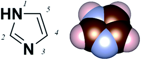 | ||
| Fig. 1 The molecular structure of imidazole and IUPAC numbering of atoms. | ||
Here, we applied the scanning tunneling microscope-based break-junction (STM-BJ) method to create and characterize imidazole-based molecular junctions.5,6 We synthesized four imidazole-terminated alkane molecules with a 1,ω-di(imidazol-1-yl)alkane (im-3-im, im-4-im, im-5-im and im-6-im) chemical structure, as shown in Fig. 2a. The synthesis is detailed in the ESI.†
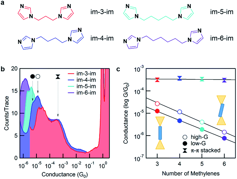 | ||
Fig. 2 (a) The chemical structures of im-N-im molecules. (b) Logarithmically binned conductance histograms (100 bins per decade) for all four molecules generated from 15![[thin space (1/6-em)]](https://www.rsc.org/images/entities/char_2009.gif) 000 traces each. The three peaks, two that change with the molecular backbone length and one that is independent of the backbone length, are indicated by arrows for im-4-im. Histograms are terminated at the noise floor. (c) Molecular junction conductance, determined from a Gaussian fit, is plotted against the number of methylene units in the backbone. The β values determined from the fit are 0.93 per methylene (low-G) and per methylene 1.01 (high-G). 000 traces each. The three peaks, two that change with the molecular backbone length and one that is independent of the backbone length, are indicated by arrows for im-4-im. Histograms are terminated at the noise floor. (c) Molecular junction conductance, determined from a Gaussian fit, is plotted against the number of methylene units in the backbone. The β values determined from the fit are 0.93 per methylene (low-G) and per methylene 1.01 (high-G). | ||
STM-BJ measurements are conducted under ambient conditions at room temperature as has been described before.5 Junctions are formed between a Au substrate and tip from a ∼1 mM solution of the target molecule in 1,2,4-trichlorobenzene (TCB). Each individual measurement starts by smashing the tip into the substrate to create a Au–Au contact. The tip is then withdrawn while the conductance (current/voltage) is measured as a function of the relative tip/substrate displacement and this is repeated at least 5000 times for each molecule. The individual traces are compiled into logarithmically binned conductance histograms.7
Fig. 2b shows 1D conductance histograms for all four molecules. 2D conductance–displacement histograms are shown in ESI Fig. S1.† All measurements are performed at a 900 mV bias. Note that the bias does not affect conductance for these molecules as shown by measurements at intermediate biases in ESI Fig. S2.† A clear peak at ∼1 G0 (G0 = 2e2/h, the conductance quantum) is seen due to the reproducible formation of a single atom Au contact. Molecular junction conductance peaks occur over a range of 10−4 to 10−6G0 and show decreasing conductance with increasing backbone length. This can be attributed to ballistic tunnelling transmission through the molecular junction. In addition, for every histogram, there is a broad feature at around 10−3G0 which we attribute to an intermolecular π–π stacked complex that we will discuss in detail further below.8–13 Further inspection of the molecular conductance peak reveals that it is actually two peaks, similar to what is observed for pyridine-based linkers.14–16 Since the imidazole linker binds to Au with its pyridine-nitrogen, it can form a vertical, primarily σ-coupled junction (left) or a tilted σ- and π-coupled junction (right) as illustrated in the inset of Fig. 2c. As the differences between these two binding configurations have been investigated in detail for pyridine linkers before,16,17 in the following discussion, we will focus primarily on the lower-conducting σ-coupled configuration.
Fig. 2c shows the plot of the peak conductance value of each molecule against the molecular length. The solid circles represent the conductance of the σ-coupled configuration with a lower conductance (low-G), and the hollow circles represent the conductance of the tilted configuration (high-G). Both series show an exponential decay in conductance with increasing molecular length. We fit these experimental data with the tunnelling transmission model, GN = Ae−βN, and obtain a decay constant, β = 0.93 and 1.01 per methylene for the low-G and high-G configurations respectively. This β value agrees with measurements of alkyl molecules with other linkers18,19 and confirms that these follow a tunnelling mechanism. By extending the fit to N = 0, we estimate the conductance of a molecule with no carbon bridging the two imidazole groups; the inverse of this conductance serves as a metric for the linker contact resistance. For the imidazole linker, we obtain a contact resistance of 65 MΩ for the low-G series. As a comparison, the contact resistance for some other common linkers are as follows: –SMe: 0.27 MΩ, –NH2: 0.37 MΩ and –PMe2: 0.13 MΩ.18 We can also compare imidazole with pyridine which has a contact resistance of 23 MΩ as determined from a direct measurement of 4,4′-bipyridine.15 Although clearly larger than small linkers, imidazole is comparable to pyridine.
We now turn to transport calculations based on density functional theory (DFT) and compute electronic transmission through Au-im-N-im-Au model junctions. We employ the FHI-aims package20,21 with a PBE exchange–correlation functional22 and apply a non-equilibrium Green's function formalism implemented within the AITRANSS package.23,24 The structure of a low-Gim-4-im junction is shown in Fig. 3a, using the VESTA program.25 Each electrode consists of a pyramidal cluster of 55 Au atoms, arranged in 6 layers in the (111) direction with a closest interatomic distance of 2.88 Å. The im-N-im molecules are fully relaxed in an all anti conformation in the gas phase and imidazole is bound to the apex atom of the Au electrode in a vertical geometry, a structure that represents the σ-coupled configuration.
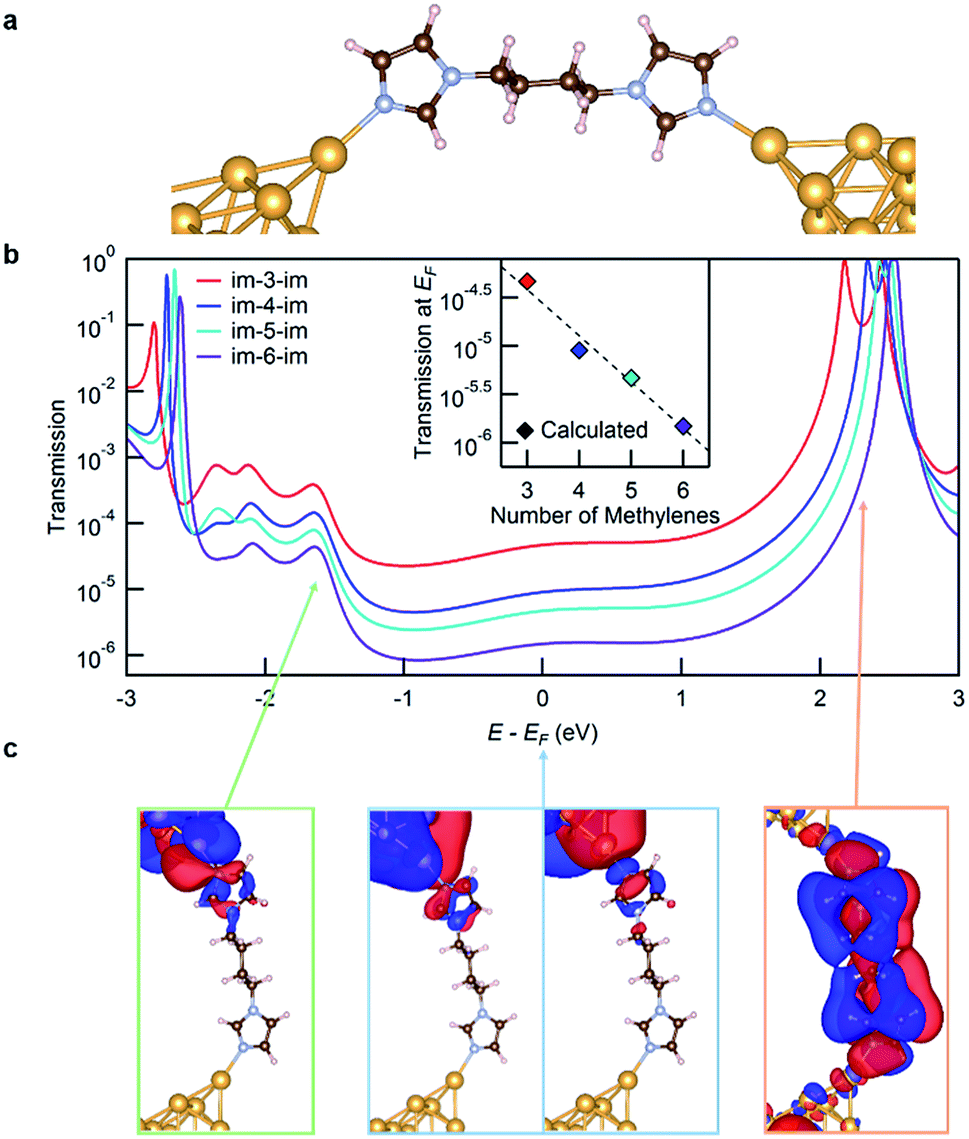 | ||
| Fig. 3 (a) The structure of the im-4-im junction. (b) The calculated transmission functions of all the four molecules. Inset: linear fit of transmission at the Fermi energy of each molecular junction. (c) The scattering states for the im-4-im junction determined at the Fermi energy and at the energies corresponding to the two peaks closest to the Fermi energy, as indicated in the figure. | ||
The transmission functions for all four molecules studied are shown in Fig. 3b. The transmission at the Fermi energy (EF) has a strong contribution from the molecular HOMO−4 and HOMO−2 based σ-channels that decay across the molecular backbone, as can be seen from the isosurface plots for im-4-im shown in Fig. 3c (the structures in the blue frame). The transmission peak at around −1.6 eV relative to EF (on the occupied side) represents transmission through the molecular HOMO−8 which is also primarily a σ-based orbital (the structure in the green frame). The transmission peak at around +2.3 eV relative to EF results from the weakly coupled π-based molecular LUMO (the structure in the orange frame). The transmission at EF decreases exponentially with increasing molecular length, in agreement with the experimental results. The calculated conductance values, obtained by applying the Landauer formula to the transmission at EF, are plotted against the molecular length in the inset of Fig. 3b. The calculations overestimate conductance due to known errors with DFT26 which in turn can also alter the calculated β value. We find that the calculated β value is 1.10/methylene, slightly higher than the experimental one.
We now turn to the molecular conductance peak seen around 10−3G0 for all the molecules in this series as shown in Fig. 2b. We attribute this peak to junctions formed by an intermolecular π–π stacked dimer (see Fig. 4a and b). Such a dimer has been observed in aniline derivatives where the contribution of the N-pz orbital is significant to enhance the intermolecular interaction.27 The pyrrole nitrogen on the imidazole ring can play a similar role, enhancing the electron density in the imidazole π system and augmenting π–π interactions. To confirm this hypothesis, we measure the conductance of 1-methylimidazole (im-1) which has only one Au-binding site. The 1D histogram from STM-BJ measurements of im-1 is shown in Fig. 4c, together with the histogram of im-4-im. Im-1 gives a single peak at ∼10−3G0 which overlaps with the peak also observed for all im-N-im molecules.
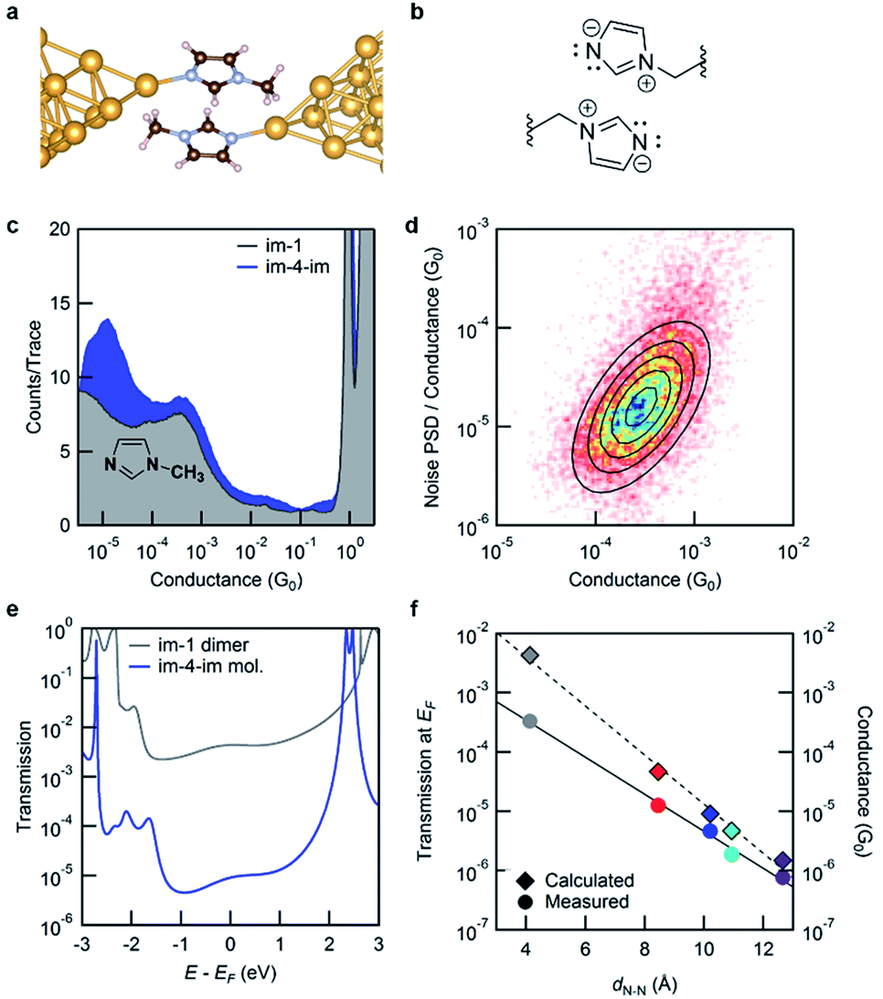 | ||
| Fig. 4 (a) The structure of a π–π stacked 1-methylimidazole (im-1) dimer junction used in the DFT calculations. (b) The charge-separated resonance state that stabilizes the π–π stacked dimer. (c) Logarithmically binned conductance histogram for im-1 and im-4-im measurements. (d) Two-dimensional histogram of PSD/G against the average junction conductance G. (e) Calculated transmission functions of an im-1 dimer junction along with that of the molecular im-4-im junction. (f) The transmission at the Fermi energy of im-1, together with im-N-im plotted against the junction N–N distance (left axis). The corresponding experimental data are also shown (right axis). | ||
Since im-1 has only one Au-binding site, it can only form a π–π stacked junction. We therefore use flicker noise measurements, which have been used to distinguish through-space transmission from through-bond transmission28 to confirm this hypothesis. Flicker noise measurements are conducted by first forming an im-1 dimer junction, holding this for 150 ms and analyzing the conductance, measured with a 100 kHz bandwidth. Two parameters are calculated from the conductance data while the junction is held: the average conductance (G) and the normalized noise power in the form of power spectrum density (PSD). The PSD is obtained from the square of the integral of the discrete Fourier transform of the measured conductance between 100 Hz to 1000 Hz. The lower frequency limit is constrained by the mechanical stability of the setup. The upper limit is determined by the input noise of the current amplifier. Using these parameters, we create 2D histograms of the normalized noise power against the average conductance from 8556 traces. The relationship between noise power and conductance is extracted by determining the scaling exponent (N) for which PSD/GN and G are not correlated. We have previously shown that the relationship between the flicker noise PSD and conductance G follows power law dependence (PSD ∼ GN) with the exponent N being indicative of the electronic coupling type. N close to 2 indicates a through-space coupled molecular junction, while an exponent N of 1 indicates through-bond coupling. Fig. 4d shows the 2D histogram of PSD/G against G where a clear positive correlation is visible. For im-1, the correlation between PSD/GN and G becomes zero when N = 1.9. This is a clear indication of through-space transmission. We can therefore attribute the conductance peak at around 10−3G0 to one that involves a through-space coupled intermolecular imidazole dimer. Analogous measurements on im-4-im show that the conductance peak seen around 10−3G0 corresponds to a through-space coupled junction while that seen at 10−5G0 corresponds to a through-bond coupled junction (see the ESI Fig. S5†).
To compare this with the calculated transmission, we model the junction as illustrated in Fig. 4a; the geometry is optimized within DFT including van der Waals interactions following the methods developed by Tkatchenko and Scheffler.29 We find that the DFT-relaxed structure has the two im-1 molecules separated by a ∼3.3 Å gap and stabilized by 0.41 eV when compared to two isolated molecules. For the imidazole ring, an electron-rich pyrrole nitrogen and an electron-withdrawing pyridine nitrogen increase the dominance of its charge-separated resonance structure as shown in Fig. 4b. Thus, the imidazole π–π stacked dimer is more strongly bound than the benzene dimer (which is stabilized by only 0.15 eV). The transmission across this junction is shown in Fig. 4e. At EF, the transmission of the dimer im-1 is ∼100 times that of the molecular im-4-im junction, in agreement with the experiment. For the π–π stacked dimer junction of im-4-im, the calculated transmission is close to that of the dimer im-1 junction (see the ESI†). The results here confirm that the conductance peaks at around 10−3G0 in Fig. 2b arise from intermolecular π–π stacked dimer junctions as shown in Fig. 4b, and thus the length of the alkyl chain in the im-N-im series is not important. In Fig. 4f, we plot the transmission at EF and the measured conductance against the calculated through-space distance between the two imidazole nitrogen atoms that are directly bound to Au atoms. Interestingly, the conductance of the π–π stacked dimer falls on the same line as that fitted through the conductance of the four im-N-im junctions. This indicates that the π–π stacked dimer junction has a transmission that is comparable to that of a single-molecule junction (albeit of much shorter length), in contrast to what is typically expected for such weakly coupled systems.30
In summary, we have investigated the ability of imidazole to function as an aurophilic linker for molecular junctions using the STM-BJ technique. We find that the conductance of four imidazole-terminated alkanes has a β value that is consistent with that found for other linkers. This provides an outlook to direct measurement of the electronic properties of some imidazole-containing biologically relevant systems. Importantly, we also demonstrated that imidazole can form stable π–π stacked dimers that have a relatively high through-space conductance, which therefore function as the smallest functional group forming stable π–π stacked dimers.
Conflicts of interest
There are no conflicts to declare.Acknowledgements
M. C.-G. thanks D. Hernangómez-Pérez for fruitful discussions. We acknowledge financial support from the National Science Foundation under award grant CHE-1764256. S. W. thanks the Professional Staff Congress of the City University of New York (PSC-CUNY) Research Award Program (PSC-CUNY Award #60261-00 48) for funding. X. Y., J. X. and S. W. acknowledge support from the CUNY Research Scholars Program, the US Department of Education Minority Science and Engineering Improvement Program (Award #P120A140057) and the National Institute of Health Bridges to the Baccalaureate Program (Award # 5R25GM065096). M. C.-G. and F. E. are grateful for the financial support from the German Research Foundation through the Collaborative Research Center SFB1277 (project B01) and the Research Training Group GRK 1570. We thank CUNY Queens College NMR Director Dr Gopal Subramaniam for assistance.Notes and references
- S. V. Antonyuk, R. W. Strange, S. L. Marklund and S. S. Hasnain, J. Mol. Biol., 2009, 388, 310–326 CrossRef CAS PubMed.
- J. A. Tainer, E. D. Getzoff, J. S. Richardson and D. C. Richardson, Nature, 1983, 306, 284–287 CrossRef CAS PubMed.
- L. Polgar, Cell. Mol. Life Sci., 2005, 62, 2161–2172 CrossRef CAS PubMed.
- K. S. Park, Z. Ni, A. P. Cote, J. Y. Choi, R. D. Huang, F. J. Uribe-Romo, H. K. Chae, M. O'Keeffe and O. M. Yaghi, Proc. Natl. Acad. Sci. U. S. A., 2006, 103, 10186–10191 CrossRef CAS PubMed.
- L. Venkataraman, J. E. Klare, I. W. Tam, C. Nuckolls, M. S. Hybertsen and M. L. Steigerwald, Nano Lett., 2006, 6, 458–462 CrossRef CAS PubMed.
- B. Q. Xu and N. J. Tao, Science, 2003, 301, 1221–1223 CrossRef CAS PubMed.
- M. T. Gonzalez, S. M. Wu, R. Huber, S. J. van der Molen, C. Schonenberger and M. Calame, Nano Lett., 2006, 6, 2238–2242 CrossRef CAS PubMed.
- S. M. Wu, M. T. Gonzalez, R. Huber, S. Grunder, M. Mayor, C. Schonenberger and M. Calame, Nat. Nanotechnol., 2008, 3, 569–574 CrossRef CAS PubMed.
- S. Martin, I. Grace, M. R. Bryce, C. S. Wang, R. Jitchati, A. S. Batsanov, S. J. Higgins, C. J. Lambert and R. J. Nichols, J. Am. Chem. Soc., 2010, 132, 9157–9164 CrossRef CAS PubMed.
- K. Yoshida, I. V. Pobelov, D. Z. Manrique, T. Pope, G. Mészáros, M. Gulcur, M. R. Bryce, C. J. Lambert and T. Wandlowski, Sci. Rep., 2015, 5, 9002 CrossRef CAS PubMed.
- M. T. González, E. Leary, R. García, P. Verma, M. Á. Herranz, G. Rubio-Bollinger, N. Martín and N. Agraït, J. Phys. Chem. C, 2011, 115, 17973–17978 CrossRef.
- W. Hong, H. Valkenier, G. Mészáros, D. Z. Manrique, A. Mishchenko, A. Putz, P. M. García, C. J. Lambert, J. C. Hummelen and T. Wandlowski, Beilstein J. Nanotechnol., 2011, 2, 699–713 CrossRef PubMed.
- J.-T. Zheng, R.-W. Yan, J.-H. Tian, J.-Y. Liu, L.-Q. Pei, D.-Y. Wu, K. Dai, Y. Yang, S. Jin, W. Hong and Z.-Q. Tian, Electrochim. Acta, 2016, 200, 268–275 CrossRef CAS.
- A. Borges, E. D. Fung, F. Ng, L. Venkataraman and G. C. Solomon, J. Phys. Chem. Lett., 2016, 7, 4825–4829 CrossRef CAS PubMed.
- M. Kamenetska, S. Y. Quek, A. C. Whalley, M. L. Steigerwald, H. J. Choi, S. G. Louie, C. Nuckolls, M. S. Hybertsen, J. B. Neaton and L. Venkataraman, J. Am. Chem. Soc., 2010, 132, 6817–6821 CrossRef CAS PubMed.
- T. Kim, P. Darancet, J. R. Widawsky, M. Kotiuga, S. Y. Quek, J. B. Neaton and L. Venkataraman, Nano Lett., 2014, 14, 794–798 CrossRef CAS PubMed.
- S. Y. Quek, M. Kamenetska, M. L. Steigerwald, H. J. Choi, S. G. Louie, M. S. Hybertsen, J. B. Neaton and L. Venkataraman, Nat. Nanotechnol., 2009, 4, 230–234 CrossRef CAS PubMed.
- Y. S. Park, A. C. Whalley, M. Kamenetska, M. L. Steigerwald, M. S. Hybertsen, C. Nuckolls and L. Venkataraman, J. Am. Chem. Soc., 2007, 129, 15768–15769 CrossRef CAS PubMed.
- C. Li, I. Pobelov, T. Wandlowski, A. Bagrets, A. Arnold and F. Evers, J. Am. Chem. Soc., 2008, 130, 318–326 CrossRef CAS PubMed.
- V. Blum, R. Gehrke, F. Hanke, P. Havu, V. Havu, X. Ren, K. Reuter and M. Scheffler, Comput. Phys. Commun., 2009, 180, 2175–2196 CrossRef CAS.
- V. Havu, V. Blum, P. Havu and M. Scheffler, J. Comp. Physiol., 2009, 228, 8367–8379 CrossRef CAS.
- J. P. Perdew, K. Burke and M. Ernzerhof, Phys. Rev. Lett., 1996, 77, 3865–3868 CrossRef CAS PubMed.
- A. Arnold, F. Weigend and F. Evers, J. Chem. Phys., 2007, 126, 174101 CrossRef CAS PubMed.
- A. Bagrets, J. Chem. Theory Comput., 2013, 9, 2801–2815 CrossRef CAS PubMed.
- K. Momma and F. Izumi, J. Appl. Crystallogr., 2011, 44, 1272–1276 CrossRef CAS.
- M. Koentopp, K. Burke and F. Evers, Phys. Rev. B: Condens. Matter Mater. Phys., 2006, 73, 121403 CrossRef.
- A. Magyarkuti, O. Adak, A. Halbritter and L. Venkataraman, Nanoscale, 2018, 10, 3362–3368 RSC.
- O. Adak, E. Rosenthal, J. Meisner, E. F. Andrade, A. N. Pasupathy, C. Nuckolls, M. S. Hybertsen and L. Venkataraman, Nano Lett., 2015, 15, 4143–4149 CrossRef CAS PubMed.
- A. Tkatchenko and M. Scheffler, Phys. Rev. Lett., 2009, 102, 73005 CrossRef PubMed.
- R. Frisenda, V. A. Janssen, F. C. Grozema, H. S. van der Zant and N. Renaud, Nat. Chem., 2016, 8, 1099–1104 CrossRef CAS PubMed.
Footnote |
| † Electronic supplementary information (ESI) available. See DOI: 10.1039/c9sc03760h |
| This journal is © The Royal Society of Chemistry 2019 |