 Open Access Article
A Janus-inspired amphichromatic system that kills two birds with one stone for operating a “DNA Janus Logic Pair” (DJLP) library†
Daoqing
Fan‡
ac,
Juan
Wang‡
ab,
Erkang
Wang
 *ab and
Shaojun
Dong
 *ab
*ab
aState Key Laboratory of Electroanalytical Chemistry, Changchun Institute of Applied Chemistry, Chinese Academy of Sciences, Changchun, Jilin 130022, China. E-mail: dongsj@ciac.ac.cn; ekwang@ciac.jl.cn
bUniversity of Science and Technology of China, Hefei, Anhui 230026, China
cUniversity of Chinese Academy of Sciences, Beijing, 100039, China
First published on 13th June 2019
Abstract
Although DNA computing has exhibited a magical power across diverse areas, current DNA logic gates with different functions are always separately operated and can only produce hard-to-visualize output. The fussy/obligatory gates' redesign/reconstruction and the non-intuitive output cause the wastage of time and costs, low efficiency and practicality. Herein, inspired by the ancient Roman mythical God Janus, for the first time, we propose the concept of “DNA Janus Logic Pair” (DJLP) to classify the DNA logic gates with contrary functions into “Positive + Negative” gates (DJLP = Pos + Neg). Based on the biocatalytic property of G-quadruplex DNAzyme (G4zyme) and the luminescence quenching ability of oxidized 3,3′,5,5′-tetramethylbenzidine (OxTMB) towards the upconversion (UC) particles, we fabricated a universal amphichromatic platform that kills two birds with one stone for operating a versatile DJLP library. Different from the previous DNA logic systems, the “Pos + Neg” gates of each DJLP in this study were concomitantly achieved via the same one-time DNA reaction, which avoided the gates' redesign/reoperation and reduced the operating costs/time of the DNA gates by at least half. Besides, both the amphichromatic outputs (Visual-blue and UC luminescent-green) can be visualized under harmless-NIR, thus bringing greatly enhanced practicality to the method. Moreover, we constructed various concatenated logic circuits via logically modulating the G4zyme's biocatalytic property with glutathione, thus enabling the largely improved computing complexity. Furthermore, taking the circuit “YES-INH-1-2 decoder” as the “computing core”, we designed an “antioxidant indicator” with ratiometric logical responses that could recognize the presence of antioxidants smartly (output changed from “10” to “01”), which provided a typical prototype for potential intelligent bio-applications.
Introduction
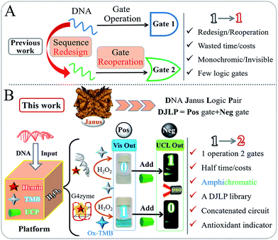
Since the first molecular AND logic gate was pioneered by Prof. de Silva in 1993,1 the field of molecular computing has flourished and made bioengineers think “outside-the-box”, leading to the development of various smart logical applications.2–11 As molecular level computers that use biomolecules as building blocks to perform Boolean logic,12–26 biocomputing has gained significant progress due to excellent biocompatibility, flexibility, and logical stringency.27–31 In recent decades, different biocomputing systems have been designed that rely on various substrates, such as enzymes, proteins, peptides, antibodies, and DNA.32–45 For instance, Katz et al. constructed a series of enzymatic logic devices by using the biocatalytic property of different natural enzymes.31 Fan et al. gained unique insights into DNA computing and made great progress in DNA tetrahedron/origami-based logic devices.43,44,48 Besides, the subtle bridging of different substrates (enzymes and DNA, antibodies and DNA, and so on) for innovative biocomputing has also been reported.32–34 Among these studies, DNA computing is considered as one of the most outstanding methods owing to its low-cost, predictable-design (Watson–Crick base pair), promising parallel-computing-ability and so on. Moreover, it is recognized that the multifunctional DNA logic systems could provide intelligent solutions for various bio-applications, such as logic-controlled biosensing/bio-diagnosis, drug load/release, genome editing, and stem-cell proliferation.46–51Despite great advancements, there are still significant drawbacks in this area. On one hand, the current DNA logic gates with different functions are always separately constructed according to their operating principles, as shown in Scheme 1A. The fussy/ineluctable sequences' redesign and gates' reconstruction cause the wastage of costs/time and low efficiency. On the other hand, the current DNA gates can only produce monochromic (colorimetric) or even invisible (electrochemical, fluorescent, or other) outputs, which largely limit their potential practicality. These drawbacks have been the “Achilles' heel” of this area. Considering the above background, exploring innovative multichromatic systems for operating a versatile DNA logic library in a facile and low-cost manner is urgently required.
In ancient Roman mythology, Janus is the god of beginnings and endings. It is known that he has two faces that could see the past and the future at the same time, as shown in Scheme 1B. Descending from this mythical concept, there are various such forms in various scientific areas, such as the anode/cathode of a battery, two complementary DNA strands, and hydrophilic/hydrophobic interfaces. Coincidently, for the logic gates, one characteristic point that researchers usually overlook is that they often coexist with corresponding gates of contrary functions. Herein, inspired by the mythical God Janus, we, for the first time, propose the concept of “DNA Janus Logic Pair” to classify the DNA logic gates with contrary functions into “Positive + Negative” gates (DJLP = Pos + Neg). For instance, the YES, AND, OR and INHIBIT gates are designated as the “Pos” gates, and the NOT, NAND, NOR and IMPLICATION gates with opposite functions belong to the “Neg” ones.
Subsequently, based on the peroxidase-like biocatalytic property of the G-quadruplex DNAzyme (G4zyme) and the luminescence quenching ability of oxidized 3,3′,5,5′-tetramethylbenzidine (OxTMB) towards the upconversion particles (UCP),52–59 we fabricated a universal amphichromatic platform (Scheme 1B) that kills two birds with one stone for operating a versatile DJLP library (YES + NOT, AND + NAND, OR + NOR, INHIBIT + IMPLICATION (INH + IMP), XOR + XNOR, Majority + Minority (MAJ + MIN), and so on). Different from the previous studies, the “Pos + Neg” gates of each DJLP were concomitantly achieved via the same one-time DNA reaction, which avoided the gates' redesign/reoperation and reduced the operation costs/time of the current DNA gates by at least half. Notably, both the amphichromatic outputs (Visual (Vis)-blue, UC luminescent (UCL)-green) were easily visualized by eyes under harmless-NIR (Scheme 1B), bringing greatly enhanced practicality to the method. Besides, the advanced logic devices (a parity checker for natural numbers 0–9, encoder/decoder) were also realized. Moreover, we constructed various concatenated logic circuits [(Pos-INH)/(Neg-INH)] via logically modulating the G4zyme's biocatalytic property with glutathione, thus enabling significantly improved computing complexity. Furthermore, taking the circuit “YES-INH-1-2 decoder” as the “computing core”, we designed an “antioxidant indicator” with ratiometric logical responses, which could recognize the presence of antioxidants intelligently.
Results and discussion
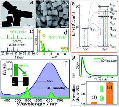
Scheme 1B illustrates the operating principle of the DJLP library. A mixture of hemin, TMB, UCP, and H2O2 was used as the universal “platform-box” and different DNAs acted as the inputs to selectively “open” the box. For the outputs of DJLP, pale-blue and dark-blue colors of Vis outputs were defined as the ‘‘0’’ and ‘‘1’’ states of the Pos gates, respectively. Pale-green and dark-green colors of the UCL outputs were defined as the ‘‘0’’ and ‘‘1’’ states of the Neg gates, respectively. If the non-G4 DNA was the input, the mixture of non-G4 DNA/hemin presented a weak catalytic ability towards the oxidation reaction between TMB and H2O2 due to the lack of G4zyme, thus producing a pale-blue colored solution. After mixing with the UCP solution, it did not influence the UC emission, which remained dark-green under NIR. This phenomenon matches the amphichromatic outputs “Vis = 0, UCL = 1”. On the other hand, if DNA that could form G4 was the input, the formed G4zyme catalyzed the oxidation of TMB, yielding a dark-blue colored OxTMB. After mixing with UCP, it quenched the UC emission (pale-green) efficiently, thus matching the amphichromatic outputs “Vis = 1, UCL = 0”.The UCP (β-NaYF4-doped) used in this DJLP library was synthesized according to previous reports.57–59 As shown in the TEM and SEM images (Fig. 1a and b), UCP (NaYF4: 18%Yb/2%Er) exhibited mono-disperse hexagonal structures, which was further identified by the well-matched XRD patterns (Fig. 1c). Moreover, the length of most of the UCP was about 0.7–0.8 μm (Fig. S1–S4†). For UC emission, Er-doped UCP (EDS in Fig. 1d) produced a clear green color (545 nm, 4S3/2 to 4I15/2 of Er3+, see mechanism in Fig. 1e) under a 980 nm NIR radiation, as shown in Fig. 1f. All of the above results proved the successful synthesis of UCP. After this, the reaction between UCP and OxTMB was explored. As shown in Fig. 1f, OxTMB showed absorption from 500 nm to 750 nm, exhibiting a broad overlap with the emission spectra of UCP, which provided the prerequisite for luminescence quenching. After mixing OxTMB with UCP, the green emission decreased remarkably with a quenching efficiency (QE) of 90.6%, which was calculated from the formula QE = (UCLb − UCLa)/UCLb × 100%, where UCLb and UCLa were the UCL peak intensities (545 nm) before and after adding OxTMB, respectively. For the quenching mechanism, the following observations were made: (1) the lifetimes (Fig. 1g) of UCP before (green line, 115.2 μs) and after adding OxTMB (blue line) were almost unchanged, proving that dynamic quenching was not the main reason;60,61 (2) after mixing with UCP, OxTMB's absorbance changed slightly (Fig. S5a†) and the reaction product that was catalyzed by non-G4 DNAs/hemin could not quench the UC emission (Fig. S5b†), thus eliminating the static quenching that was caused by the production of a non-fluorescent ground-state complex.60,61 Thus, we speculated that the luminescence quenching between UCP and OxTMB could be attributed to the inner filter effect, which was also consistent with other recent reports.60,61 To define the amphichromatic outputs more accurately, normalized Abs (650 nm) or UCL (545 nm) was used to discriminate the high/low outputs and 0.45 was taken as the universal threshold (Fig. 1h).
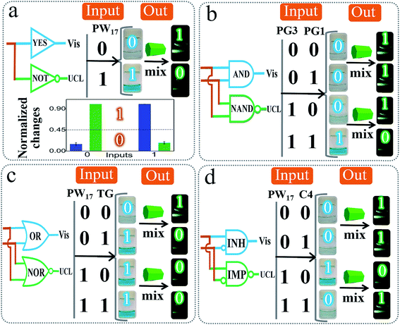
Based on the above design, we constructed various basic DJLPs initially. For the simplest “YES + NOT” pair (Fig. 2a), a complete G4 (PW17)62 was used as the input. Its operation was similar to the basic principle of the DJLP library that has been described above (Scheme 1B). The visual, UCL photos and column bars under different input variations featured the characteristics of the YES and NOT gates subtly, indicating its favorable performance. It should be noted that the concomitant operation of the YES and NOT gates in the “YES + NOT” pair can also work as a combinatorial circuit. This intuitive amphichromatic system brings enhanced flexibility and practicality. Analogously, the “AND + NAND” pair (Fig. 2b) (PG3 and PG1 that form G4 through hybridization were the inputs, Fig. S6†), the “OR + NOR” pair (Fig. 2c) (two G4 strands, PW17, and T30695 (TG)62 were the inputs), and the “INH + IMP” pair (Fig. 2d) (PW17 and its complementary DNA C4 were the inputs, and C4 was the inhibitory element, Fig. S6†) were also fabricated. The output column bars of these DJLPs under different input variations are given in Fig. S7,† indicating their successful operation. The sequences of DNAs used in this study are given in Table S1.†
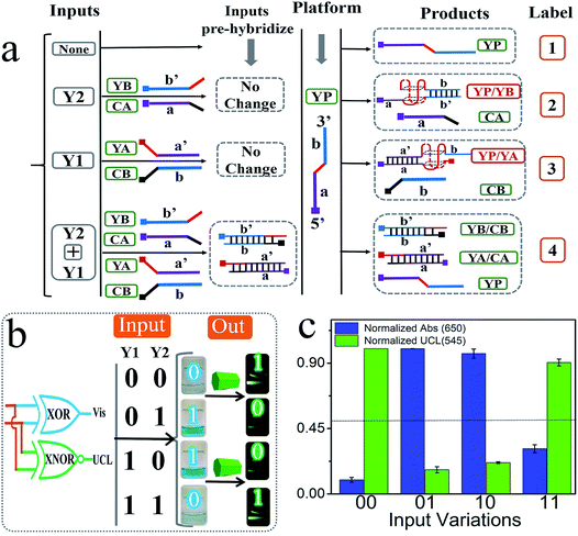
In addition to the above basic DJLPs, we also constructed the more complicated “XOR + XNOR” and “MAJ + MIN” DJLPs.54 The XOR and XNOR gates are the core elements in the half-adder/-subtractor, parity generator/checker,55 Feynman gate, etc. The detailed operation is illustrated as below: the strand YP that integrated with GGGTGGG in the middle part (red region) was the platform of the “XOR + XNOR” pair. The mixtures of the strands YA + CB and that of YB + CA were the inputs Y1 and Y2, respectively. As shown in Fig. 3a, the purple part (a′) of YA (with (TGGG)2 at the 5′ end, red region) could hybridize with the purple part of YP (a) to form the complete G4 (YP/YA). N-Methyl mesoporphyrin IX (NMM), the fluorescent dye that could exhibit high fluorescence after binding with G-quadruplex, was applied to confirm G4's formation. The significantly enhanced fluorescence intensity of NMM at 608 nm (Fig. S8a†) in the presence of YP and YA, and the corresponding circular dichorism (CD) peaks (Fig. S8b†) indicated the formation of parallel-G4.54 Analogously, strand YB can hybridize with the blue part (b) of YP to form the complete G4 (YP/YB), as shown in Fig. 3. By contrast, the purple part (a) of CA (with CCCA at the 3′ end, green region) could hybridize with YA to produce more stable YA/CA, indicating that the pre-hybridization between YA and CA inhibits the formation of G4 (YP/YA), as shown in Fig. S8c.† Similarly, the pre-hybridization between YB and CB will also inhibit the formation of G4 (YP/YB). On the other hand, the mixture of CB and YA (or the mixture of CA and YB) will influence neither the reaction between YP and YA (or YB) nor the formation of G4, as shown in Fig. 3. The PAGE verification can be found in our previous study.54 After reacting with the “platform-box”, the corresponding Vis and UCL outputs under different input states can be generated, as can be seen in Fig. 3c. The output columns matched the characteristics of the XOR and XNOR gates, indicating the successful operation of the “XOR + XNOR” DJLP.
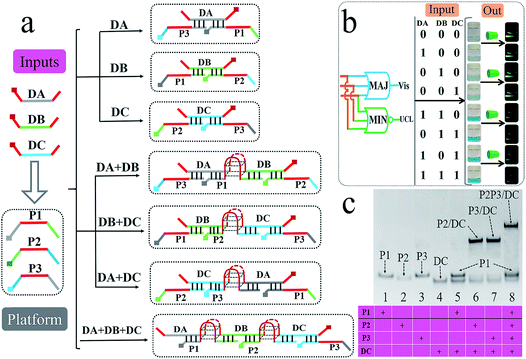
Till now, all of the above logic pairs are the 2-input DJLPs. To further demonstrate the universality of our amphichromatic platform, the 3-input “MAJ + MIN” DJLP that was composed of the MAJ (majority) and MIN (minority) gates was also fabricated. Both the MAJ and MIN gates play important roles in the full-adder, full-subtractor, molecular voter and other logic devices.57 For the operation of the “MAJ + MIN” DJLP, the middle region of the three platform DNAs (P1, P2, P3) were integrated with GGGTGGG, and the 3′ and 5′ ends of each input DNA (DA, DB, DC) were integrated with GGG. Through reasonable design, the right part of DC can hybridize with P3's left part (pale-blue region) and the left part of DC can complement with P2's right part (pale-blue region), while DC does not interact with P1. DA could bridge P1 and P3 together while not interacting with P2, and DB could bridge P1 and P2 together while not hybridizing with P3 (Fig. 4a). The DNA hybridizations were adequately verified by the corresponding PAGE results (Fig. 4c and S9†). Thus, the formation of G4 can be easily modulated by the above DNA hybridizations. With the addition of one input, no G4 will be produced. On the other hand, in the presence of two or more inputs, the complete G4 will form (Fig. 4a). After reacting with the universal amphichromatic platform, the corresponding amphichromatic outputs can be obtained, as seen in Fig. 4b. The output states under different input combinations feature the operation principle of the MAJ and MIN gates properly, indicating the satisfactory performance of the “MAJ + MIN” DJLP.
Apart from the different elementary logic gates, the advanced logic devices with specific functions are also widely used in semiconductor circuits. Herein, we further designed several advanced DNA logic devices based on our universal platform, including a parity checker18,19,57 that could discriminate the even/odd natural numbers (from 0 to 9), and 2-1 encoder/1-2 decoder20–24 that could also transform the binary code (data) into the data (code) for molecular information processing. The parity checker could identify the even/odd numbers among the natural numbers less than 10. Unlike the previous parity checkers, this one could generate even (Vis) and odd (UCL) types of outputs simultaneously. Initially, ten decimal numbers were transformed into the 4 bit binary-coded decimal (BCD) numbers,18,19 as shown in Fig. 5. Four strands, viz., T20, T30, T40, and PW17, were assigned as the corresponding 4 bit inputs. As shown in Fig. 5, only when the input combination corresponds to even decimal numbers (0, 2, 4, 6, 8) is, the Vis output will be “0”, which belongs to an even type parity checker. On the other hand, the UCL output will be “0” only when the input combination corresponds to the odd decimal numbers (1, 3, 5, 7, 9), which matches an odd type parity checker.
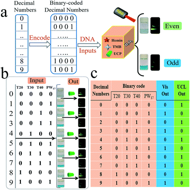 | ||
| Fig. 5 Operation of the parity-checker for discriminating natural numbers (from 0 to 9). For the parity checker, the strands T20, T30, T40, and PW17 were used as the 4 binary-coded inputs. | ||
For the encoder/decoder, it has been reported that an encoder can compress the information for transmission or even storage by transforming the data signal into a code and a decoder possesses the opposite functions.20–24 Herein, we constructed a 2-1 encoder and a 1-2 decoder, as shown in Fig. S10.† The 2-1 encoder could transform the 2-input bits into the 1-output code.20–24 The strands T30 and PW17 were applied as two inputs and the Vis signal was taken as the output. In the presence of T30 and the absence of PW17 (input “10”), the output will be “0” (pale-blue color) after reacting with the “platform-box”. In contrast, in the absence of T30 and in the presence of PW17 (input “01”), the output will be “1” (dark-blue color). This phenomenon matches the logical principle of a 2-1 encoder.20–24 Contrary to a 2-1 encoder, a 1-2 decoder could convert the 1-input code into 2-output signals. The strand PW17 was used as the input; in its absence and presence, the Vis and UCL output will be “0, 1” and “1, 0”, respectively. This input–output pattern corresponds to a 1-2 decoder.20–24
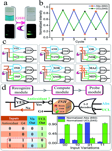
Semiconductor circuits can perform sophisticated logic computing via the integration of the elementary gates.1–11 Herein, we found that glutathione (GSH) could logically modulate the biocatalytic activity of G4zyme by utilizing its reduction ability (GSH + OxTMB = GSSG + TMB). As shown in Fig. 6a, after adding GSH into the mixture of UCPs/OxTMB, the color of OxTMB changed from dark-blue to colorless. Accordingly, the emission of UCP exhibited significant recovery. Besides, both the high/low Vis and UCL signals can be reversibly switched several times by alternatively adding GSH/OxTMB under the assistance of centrifugation (Fig. 6b). By utilizing the above phenomenon, a series of concatenated logic circuits (Fig. 6c) were further achieved, including (YES-INH)/(NOT-INH), (AND-INH)/(NAND-INH), (OR-INH)/(NOR-INH), (INH-INH)/(IMP-INH), (XOR-INH)/(XNOR-INH), and (MAJ-INH)/(MIN-INH), in which GSH was the inhibitory element. We presented the output column bars and the truth tables of (YES-INH)/(NOT-INH) and (AND-INH)/(NAND-INH) (Fig. S11 and 12†) as examples to demonstrate the effective operation of these concatenated circuits, which largely improved the computing complexity and also laid a solid foundation for more powerful biocomputing logic networks.
It is recognized that versatile logic systems can provide intelligent solutions to various bio-applications such as logic-programmed biosensing/bio-diagnosis.42–48,63 Antioxidants (such as GSH) play significant roles in many physiological functions such as helping to trap and neutralize the free radicals, thereby eliminating their harmful effects on the human body. The alternation in the level of antioxidants has been associated with many diseases, thus making the recognition of their absence/presence more significant. Based on the above platform and taking the circuit “YES-INH-1-2 decoder” as the “computing core”, we designed an “antioxidant indicator” with ratiometric logical responses, which could recognize the presence of antioxidants smartly. The first YES gate was used as the initial “Recognize module” to judge different targets (Yes for antioxidant and No for non-antioxidant). If an antioxidant was input, it was transferred to the second “Compute module”, the INHIBIT gate, another input of which was G4. The output of the INHIBIT gate is the mixture of G4 and GSH (the production of solely G4 is output “1”, while other products are “nothing”, and GSH and “GSH + G4” are output “0”). After reacting with the “platform-box”, the downstream “Probe module” (the 1-2 decoder,20–24 the output of the INH gate was used as the input and the Vis/UCL signals were the 2-output) will produce ratiometric Vis/UCL outputs and the corresponding truth table is shown in Fig. 6d. In the absence of antioxidants and in the presence of G4, it produces the output “Vis = 1, UCL = 0” (the threshold value was set as “0.45” to distinguish the high/low outputs). On the other hand, in the coexistence of the antioxidants and G4, OxTMB will be reduced to TMB that cannot quench the UC emission, generating the output “Vis = 0, UCL = 1”. Thus, the presence of antioxidants can be easily recognized. This ratiometric dual-output operating-mode brought strengthened reliability and intelligence to the bio-diagnosis. Fig. S13† presents the normalized ratiometric column values (Vis650/UCL545) in the presence of antioxidants (GSH, AA, and Cys as the model targets) and other reactants, and the significant differences indicated the excellent selectivity of this “antioxidant indicator”.
Conclusions
In summary, we, for the first time, proposed the concept of “DNA Janus Logic Pair” (DJLP) to classify DNA logic gates with contrary functions into “Positive + Negative” gates. Based on the biocatalytic property of G4zyme and the luminescence quenching phenomenon between OxTMB and upconversion particles, we constructed a universal amphichromatic platform that kills two birds with one stone by operating a versatile DJLP library. Various DJLPs, advanced logic devices (parity checker for distinguishing natural numbers less than 10, and encoder and decoder), the concatenated circuits and a logic-controlled “antioxidant indicator” were all successfully achieved. This study reduced the operating costs/time of the current DNA gates by at least half, and both the amphichromatic outputs (Visual-blue and UC luminescent-green) could be easily visualized by eyes under harmless-NIR, thus bringing largely enhanced computing complexity and practicality to the method. On combining with the genome editing technique, aptamers, nanozymes, DNA origami and other nanomaterials, numerous avenues for the development of more powerful biocomputing systems and intelligent logical bio-applications will open up.Experimental section
Chemicals
The DNAs were synthesized by Shanghai Sangon Biotechnology Co. (Shanghai, China) and the sequences are in Table S1.† They were all dissolved in distilled-water and quantified by UV-Vis spectroscopy. Glutathione (GSH) was provided by Shanghai Sangon Biotechnology Co. (Shanghai, China) and H2O2 (30%) was purchased from Beijing Xilong Chemical Industry (Beijing, China). Yb(NO3)3·5H2O (99.9%), Y(NO3)3·6H2O (99.9%), and Er(NO3)3·5H2O (99.9%) were provided by Aladdin (Shanghai, China). Sodium citrate and NaF were purchased from Beijing Chemical Works (Beijing, China). 3,3′,5,5′-tetramethylbenzidine (TMB) and hemin were provided by Sigma-Aldrich (USA). Hemin (2 mM) and TMB (0.5% (w/v)) were dissolved in DMSO to prepare the stock solution. The reaction buffers used in this study are: 1× HEPES buffer (25 mM HEPES, 20 mM KCl, 100 mM NaCl, 0.05% (w/v) Triton X-100, 1% (v/v) DMSO, pH 7.5) was used to incubate G4zyme. 1× MES-Ac buffer (25 mM MES, 20 mM KAc, pH 4.5) was used in the oxidation reaction of TMB.Synthesis of UCP
The green colored UCP were synthesized according to a previous report. In general, the mixture of Yb(NO3)3·5H2O, Y(NO3)3·6H2O, and Er(NO3)3·5H2O with different molar ratio (total concentration of the rare-earth element was 1 mmol) was added to 5 mL distilled water to achieve a homogeneous solution. Then, 8.5 mL of aqueous sodium citrate solution (3 g) was added and the above mixture was ultrasonicated for 15 min. After this, 16 mL NaF (0.52 g) was mixed with the above solution. After adding 1.5 mL 98% nitric acid to change the pH to 3, the mixture was stirred for another 40 min and added into a 50 mL Teflon autoclave. After reaction at 180 °C for about 2.5 h, the final solution was centrifuged and washed using ethanol and distilled water 6 times to obtain the white products. Finally, the UCP were dissolved in 20 mL distilled water as the stock solution (the concentrations of the UCP were 0.01475 g mL−1).SEM, TEM, XRD
TEM images of the UCP were obtained on a JEOL 2100F transmission electron microscope (TEM) (accelerating voltage = 200 kV) and the SEM images were taken on a Philips XL-30 ESEM (accelerating voltage = 20 kV). The XRD powder patterns were recorded on a D8 ADVANCE Wide Angle X-ray diffraction (BRUKER, Germany).Upconversion luminescence and UV-Vis spectra
The UCL spectra were collected from 400 to 750 nm on a Cary Eclipse Fluorescence Spectrophotometer (Agilent Technologies, USA) equipped with a 980 nm NIR-laser (Hi-Tech Optoelectronics Co., Ltd.). A constant working power was used for all the UCNPs samples and the emission slit width was 20 nm. The absorbance spectra of OxTMB were measured on a Cary 50 Scan UV/Vis/NIR Spectrophotometer (Varian, USA). The luminescence decay curves were obtained on a FLSP-920 Steady State and Time-resolved Fluorescence Spectrometer (Edinburgh, England).Native polyacrylamide gel electrophoresis (PAGE) and circular dichorism (CD)
The PAGE experiments were performed according to our previous studies. 1× TE buffer (50 mM Tris, 5 mM EDTA, and 50 mM MgCl2, pH 8.2) was used as the DNA hybridizing buffer and the 1× TBE buffer (18 mM Tris, 18 mM boric acid, and 1 mM EDTA, pH 8.02) was applied as the working buffer for PAGE. The CD spectra were obtained from 220 to 320 nm on a JASCO J-820 spectropolarimeter (Tokyo, Japan). The spectra were recorded in 1 mm path length cuvettes and averaged from three scans.Formation of G4zyme
The solutions of different DNAs were heated at 88 °C for 10 min and slowly cooled down to room temperature.(1) For the “YES + NOT”, “AND + NAND”, “OR + NOR”, “INH + IMP” DJLPs: 500 nM PW17 for “YES + NOT”; 500 nM PG3 and PG1 for “AND + NAND”; 500 nM PW17 and 500 nM TG for “OR + NOR” and 500 nM for PW17, 1 μM C4 for “INH + IMP” were selectively used and reacted at room temperature for about 10 min.
(2) For the “XOR + XNOR” DJLP, in the input combination of (00), 500 nM YP was used; in that of (01, 10), 500 nM YP was mixed with 500 nM YB, 1 μM CA (or 500 nM YA, 1 μM CB); in that of (11), 500 nM YB and 1 μM CA were premixed with 500 nM YA, 1 μM CB, and reacted at room temperature for about 10 min, and then 500 nM YP was added at last.
(3) For the “MAJ + MIN” DJLP, 400 nM DA, 300 nM DB, and 350 nM DC were alternatively added to the platform strands (mixture of 300 nM P1/P2/P3) and reacted at room temperature for about 10 min.
(4) For the parity-checker: 200 nM of T20, T30, T40, and 500 nM PW17 were selectively mixed and reacted at room temperature for about 10 min.
(5) For the 2-1 encoder, 1-2 decoder, different concatenated circuits (1 mM GSH was used), and the antioxidant-nose (200 μM, different targets or antioxidants), the concentrations of the DNAs were similar to the above devices.
After the above DNA reactions, equal volume of 1 μM hemin (DMSO) was added and the above mixture was incubated at room temperature for 1.5 h to form G4zyme.
The visual and UCL photos
20 μL 0.5% (w/v) TMB and 15 μL 30% (w/v) H2O2 was mixed with 30 μL of G4zyme and 935 μL 1× MES-Ac buffer in 1 mL centrifuge tube. After they reacted at room temperature for 10 min, a dark-blue colored OxTMB was obtained. Then, 1 mL OxTMB solution was mixed with 1 mL UCP (50 μL UCP in 950 μL 1× MES-Ac buffer). The visual photos were taken under natural light and the ones for UCL were taken under 980 nm NIR-laser (about 3.5 W for all the experiments) at dark. All the photos were taken using a digital Canon G12 camera.Conflicts of interest
There are no conflicts to declare.Acknowledgements
This work was supported by the National Natural Science Foundation of China (No. 21427811 and 21675151). Dr Daoqing Fan wishes to thank Dr Juan Wang for her long-lasting love and support.References
- A. P. de Silva, N. H. Q. Gunaratne and C. P. McCoy, Nature, 1993, 364, 42 CrossRef.
- A. P. De Silva and S. Uchiyama, Nat. Nanotechnol., 2007, 2, 399 CrossRef CAS PubMed.
- A. P. De Silva, H. N. Gunaratne, T. Gunnlaugsson, A. J. Huxley, C. P. McCoy, J. T. Rademacher and T. E. Rice, Chem. Rev., 1997, 97, 1515 CrossRef CAS PubMed.
- A. P. De Silva and N. D. McClenaghan, J. Am. Chem. Soc., 2000, 122, 3965 CrossRef CAS.
- A. P. de Silva, H. N. Gunaratne, J. L. Habib-Jiwan, C. P. McCoy, T. E. Rice and J. P. Soumillion, Angew. Chem., Int. Ed., 1995, 34, 1728 CrossRef.
- A. Credi, V. Balzani, S. J. Langford and J. F. Stoddart, J. Am. Chem. Soc., 1997, 119, 2679 CrossRef CAS.
- M. Amelia, M. Baroncini and A. Credi, Angew. Chem., Int. Ed., 2008, 47, 6240 CrossRef CAS PubMed.
- Y. Benenson, B. Gil, U. Ben-Dor, R. Adar and E. Shapiro, Nature, 2004, 429, 423 CrossRef CAS PubMed.
- E. Shapiro and B. Gil, Nat. Nanotechnol., 2007, 2, 84 CrossRef CAS PubMed.
- G. De Ruiter and M. E. Van Der Boom, Acc. Chem. Res., 2011, 44, 563 CrossRef CAS PubMed.
- V. Balzani, A. Credi and M. Venturi, ChemPhysChem, 2003, 4, 49 CrossRef CAS PubMed.
- L. Adleman, Science, 1994, 266, 1021 CrossRef CAS PubMed.
- L. Qian, E. Winfree and J. Bruck, Nature, 2011, 475, 368 CrossRef CAS PubMed.
- L. Qian and E. Winfree, Science, 2011, 332, 1196 CrossRef CAS PubMed.
- I. Willner, B. Shlyahovsky, M. Zayats and B. Willner, Chem. Soc. Rev., 2008, 37, 1153 RSC.
- R. Orbach, F. Remacle, R. Levine and I. Willner, Chem. Sci., 2014, 5, 1074 RSC.
- R. Orbach, F. Wang, O. Lioubashevski, R. Levine, F. Remacle and I. Willner, Chem. Sci., 2014, 5, 3381 RSC.
- K. He, Y. Li, B. Xiang, P. Zhao, Y. Hu, Y. Huang, W. Li, Z. Nie and S. Yao, Chem. Sci., 2015, 6, 3556 RSC.
- R.-R. Gao, S. Shi, Y. Zhu, H.-L. Huang and T.-M. Yao, Chem. Sci., 2016, 7, 1853 RSC.
- J. Andréasson, U. Pischel, S. D. Straight, T. A. Moore, A. L. Moore and D. Gust, J. Am. Chem. Soc., 2011, 133, 11641 CrossRef PubMed.
- P. Ceroni, G. Bergamini and V. Balzani, Angew. Chem., Int. Ed., 2009, 48, 8516 CrossRef CAS PubMed.
- D. Kang, R. J. White, F. Xia, X. Zuo, A. Vallée-Bélisle and K. W. Plaxco, NPG Asia Mater., 2012, 4, e1 CrossRef.
- J. Andréasson, S. D. Straight, T. A. Moore, A. L. Moore and D. Gust, J. Am. Chem. Soc., 2008, 130, 11122 CrossRef PubMed.
- D. Fan, J. Zhu, Y. Liu, E. Wang and S. Dong, Nanoscale, 2016, 8, 3834 RSC.
- J. Andreasson and U. Pischel, Chem. Soc. Rev., 2015, 44, 1053 RSC.
- J. Andreasson and U. Pischel, Chem. Soc. Rev., 2018, 47, 2266 RSC.
- S. Erbas-Cakmak, S. Kolemen, A. C. Sedgwick, T. Gunnlaugsson, T. D. James, J. Yoon and E. U. Akkaya, Chem. Soc. Rev., 2018, 47, 2228 RSC.
- M. N. Stojanovic, D. Stefanovic and S. Rudchenko, Acc. Chem. Res., 2014, 47, 1845 CrossRef CAS PubMed.
- M. N. Stojanovic and D. Stefanovic, Nat. Biotechnol., 2003, 21, 1069 CrossRef CAS PubMed.
- J. Elbaz, O. Lioubashevski, F. Wang, F. Remacle, R. D. Levine and I. Willner, Nat. Nanotechnol., 2010, 5, 417 CrossRef CAS PubMed.
- S. Mailloux, Y. V. Gerasimova, N. Guz, D. M. Kolpashchikov and E. Katz, Angew. Chem., Int. Ed., 2015, 54, 6562 CrossRef CAS PubMed.
- A. Prokup and A. Deiters, Angew. Chem., Int. Ed., 2014, 53, 13192 CrossRef CAS PubMed.
- Y. Li, S. Sun, L. Fan, S. Hu, Y. Huang, K. Zhang, Z. Nie and S. Yao, Angew. Chem., Int. Ed., 2017, 56, 14888 CAS.
- W. Engelen, L. H. Meijer, B. Somers, T. F. de Greef and M. Merkx, Nat. Commun., 2017, 8, 14473 CrossRef CAS PubMed.
- J. Andréasson and U. Pischel, Chem. Soc. Rev., 2010, 39, 174 Search PubMed.
- J. Zhao, A. R. Chandrasekaran, Q. Li, X. Li, R. Sha, N. C. Seeman and C. Mao, Angew. Chem., Int. Ed., 2015, 54, 9936 CrossRef CAS PubMed.
- M. R. Jones, N. C. Seeman and C. A. Mirkin, Science, 2015, 347, 1260901 CrossRef PubMed.
- K. M. Cherry and L. Qian, Nature, 2018, 559, 370 CrossRef CAS PubMed.
- G. Seelig, D. Soloveichik, D. Y. Zhang and E. Winfree, Science, 2006, 314, 1585 CrossRef CAS PubMed.
- W. Meng, R. A. Muscat, M. L. McKee, P. J. Milnes, A. H. El-Sagheer, J. Bath, B. G. Davis, T. Brown, R. K. O'Reilly and A. J. Turberfield, Nat. Chem., 2016, 8, 542 CAS.
- Y. V. Gerasimova and D. M. Kolpashchikov, Angew. Chem., Int. Ed., 2016, 55, 10244 CAS.
- D. Fan, Y. Fan, E. Wang and S. Dong, Chem. Sci., 2018, 9, 6981 RSC.
- J. Li, A. A. Green, H. Yan and C. Fan, Nat. Chem., 2017, 9, 1056 CAS.
- X. Qu, S. Wang, Z. Ge, J. Wang, G. Yao, J. Li, X. Zuo, J. Shi, S. Song, L. Wang, L. Li, H. Pei and C. Fan, J. Am. Chem. Soc., 2017, 139, 10176 CAS.
- A. J. Thubagere, W. Li, R. F. Johnson, Z. Chen, S. Doroudi, Y. L. Lee, G. Izatt, S. Wittman, N. Srinivas, D. Woods, E. Winfree and L. Qian, Science, 2017, 357, 1112 CAS.
- Q. Yuan, Y. Wu, J. Wang, D. Lu, Z. Zhao, T. Liu, X. Zhang and W. Tan, Angew. Chem., Int. Ed., 2013, 52, 13965 CrossRef CAS PubMed.
- R. Peng, X. Zheng, Y. Lyu, L. Xu, X. Zhang, G. Ke, Q. Liu, C. You, S. Huan and W. Tan, J. Am. Chem. Soc., 2018, 140, 9793 CrossRef CAS PubMed.
- X. Li, X. Xie, Z. Ma, Q. Li, L. Liu, X. Hu, C. Liu, B. Li, H. Wang, N. Chen, C. Fan and H. Song, Adv. Mater., 2018, 30, e1804861 CrossRef PubMed.
- S. M. Douglas, I. Bachelet and G. M. Church, Science, 2012, 335, 831 CrossRef CAS PubMed.
- C. Yan, Z. Guo, Y. Liu, P. Shi, H. Tian and W. H. Zhu, Chem. Sci., 2018, 9, 6176 RSC.
- D. M. Kolpashchikov, J. Am. Chem. Soc., 2008, 130, 2934 CrossRef CAS PubMed.
- M. Centola, J. Valero and M. Famulok, J. Am. Chem. Soc., 2017, 139, 16044 CrossRef CAS PubMed.
- J. Chen, S. Zhou and J. Wen, Angew. Chem., Int. Ed., 2015, 54, 446 CAS.
- D. Fan, E. Wang and S. Dong, Mater. Horiz., 2017, 4, 924 RSC.
- D. Fan, E. Wang and S. Dong, Chem. Sci., 2017, 8, 1888 RSC.
- L. Liang, Y. Liu, C. Bu, K. Guo, W. Sun, N. Huang, T. Peng, B. Sebo, M. Pan, W. Liu, S. Guo and X. Z. Zhao, Adv. Mater., 2013, 25, 2174 CrossRef CAS PubMed.
- D. Fan, E. Wang and S. Dong, Mater. Horiz., 2019, 6, 375 RSC.
- F. Wang and X. Liu, Chem. Soc. Rev., 2009, 38, 976 RSC.
- X. Zhu, Q. Su, W. Feng and F. Li, Chem. Soc. Rev., 2017, 46, 10259 Search PubMed.
- J. Sun, J. Zhao, L. Wang, H. Li, F. Yang and X. Yang, ACS Sens., 2018, 3, 183 CrossRef CAS PubMed.
- Y. Liu, Q. Ouyang, H. Li, Z. Zhang and Q. Chen, ACS Appl. Mater. Interfaces, 2017, 9, 18314 CrossRef CAS PubMed.
- T. Li, E. Wang and S. Dong, J. Am. Chem. Soc., 2009, 131, 15082 CrossRef CAS PubMed.
- S. W. Oh, A. Pereira, T. Zhang, T. Li, A. Lane and J. Fu, Angew. Chem., Int. Ed., 2018, 57, 13086 CrossRef CAS PubMed.
Footnotes |
| † Electronic supplementary information (ESI) available. See DOI: 10.1039/c9sc01865d |
| ‡ These authors contributed equally. |
| This journal is © The Royal Society of Chemistry 2019 |

