DOI:
10.1039/C9SC01374A
(Edge Article)
Chem. Sci., 2019,
10, 5308-5318
Crystal-facet-dependent denitrosylation: modulation of NO release from S-nitrosothiols by Cu2O polymorphs†
Received
20th March 2019
, Accepted 24th April 2019
First published on 24th April 2019
Abstract
Nitric oxide (NO), a gaseous small molecule generated by the nitric oxide synthase (NOS) enzymes, plays key roles in signal transduction. The thiol groups present in many proteins and small molecules undergo nitrosylation to form the corresponding S-nitrosothiols. The release of NO from S-nitrosothiols is a key strategy to maintain the NO levels in biological systems. However, the controlled release of NO from the nitrosylated compounds at physiological pH remains a challenge. In this paper, we describe the synthesis and NO releasing ability of Cu2O nanomaterials and provide the first experimental evidence that the nanocrystals having different crystal facets within the same crystal system exhibit different activities toward S-nitrosothiols. We used various imaging techniques and time-dependent spectroscopic measurements to understand the nature of catalytically active species involved in the surface reactions. The denitrosylation reactions by Cu2O can be carried out multiple times without affecting the catalytic activity.
Introduction
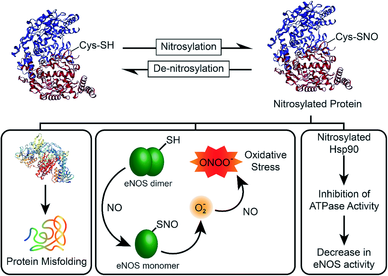
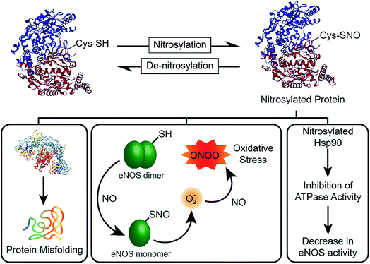
In 1998, the Nobel Prize was awarded to Robert F. Furchgott, Louis J. Ignarro and Ferid Murad “for their discoveries concerning nitric oxide as a signalling molecule in the cardiovascular system”.1 Their research had shown that nitric oxide (NO), a transient free radical with a half-life of ∼5 s, is involved in transmitting cellular signals in mammals. Now, it is well known that NO is involved in a variety of important biological processes such as a signalling molecule in the nervous system, vasodilator in the cardiovascular system, and it is used as a key molecule by the immune system to fight against infections.2 However, the imbalance between the nitrosylation and denitrosylation activities of enzymes affect the NO concentration (Fig. 1), which ultimately results in the formation of nitrosylated proteins via a covalent binding of NO to the cysteine residues of proteins.3 The nitrosylation of proteins leads to various deleterious effects, which include the monomerization of functionally active endothelial nitric oxide synthase (eNOS), leading to the production of superoxide species that can react with NO to generate the highly toxic peroxynitrite (ONOO−) and elevation of oxidative stress in the cells.4 It has been shown that nitrosylated Hsp90 inhibits the ATPase activity, which leads to the decrease in the eNOS activity (Fig. 1).5 As NO is synthesized in endothelial cells by eNOS, the low level of NO due to impairment of the enzyme activity affects the endothelial function. On the other hand, elevated levels of NO cause nitrosative stress related signalling, leading to post-translational modification of many proteins, neurotoxicity and apoptosis.6 NO concentration above 1.0 μM results in nitrosative stress and necrotic cell death by generating a large amount of reactive nitrogen species (RNS). Therefore, the biological effects of NO are highly dependent on its concentration.6
 |
| | Fig. 1 Chemical biology of nitric oxide (NO). The nitrosylation/denitrosylation reactions play important role in the maintenance of NO levels in the mammalian cells. An excessive nitrosylation can lead to protein misfolding, oxidative stress and impairment of NO synthesis by the nitric oxide synthase (NOS) enzymes. | |
Synthetic compounds such as organic nitrates (RONO2) and nitrites (RONO), metal nitrosyl complexes, N-nitrosamines (RN(NO)R′), S-nitrosothiols (RSNO) have been used to generate NO for biological applications.7S-nitrosothiols (RSNOs) such as S-nitrosoalbumin, S-nitroso-N-acetyl-penicillamine (SNAP), and S-nitrosoglutathione (GSNO) have been used extensively for storage and release of NO.8 As several diseases such as asthma, cystic fibrosis, Parkinson's disease, heart failure, and stroke are associated with dysregulated S-nitrosylation, regulating the NO levels is crucial for the maintenance of normal physiology.6 In biological systems, the removal of NO from nitrosylated proteins and small molecules is mediated by denitrosylases enzymes, which maintain the NO homeostasis and dynamically regulate the cellular signal transduction.6 To date, two physiologically relevant enzymatic denitrosylating systems have been demonstrated, which include the thioredoxin (Trx)/thioredoxin reductase (TrxR) and the glutathione (GSH)/GSNO reductase (GSNOR) systems.6g,h A few selenium-based compounds, transition metal (Cu and Fe) complexes, metal–organic frameworks, polymers and nanomaterials have been reported to mediate the release of NO from S-nitrosothiols (RSNO).9 However, the controlled release of NO from S-nitrosylated compounds at physiological pH remains a challenge. Recently, Schoenfisch and co-workers developed polyurethanes and cyclodextrins-based compounds for NO release.7c,d On the other hand, Meyerhoff and co-workers used a polymer doped with SNAP for storage and release of NO.7e,f In this paper, we report the synthesis and NO releasing activity of Cu2O nanocrystals10a,b and show, for the first time, that nanocrystal polymorphs having different crystal facets10 within the same crystal system exhibit different activity toward S-nitrosothiols. We also describe the nature of catalytically active species involved in the surface reactions using various time-dependent spectroscopic studies.
Results and discussion
Synthesis and characterization of Cu2O nanocrystals
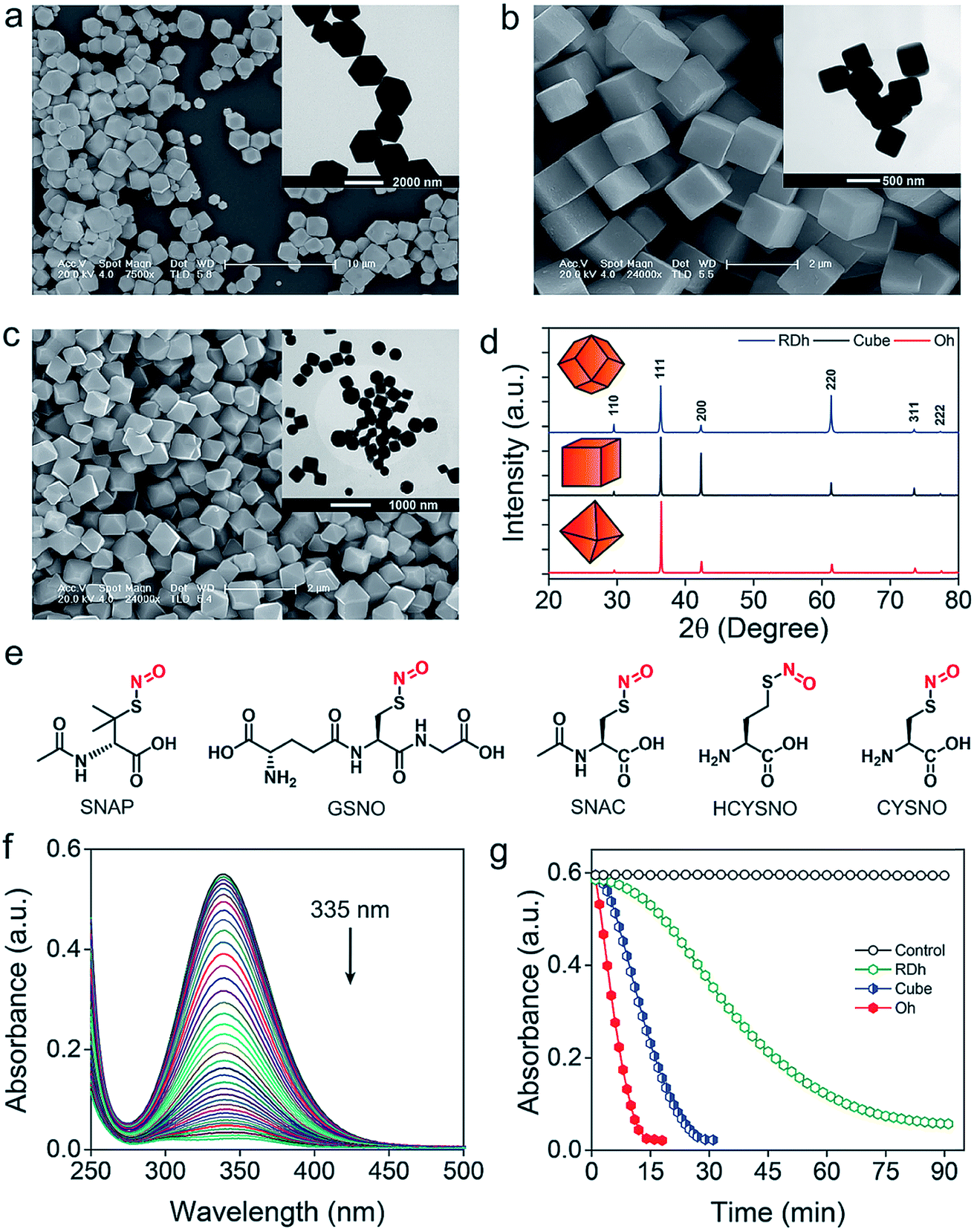
Three different morphologies of Cu2O nanomaterials – rhombic dodecahedra (RDh), cube, and octahedra (Oh) were synthesized using either copper(II) chloride (cube and Oh) or copper(II) sulfate (RDh) under reducing conditions.11 All the morphologies were thoroughly characterized by scanning electron microscopy (SEM) and transmission electron microscopy (TEM), which confirmed the distinguishable differences between the nanomaterials (Fig. 2a–c). To understand the crystalline nature of the materials, powder X-ray diffraction (PXRD) measurements were carried out and the diffraction peaks were well indexed to the standard cubic fcc Cu2O structure (JCPDS = 78-2076, a = b = c = 4.267 Å and α = β = γ = 90°) (Fig. 2d).11 The two strong peaks (110) and (220) in RDh indicate the presence of {110} facets in this material. Similarly, the strong (200) and (111) peaks confirm the presence of {100} and {111} facets in cube and Oh, respectively. The EDS spectrum of all the morphologies and X-ray mapping of Oh confirmed the presence and distribution of copper (Cu) and oxygen (O) atoms in all materials (Fig. S1 and S2†). X-ray photoelectron spectroscopy (XPS) analysis was performed to determine the oxidation state of the metal ions in the materials. The binding energies (BE) and the difference in the BE between the Cu 2p3/2 and Cu 2p1/2 peaks (∼19.8 eV) confirm that copper exists in +1 oxidation state in all the morphologies (Fig. S5, Table S4†).10b,17 To gain insight into the bonding connectivity between the copper and oxygen atoms in the fcc Cu2O nanomaterials, FT-IR and FT-Raman spectra were recorded (Fig. S3, S4 and Table S3†). In the Raman spectra, an intense peak observed at 219 cm−1 can be assigned to the 2nd order overtone of Cu2O; corresponding to 2Γ(12)− mode.17c,d The peak observed at 635 cm−1 in the FT-IR is ascribed to the stretching vibration of Cu2–O.17c The well-defined sharp peaks at 219 cm−1 (FT-Raman) and 635 cm−1 (FT-IR) demonstrate the high structural quality of the synthesized materials, which correlates well with the X-ray diffraction results (Fig. 2d).
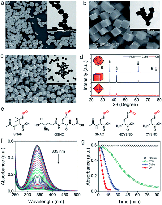 |
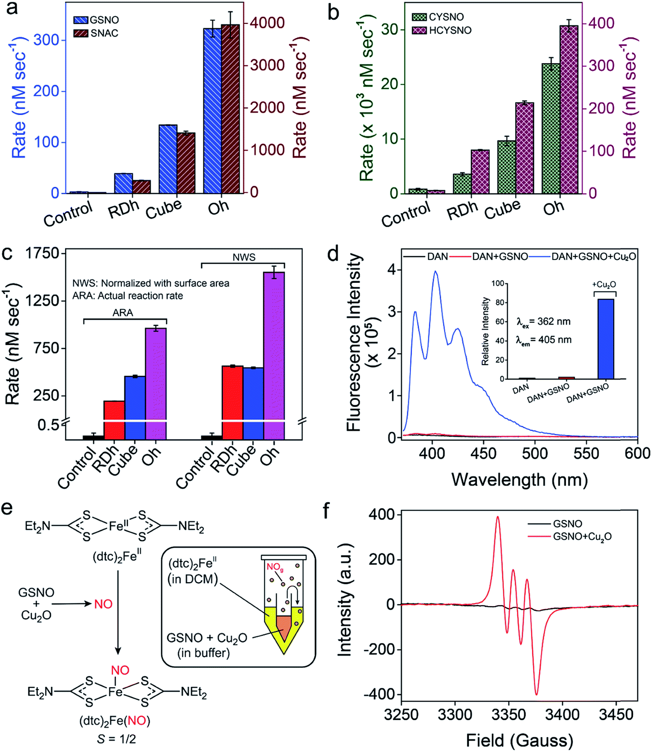
| | Fig. 2 (a–c) SEM and TEM (inset) images of RDh, cube and Oh, respectively. (d) PXRD pattern of fcc cubic Cu2O materials. (e) Chemical structure of S-nitrosothiols used as substrates for the release of nitric oxide. (f) Denitrosylation of SNAP by RDh. The decrease in the absorbance of SNAP (500 μM) was monitored up to 90 min with time interval of 2 min by UV-Vis spectrophotometer in presence of RDh (2 ng μL−1). (g) Denitrosylation of SNAP by three different Cu2O nanomaterials. The decrease in the absorbance of SNAP was monitored at 335 nm by UV-Vis spectrophotometer. Assay condition: SNAP (500 μM), Cu2O (2 ng μL−1), 0.1 M sodium phosphate buffer (pH 7.4), 25 °C. | |
Denitrosylation of S-nitrosothiols by Cu2O nanocrystals
The denitrosylation of S-nitrosothiols (RSNO) by Cu2O nanocrystals was monitored spectrophotometrically by following the decrease in the absorbance of RSNO at 335 nm over time (Fig. 2f).15 As S-nitrosothiols are sensitive to light and heat, it is important to store all the samples in dark at low temperatures (−20 °C) to avoid any decomposition. As shown in Fig. 2g, all three materials were found to be efficient in the denitrosylation of SNAP. The rate of the reactions was determined by using the molar extinction coefficient of respective RSNO at 335 nm as shown in the ESI (Fig. 2e and Table S1†). A comparison of the activities of the nanomaterials with SNAP indicates that Oh exhibited the highest activity in the series and the rate of denitrosylation observed for this material was found to be almost five- and two-fold higher than that of RDh and cube, respectively (Fig. 3c). A similar trend was observed with other S-nitrosothiols – GSNO, SNAC, CYSNO and HCYSNO (Fig. 3a and b, S6 and Table S2†). These observations clearly indicate that the denitrosylation of RSNO by Cu2O nanomaterials is morphology-dependent. Interestingly, the rate of denitrosylation of RSNO is not directly proportional to the surface area of the materials (Fig. 3c and S8†). The surface area, pore diameter and pore volume measured by the Brunauer–Emmett–Teller (BET) method (Fig. S7†) indicate that cube with the higher surface area (5.4 m2 g−1) than that of Oh (3.2 m2 g−1) exhibits an almost 3-fold lower activity after normalization with respect to surface area as compared to that of the Oh nanocrystals.
 |
| | Fig. 3 (a and b) A comparison of the rate of denitrosylation by three different Cu2O nanomaterials. (c) The actual rates of denitrosylation of SNAP (500 μM) in the presence 2 ng μL−1 of Cu2O and a comparison with the rates obtained by normalizing the concentration with respect to 10 mm2 of the surface area. Assay conditions: 0.1 M sodium phosphate buffer (pH 7.4) at 25 °C. (d) Detection of NO by a fluorescence assay using DAN (5 μM). (e) The reaction of (dtc)2Fe with NO generated from the reaction of GSNO with Cu2O. (f) Room temperature electron paramagnetic resonance (EPR) spectra of [(dtc)2FeNO] complex. | |
Confirmation of the NO release at physiological pH
To confirm the release of NO from RSNO by Cu2O nanomaterials, various spectroscopic (UV-Vis, fluorescence and EPR) methods were developed. For the fluorescence-based detection of NO, 2,3-diaminonaphthalene (DAN) assay was used.18 Briefly, a smaller vial containing Cu2O nanomaterials (50 ng μL−1 in 0.1 M phosphate buffer pH 7.4) was placed inside a larger vial containing DAN (1.0 mM in DMSO) solution such that the two solutions do not mix with each other. The larger tube was then sealed (Fig. S9†) and a solution of GSNO (20 mM) was injected into the smaller vial having the Cu2O nanomaterials. The in situ generated NO from the smaller vial diffuses into the larger vial and reacts with DAN to produce 2,3-naphthotriazole (NATH), which is weakly fluorescent, but it exhibits strong fluorescence in basic medium due to the formation of 2,3-naphthotriazole anion (NAT).18 The excitation and emission wavelengths used for the experiments were 362 and 405 nm, respectively. When the denitrosylation was carried out without catalysts, no significant fluorescence was observed, confirming that the release of NO is mediated by the Cu2O nanomaterials (Fig. 3d and S10†). Further, the amount of NO released during the denitrosylation was also quantified using the DAN-based fluorescence assay. These experiments confirmed that the amount of NO produced in the Cu2O-mediated denitrosylation corresponds well with the decrease in the concentration of S-nitrosothiols as shown for GSNO (Fig. S11†).
The release of NO was also confirmed by electron paramagnetic resonance (EPR) spectroscopy using a similar experimental set-up. For this purpose, (dtc)2Fe complex was used for trapping the NO released from GSNO to produce the EPR active (dtc)2FeNO (Fig. 3e). The room temperature EPR spectrum shows three lines (S = 1/2) at g = 2.01 with A (14N) = 13.0 G, which is characteristic of (dtc)2FeNO complex.16b The very weak EPR signal observed for GSNO in the absence of nanomaterials indicate that the release of NO from GSNO is very slow and it leads to the formation of only minor amount of (dtc)2FeNO complex under identical experimental conditions (Fig. 3f and Table S5†). We also used an UV-Vis spectroscopy technique in which the formation of a nitrosyl complex (TPP)CoNO from (TPP)CoII was monitored. The red shift of Q-band from 527 nm to 535 nm indicated the formation the nitrosyl complex and no shift of Q-band was observed in the absence of Cu2O nanomaterials.16b The presence of Co-bound nitric oxide (TPP)CoNO complex was further confirmed by FT-IR spectroscopy. The peak at 1696 cm−1 corresponds to N![[double bond, length as m-dash]](https://www.rsc.org/images/entities/char_e001.gif) O stretching vibration of (TPP)CoNO,19 which is absent in the native metal complex i.e. (TPP)CoII (Fig. S12†). In addition to the spectroscopic techniques mentioned above, we also used the ferrocene-encapsulated (2-hydroxypropyl)-β-cyclodextrin (β-HCD-Fc) to observe the release of NO by a visual colour change (yellow to blue) of the solution due to the formation of β-HCD-Fc+ (reaction with NO and β-HCD-Fc).14 The characteristic band at 618 nm observed in the UV-Vis spectrum confirms the formation of β-HCD-Fc+ (Fig. S13†).
O stretching vibration of (TPP)CoNO,19 which is absent in the native metal complex i.e. (TPP)CoII (Fig. S12†). In addition to the spectroscopic techniques mentioned above, we also used the ferrocene-encapsulated (2-hydroxypropyl)-β-cyclodextrin (β-HCD-Fc) to observe the release of NO by a visual colour change (yellow to blue) of the solution due to the formation of β-HCD-Fc+ (reaction with NO and β-HCD-Fc).14 The characteristic band at 618 nm observed in the UV-Vis spectrum confirms the formation of β-HCD-Fc+ (Fig. S13†).
Formation of glutathione disulfide (GSSG) in the denitrosylation of GSNO
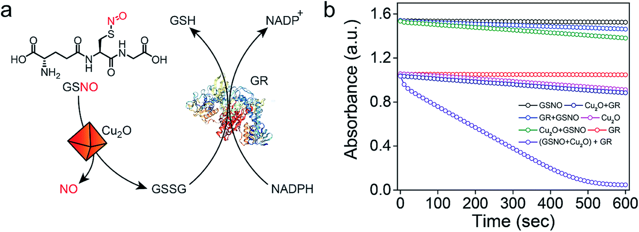
Earlier reports suggested that copper-mediated denitrosylation of RSNO results in the formation of disulfide (RSSR) along with the release of NO.9f,15 To understand whether the release of NO from GSNO is accompanied with the formation of glutathione disulfide (GSSG), we established a coupled assay in which the formation of GSSG can be confirmed by using the enzyme glutathione reductase (GR) (Fig. 4a). In mammalian cells, GR catalyzes the reduction of the disulfide bond in GSSG using NADPH as co-factor to generate GSH, which is important to maintain the cellular redox homeostasis.20 After incubating GSNO and Cu2O for 45 min, the activity of GR was monitored by measuring the decrease in the absorbance of NADPH at 340 nm. A rapid decrease in the absorption of NADPH was observed, indicating that the reaction of GSNO with Cu2O indeed generates GSSG in addition to NO. Although the generation of NO from GSNO by Cu2O is accompanied by the oxidation of Cu(I) to Cu(II) and the formation of GS−, the highly reactive GS− undergoes oxidation by Cu(II) to produce GSSG. When the experiments were carried out in the absence of Cu2O, no significant decrease in the absorbance of NADPH was observed. Other control experiments revealed that NADPH or GR in the presence of NADPH do not mediate any significant denitrosylation of GSNO (Fig. 4b and S14†).
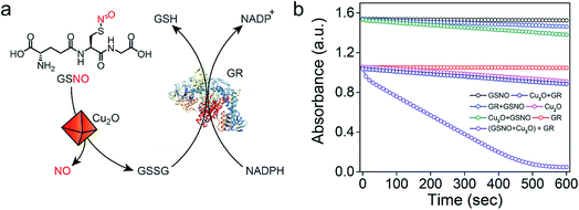 |
| | Fig. 4 (a) A coupled assay system involving glutathione reductase (GR) and NADPH to confirm the formation of GSSG. (b) Monitoring the decrease in the absorbance of NADPH at 340 nm under various conditions. | |
Mechanistic investigations of the denitrosylation reactions
Analysis of the exposed crystal-facets on the Cu2O surface
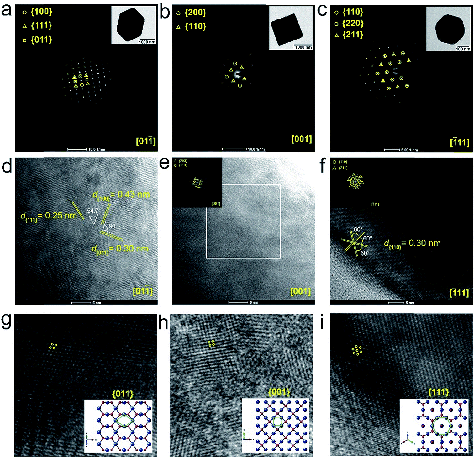
The difference in the initial rates observed for the denitrosylation of RSNO by Cu2O having different morphologies indicate that the denitrosylase activity is morphology-dependent and activity follows the order RDh < cube < Oh. Surprisingly, no correlation was observed between the activity and the surface area of the materials (Fig. 3c), indicating that the arrangement or orientation of the atoms on exposed facets of the material surface may be responsible for the remarkable difference in the denitrosylation activity of Cu2O nanomaterials having various morphologies. To understand the growth direction and exposed facets in the materials, we analyzed the selected area electron diffraction (SAED) patterns, high resolution TEM (HRTEM) images and their FFT (Fast-Fourier-Transform) patterns of the materials.10 The inter-planer spacing and the angles between the planes observed in the HRTEM images and the spots in SAED and FFT patterns were well indexed in accordance with the crystal structure of fcc cubic Cu2O. The analysis revealed that the surface of the three morphologies, RDh, cube and Oh, consists of {011}, {001} and {111} facets, respectively (Fig. 5, S15 and S16†).
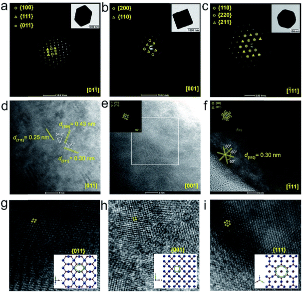 |
| | Fig. 5 (a–c) The selected area electron diffraction (SAED) pattern of RDh, cube and Oh respectively. (d and e) The HRTEM of RDh, cube and Oh, respectively. The fast-Fourier-transform patterns for the cube and Oh are shown as insets. (g–i) Zoomed HRTEM images of RDh, cube and Oh, respectively. The arrangement corresponding to the crystal facets {011} for RDh, {001} for cube and {111} for Oh are given as insets. | |
The role of surface properties in the denitrosylation activity
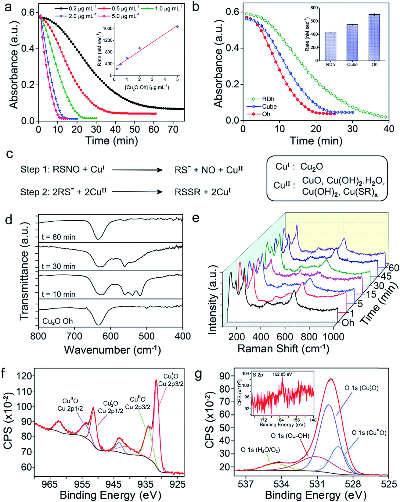
To understand the effect of catalyst concentration in the denitrosylation of RSNO, we have monitored the reaction of SNAP using the Oh polymorph at various concentrations. It was observed that the rate of denitrosylation increased linearly with an increase in the concentration of nanomaterial, indicating that the number of copper atoms plays an important role in the denitrosylation activity (Fig. 6a). As discussed in the previous sections, the activity of Oh was found to be almost three times higher than that of RDh or cube when the catalyst concentrations were normalized with respect to the surface area (Fig. 3c). Even when the concentration of the catalysts was normalized with respect to the number of copper atoms present on the surface of the nanomaterials (Tables 1, S6 and S7†), the activity of Oh was found to be almost 1.5- and 1.2-fold higher than that of RDh and cube, respectively (Fig. 6b). These observations indicate that the {111} crystal facet present in Oh is more reactive than the {011} and {001} facets present in RDh and cube, respectively. To understand the remarkably high reactivity of the {111} surface in Oh, we carried out isothermal titration calorimetry (ITC) experiment using GSH as a model substrate to find out the thermodynamic parameters for the surface of the nanomaterial (Fig. S22†). These experiments revealed that the dissociation constant of GSH (Kd) for the {111} surface is much lower than that of the {011} facet, indicating a stronger binding of GSH to the surface with {111} facets as compared to that with the {011} facets. The difference in the surface charge (zeta-potential, ζ) of the nanomaterials possibly leads to the change in the binding affinity of RSNO towards Cu2O surfaces (Tables 1 and S21†).21
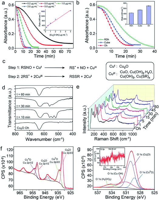 |
| | Fig. 6 (a) Effect of Cu2O Oh concentration on the denitrosylation of SNAP. (b) A comparison of the denitrosylation activity of RDh, cube and Oh after normalizing with the number of copper atoms on the surface. (c) Mechanism of Cu2O-mediated NO release from RSNO, involving a redox cycle between Cu(I) and Cu(II) species. (d) Time-dependent FT-IR spectra and (e) time-dependent FT-Raman spectra of the nanomaterials during the denitrosylation of SNAP by Cu2O Oh. (f and g) Short-range XPS spectra of Cu 2p and O 1s, respectively, recorded on the materials recovered after the catalysis. The inset in (g) indicates the sulfur 2p peak in XPS. | |
Table 1 The surface area, total number of copper atoms, surface charge (zeta-potential) and the dissociation constants (Kd) for GSH obtained for the three nanomaterialsa
| Crystal-Facet on nanomaterials surface |
Surface areab |
Number of copper atoms on surface (×1013) |
Surface charge (mV) |
Dissociation constantcKd (μM) |
|
d = edge length of single unit.
For a single unit.
From isothermal titration calorimetry.
|
| {011} – RDh |
8√2d2 |
1.00 |
−10.9 |
69.3 |
| {001} – cube |
6d2 |
1.89 |
6.6 |
37.4 |
| {111} – Oh |
2√3d2 |
4.83 |
24.0 |
19.2 |
Probing the intermediates in the catalysis by spectroscopy
Several spectroscopic studies were performed to understand the nature of intermediates formed on the surface during the catalysis. The time-dependent FT-IR spectroscopic experiments for the reaction of SNAP with Cu2O Oh indicated that the peak at 635 cm−1 corresponding to the Cu(I)–O vibration became broader and the characteristic peaks for Cu(II)–O vibrations appeared at 518, 539 and 565 cm−1 after 10 min of reaction time (Fig. 6d), which indicated the existence of mixed phases i.e. Cu2O and CuO during the catalysis.17c,22 The peaks below 600 cm−1 started disappearing with time and after 60 min, only a sharp peak at 635 cm−1 along with an additional peak for CuO at 565 cm−1 were observed (Fig. 6d). Similar experimental results were also observed by time-dependent FT-Raman spectroscopy. The peak around 630 cm−1 corresponding to the Cu(I)–O stretching vibration became broader after 15 min, indicating the presence of both Cu(I) and Cu(II) oxide. The characteristic Raman spectral peak for CuII(OH)2 was detected at 470 cm−1 after 15 min along with two other broad peaks at 291 cm−1 and 630 cm−1.17c,d The formation of CuIIO was identified after 30 min of catalysis by observing the peak at 265 cm−1, which disappeared over the time. After 60 min, the peaks mainly corresponding to the vibrations of Cu(I)–O were observed (Fig. 6e).17c,d To further understand the nature of chemical species formed on the surface of the nanomaterials, XPS of copper (Cu 2p) and oxygen (O 1s) were recorded after the catalysis. The shake-up satellite peaks observed for copper confirms the presence of Cu(II) species along with Cu(I) on the surface of the nanomaterials.17,23 Similarly, the deconvoluted O 1s spectra showed peaks corresponding to Cu(II)- and Cu(I)-oxide along with a peak for copper hydroxide (Cu–OH).17,23 The small peak at 162.9 eV observed in the XPS of sulphur can be ascribed to the presence of trace amount of copper-bound thiolate (Cu(SR)x) as an intermediate (Fig. 6f and g).16b,24 The weak signals for sulfur bound to the material was also observed in the X-ray mapping images obtained after the catalysis (Fig. S20†).25
Analysis of the surface after catalysis by PXRD, SEM and TEM
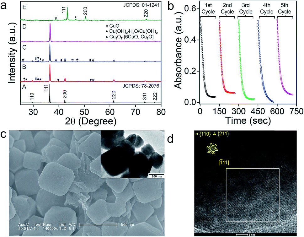
The intermediate phases of catalyst on the surface of nanomaterials were identified by studying the PXRD of the nanomaterials recovered after the catalysis (Fig. 7a). In addition to the most intense peaks of Cu2O, a few smaller peaks corresponding to CuII(OH)2·H2O, CuII(OH)2 and CuIIO species were identified on the surface of the catalyst (Fig. 7a). The minor peaks for the Cu(II) species disappeared after treatment of the catalyst with 6.0 mM ascorbic acid (D in Fig. 7a). When the concentration of ascorbic acid was increased further to 0.6 M, a complete reduction of the nanomaterials to elemental copper (Cu) was observed (JCPDS: 01-1241 as shown in E in Fig. 7a). These results correlate well with the proposed mechanism of NO release from RSNO involving the initial oxidation of Cu(I) to Cu(II),15b,c which can be reduced back to Cu(I) by the thiolates (RS−) produced in the first step of the denitrosylation reaction (Fig. 6c–g). Warren and co-workers studied the reactivity of copper(II) thiolates towards S-nitrosothiols and proposed a pathway for the generation of NO within the coordination sphere of copper model complexes.24b,c However, the facile redox changes between the Cu(I) and Cu(II) in Cu2O is further confirmed by carrying out the denitrosylation reactions using the materials recovered from the first cycle. In fact, the nanomaterials can mediate multiple cycles of the denitrosylation reactions without loss of the catalytic activity (Fig. 7b and S19†). The SEM and TEM images for Oh on materials recovered from the reaction mixture after the catalysis indicated that their morphology and surface remain unaltered, suggesting that the nanomaterials are quite stable under the reaction conditions (Fig. 7c). The HRTEM images of the materials recorded after multiple reactions cycles indicate that the exposed facets present on the surfaces of material were also unaffected (Fig. 7d).
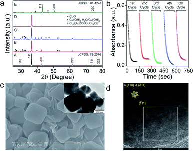 |
| | Fig. 7 (a) PXRD study of Cu2O Oh after the catalysis. A: parent Cu2O Oh, B: catalyst recovered after 60 min, C: catalyst recovered after 60 min and heated at 60 °C for 12 h, D: treated with 6.0 mM of ascorbic acid after heating, E: treated with 0.6 M ascorbic acid after heating. (b) Experiments demonstrating the recyclability of Cu2O Oh (0.2 ng μL−1) using five cycles of 1.0 mM CYSNO in 0.1 M phosphate buffer (pH 7.4) at 25 °C. (c) SEM and TEM (inset) images of Oh after the catalysis. (d) HRTEM and corresponding FFT (inset) of Oh after the catalysis. | |
Conclusions
We demonstrated in this paper that Cu2O-based nanomaterials can release NO from S-nitrosothiols and the catalytic activity is morphology-dependent. This study provides the first experimental evidence that the denitrosylating activity of Cu2O nanocrystals can be altered by changing the crystal facets within the same crystal system. Surprisingly, no direct correlation between the activity and the surface area of the materials was observed. The different arrangement of the atoms on the surface is found to be responsible for the remarkable change in the denitrosylation activity of Cu2O nanomaterials having various morphologies. A detailed mechanistic investigation revealed that the higher activity of the Cu2O nanomaterial having Oh morphology as compared to that of RDh and cube is due to the presence of the {111} crystal facet in Oh, which is more efficient than the {011} and {001} facets present in RDh and cube, respectively, in the denitrosylation of S-nitrosothiols. Further, the Cu2O Oh nanocrystals having {111} facets may be employed for a quick release of NO, whereas the RDh morphology having the {011} facets will be useful for a slow and sustained release of NO. Therefore, the facet-dependent denitrosylation activity described in this paper may find potential applications in modulating the NO bioavailability under disease conditions where the physiological NO signaling is severely impaired. For example, the decrease in the NO levels in endothelial cells is known to cause endothelial dysfunction, leading to several vascular diseases. The materials that can improve the levels of NO in these cells are likely to be potential candidates for the treatment of vascular disorders.
Experimental section
Synthesis of Cu2O cubes and Cu2O octahedra
CuCl2·2H2O (341 mg) and PVP (for cubes: 0 g, for octahedra: 17.8 g) were dissolved in 200 mL of ultrapure water.11 The solution was heated to 55 °C and 20 mL of 2 M NaOH solution was added to the solution under constant stirring. After 30 min, 20 mL of 0.6 M ascorbic acid solution was added to the reaction mixture dropwise and the resultant solution was stirred at 55 °C for 5 h (for cubes) or 3 h (for octahedra). After cooling the reaction mixture to 25 °C, brick coloured nanomaterials were obtained by centrifugation of the reaction mixture at 9000 rpm for 10 min, followed by washing with ultrapure water and absolute ethanol. Finally, the nanomaterials were dried in oven at 50 °C for 24 h.
Synthesis of Cu2O rhombic dodecahedra
CuSO4·10H2O (1 g), dissolved in 160 mL of ultrapure water, was treated with 16 mL of oleic acid and 80 mL of absolute ethanol under vigorous stirring.11 After the reaction mixture was heated to 100 °C under constant stirring, 40 mL of 0.8 M NaOH solution was added dropwise. After stirring the mixture for 5 min, D-glucose solution (13.68 g dissolved in 120 mL of ultrapure water) was added and stirring was continued for 2 h. The nanomaterials were obtained by centrifugation of the reaction mixture at 9000 rpm for 10 min, followed by washing with ultrapure water and absolute ethanol. Finally, the nanomaterials were dried in oven at 50 °C for 24 h.
Synthesis of S-nitrosoglutathione (GSNO) and other RSNO
S-nitrosthiols were synthesised by following the literature method.12 Glutathione (GSH, 100 mg, 0.325 mmol), dissolved in 383 μL of ultrapure water, was treated with 38 μL of concentrated hydrochloric acid. The solution was stirred in an ice bath (0–4 °C). The pH of the solution was maintained between 1 and 2. After the complete dissolution of GSH, 23 mg (0.325 mmol) of sodium nitrite was added in dark. The colour of the solution turned red immediately. After stirring the reaction for additional 10 min, the red coloured solution was aliquoted in Eppendorf tubes and stored at −80 °C.
Other S-nitrosothiols, CYSNO, HCYSNO and SNAC were synthesised by following a similar procedure using L-cysteine, L-homocysteine and L-N-acetylcysteine (NAC), respectively.
Synthesis of bis(N,N-diethyldithiocarbamato)iron(II) ((dtc)2FeII) complex
The title compound was synthesized following a reported procedure with minor modifications.13 Briefly, FeSO4·7H2O (217 mg, 0.78 mmol) and diethylammonium diethyldithiocarbamate (347 mg, 1.56 mmol) were added in dichloromethane (10 mL) and the reaction mixture was stirred for 8 h. The resultant brown solution was filtered, and the brown filtrate was dried under reduced pressure to obtain (dtc)2FeII as a brown solid, which was then recrystallized in diethyl ether to get pure (dtc)2FeII.
Synthesis of β-HCD-Fc
To a 10 mM solution of ferrocene (Fc) (50 mL) in dichloromethane, 10 mM aqueous solution of (2-hydroxypropyl)-β-cyclodextrin (β-HCD) (50 mL) was added and the mixture was stirred at 45 °C under reflux for 24 h. The aqueous fraction from the reaction mixture containing ferrocene entrapped in β-HCD complex (β-HCD-Fc) was collected.14 The synthesis was repeated several times, the aqueous fractions were collected, and the combined solution was freeze-dried to get a concentrated solution (yellow) of β-HCD-Fc, which was used for the detection of nitric oxide.
Measurement of denitrosylation of RSNO by nanomaterials
The denitrosylation of S-nitrosothiols (RSNO) by three different Cu2O nanomaterials was monitored by UV-Vis spectrophotometer.15b The decrease in the absorbance of RSNO (at 335 nm) was monitored under time-drive mode to quantify the rate of catalysis by the nanozymes. The assay conditions for different RSNO is given in the ESI (Table S2†).
Trapping of nitric oxide by (TPP)CoII complex
An experimental set-up was designed for the detection of NO using (TPP)CoII complex.16 A small vial (0.75 mL) containing GSNO (20 mM in 0.1 M phosphate buffer, pH 7.4) and Cu2O nanomaterials (50 ng μL−1) were placed inside a large vial (5 mL) containing 1.0 mM (TPP)CoII in dichloromethane (DCM). The solutions were kept undisturbed for 45 min. It was observed that the nitric oxide gas to generated from GSNO diffused into the dichloromethane solution and reacted with (TPP)CoII to form (TPP)CoNO complex. The UV-Vis spectrum of the DCM solution confirmed the formation of (TPP)CoNO complex from the red shift of the Q-band from 527 nm to 535 nm. Two control experiments were performed. In one case, the experiment was performed in the absence of Cu2O nanomaterials in the assay buffer and in another case, the experiment was carried out in the absence of both Cu2O nanomaterials and GSNO. The UV-Vis spectra of the DCM solution from the control experiments showed no shift in the Q-band. Similar experiments were carried out using other S-nitrosothiols (HCYSNO and SNAC) as nitric oxide source and the formation of (TPP)CoNO complex was confirmed by UV-Vis and FT-IR spectroscopic experiments.
Time-dependent FT-Raman and FT-IR spectroscopy
The catalysis was performed using Cu2O Oh as the model catalyst and SNAP as substrate in 0.1 M sodium phosphate buffer (pH 7.4) at 25 °C. After each time point, the catalyst was recovered from the reaction mixture by centrifugation and washed with acetone several times. The recovered catalyst was used for the spectroscopic studies. FT-Raman spectroscopy was performed on Renishaw in-Via Raman Microscope (Renishaw Inc, UK) by using an excitation wavelength of 514 nm, 50× L objective lens, 10 s exposure and 3 accumulations (power < 10 mW). The FT-IR spectra were recorded on Perkin Elmer instrument using KBr pellet made with the nanomaterial recovered from the reaction mixture.
Isothermal titration calorimetry (ITC)
The stock solution of the catalyst (2 mg mL−1) was prepared by dispersing it in isopropyl alcohol (IPA) and the stock solution of GSH was prepared in 0.1 M sodium phosphate buffer pH 7.4. ITC experiments were performed using Microcal VP-ITC at 25 °C. The catalyst (10 ng μL−1) were dispersed in ultrapure water and loaded onto the sample cell. The ligand solution (GSH, 1.0 mM), loaded in the injection syringe, was titrated into the sample cell as a series of injections (aliquots of 10 μL) separated by 4 min interval with constant stirring at 307 RPM. Control titrations with the ligand into water in the sample cell and water titrated with catalyst in the sample cell were carried out to confirm that the heat of dilution was negligible. The data were fitted with Microcal Origin 5 software. After subtraction of the respective controls from the main titration profile, the binding constant (Ka) and enthalpy (ΔH) were obtained by fitting the titration curves to a one-site binding model. The dissociation constant (Kd) values were calculated from 1/Ka.
Conflicts of interest
The authors declare no competing financial interest.
Acknowledgements
This study was supported by the Science and Engineering Research Board (SERB, EMR/IISc-01/2016) and Nano Mission (SR/NM/NS-1380/2014), Department of Science and Technology (DST), New Delhi. S. G. and P. R. acknowledge the Indian Institute of Science, Bangalore, for a research fellowship. S. G. thanks Mr Estak Ahmed and Arnab for helping in EPR spectroscopy with X-band JEOL (JES FA200) instrument. The authors thank Prof. S. Umapathy and Prof. P. Thilagar for providing Raman spectroscopy and UV-Vis spectroscopy facilities, respectively. We also thank the AFMM Facility and CeNSE, IISc for the spectroscopic and microscopic facilities. S. G. thanks Aparna for helping in ITC experiment. G. M. acknowledges the SERB/DST for the award of J. C. Bose National Fellowship (SB/S2/JCB-067/2015).
Notes and references
- The Nobel Prize in Physiology or Medicine 1998, https://www.nobelprize.org.
-
(a) S. Moncada, R. M. Palmer and E. A. Higgs, Pharmacol. Rev., 1991, 43, 109–142 CAS;
(b) K. Matsushita, C. N. Morrell, B. Cambien, S. X. Yang, M. Yamakuchi, C. Bao, M. R. Hara, R. A. Quick, W. Cao, B. O'Rourke, J. M. Lowenstein, J. Pevsner, D. D. Wagner and C. J. Lowenstein, Cell, 2003, 115, 139–150 CrossRef CAS PubMed;
(c) S. P. L. Cary, J. A. Winger, E. R. Derbyshire and M. A. Marletta, Trends Biochem. Sci., 2006, 31, 231–239 CrossRef CAS PubMed;
(d) C. Coletta, A. Papapetropoulos, K. Erdelyi, G. Olah, K. Módis, P. Panopoulos, A. Simakopoulou, D. Gerö, I. Sharina, E. Martin and C. Szabo, Proc. Natl. Acad. Sci. U. S. A., 2012, 109, 9161–9166 CrossRef CAS PubMed;
(e) M. Eberhardt, M. Dux, B. Namer, J. Miljkovic, N. Cordasic, C. Will, T. I. Kichko, J. de la Roche, M. Fischer, S. A. Suárez, D. Bikiel, K. Dorsch, A. Leffler, A. Babes, A. Lampert, J. K. Lennerz, J. Jacobi, M. A. Martí, F. Doctorovich, E. D. Högestätt, P. M. Zygmunt, I. Ivanovic-Burmazovic, K. Messlinger, P. Reeh and M. R. Filipovic, Nat. Commun., 2014, 5, 4381 CrossRef CAS PubMed.
-
(a) D. T. Hess, A. Matsumoto, S. O. Kim, H. E. Marshall and J. S. Stamler, Nat. Rev. Mol. Cell Biol., 2005, 6, 150–166 CrossRef CAS PubMed;
(b) I. Gusarov and E. Nudler, Mol. Cell, 2018, 69, 351–353 CrossRef CAS PubMed.
-
(a) K. Ravi, L. A. Brennan, S. Levic, P. A. Ross and S. M. Black, Proc. Natl. Acad. Sci. U. S. A., 2004, 101, 2619–2624 CrossRef CAS PubMed;
(b) C. A. Chen, T. Y. Wang, S. Varadharaj, L. A. Reyes, C. Hemann, M. A. Talukder, Y. R. Chen, L. J. Druhan and J. L. Zweier, Nature, 2010, 468, 1115–1118 CrossRef CAS PubMed.
- A. M. Ruiz, L. Villanueva, C. G. Orduña, D. L. Ferrer, M. A. Higueras, C. Tarín, I. R. Crespo, J. Vázquez and S. Lamas, Proc. Natl. Acad. Sci. U. S. A., 2005, 102, 8525–8530 CrossRef PubMed.
-
(a) S. A. Lipton, Y. B. Choi, Z. H. Pan, S. Z. Lei, H. S. V. Chen, N. J. Sucher, J. Loscalzo, D. J. Singel and J. S. Stamler, Nature, 1993, 364, 626–632 CrossRef CAS PubMed;
(b) G. Melino, F. Bernassola, R. A. Knight, M. T. Corasaniti, G. Nistic and A. Finazzi-Agro, Nature, 1997, 388, 432–433 CrossRef CAS PubMed;
(c) C. Bogdan, Nat. Immunol., 2001, 2, 907–916 CrossRef CAS PubMed;
(d) P. Vallance and J. Leiper, Nat. Rev. Drug Discovery, 2002, 1, 939–950 CrossRef CAS PubMed;
(e)
A. R. Butler and R. Nicholson, Life, Death and Nitric Oxide, Royal Society of Chemistry, Cambridge, 2003 Search PubMed;
(f) D. D. Thomas, L. A. Ridnour, J. S. Isenberg, W. Flores-Santana, C. H. Switzer, S. Donzellie, P. Hussain, C. Vecoli, N. Paolocci, S. Ambs, C. Colton, C. Harris, D. D. Roberts and D. A. Wink, Free Radical Biol. Med., 2008, 45, 18–31 CrossRef CAS PubMed;
(g) B. Limaa, M. T. Forrester, D. T. Hess and J. S. Stamler, Circ. Res., 2010, 106, 633–646 CrossRef PubMed;
(h) M. Benhar, M. T. Forrester and J. S. Stamler, Nat. Rev. Mol. Cell Biol., 2009, 10, 721–732 CrossRef CAS PubMed;
(i) R. Sengupta and A. Holmgren, Antioxid. Redox Signaling, 2013, 18, 259–269 CrossRef CAS PubMed.
-
(a) P. G. Wang, M. Xian, X. Tang, X. Wu, Z. Wen, T. Cai and J. A. Jaczuk, Chem. Rev., 2002, 102, 1091–1134 CrossRef CAS PubMed;
(b) L. J. Ignarro, C. Napoli and J. Loscalzo, Circ. Res., 2002, 90, 21–28 CrossRef CAS PubMed;
(c) M. J. Malone-Povolny and M. H. Schoenfisch, ACS Appl. Mater. Interfaces, 2019, 11, 12216–12223 CrossRef CAS PubMed;
(d) H. Jin, L. Yang, M. J. R. Ahonen and M. H. Schoenfisch, J. Am. Chem. Soc., 2018, 140, 14178–14184 CrossRef CAS PubMed;
(e) Y. Wo, Z. Li, E. J. Brisbois, A. Colletta, J. Wu, T. C. Major, C. Xi, R. H. Bartlett, A. J. Matzger and M. E. Meyerhoff, ACS Appl. Mater. Interfaces, 2015, 7, 22218–22227 CrossRef CAS PubMed;
(f) H. Ren, J. Wu, C. Xi, N. Lehnert, T. Major, R. H. Bartlett and M. E. Meyerhoff, ACS Appl. Mater. Interfaces, 2014, 6, 3779–3783 CrossRef CAS PubMed.
-
(a) J. S. Stamler, O. Jaraki, J. Osborne, D. I. Simon, J. Keaney, J. Vita, D. Singel, C. R. Valeri and J. Loscalzo, Proc. Natl. Acad. Sci. U. S. A., 1992, 89, 7664–7667 CrossRef;
(b) B. Gaston, J. Reilly, J. M. Drazen, J. Fackler, P. Ramdev, D. Arnelle, M. E. Mullins, D. J. Sugarbaker, C. Chee, D. J. Singel, J. Loscalzo and J. S. Stamler, Proc. Natl. Acad. Sci. U. S. A., 1993, 90, 10957–10961 CrossRef CAS PubMed;
(c) L. Jia, C. Bonaventura, J. Bonaventura and J. S. Stamler, Nature, 1996, 380, 221–226 CrossRef CAS PubMed.
-
(a) B. K. Oh and M. E. Meyerhoff, J. Am. Chem. Soc., 2003, 125, 9552–9553 CrossRef CAS PubMed;
(b) J. L. Harding and M. M. Reynolds, J. Am. Chem. Soc., 2012, 134, 3330–3333 CrossRef CAS PubMed;
(c) P. Taladriz-Blanco, V. Pastoriza-Santos, J. Pérez-Juste and P. Hervés, Langmuir, 2013, 29, 8061–8069 CrossRef CAS PubMed;
(d) L. Tan, A. Wan and H. Li, ACS Appl. Mater. Interfaces, 2013, 5, 11163–11171 CrossRef CAS PubMed;
(e) C. W. McCarthy, R. J. Guillory, J. Goldman and M. C. Frost, ACS Appl. Mater. Interfaces, 2016, 8, 10128–10135 CrossRef CAS PubMed;
(f) J. Pant, M. J. Goudie, S. P. Hopkins, E. J. Brisbois and H. Handa, ACS Appl. Mater. Interfaces, 2017, 9, 15254–15264 CrossRef CAS PubMed;
(g) B. Qu, L. Yuan, J. Li, J. Wang, H. Lv and X. Yang, J. Mater. Chem. B, 2019, 7, 150–156 RSC.
-
(a) C. H. Kuo, Y. C. Yang, S. Gwo and M. H. Huang, J. Am. Chem. Soc., 2011, 133, 1052–1057 CrossRef CAS PubMed;
(b) K. Chanda, S. Rej and M. H. Huang, Chem.–Eur. J., 2013, 19, 16036–16043 CrossRef CAS PubMed;
(c) C. Ge, G. Fang, X. Shen, Y. Chong, W. G. Wamer, X. Gao, Z. Chai, C. Chen and J. J. Yin, ACS Nano, 2016, 10, 10436–10445 CrossRef CAS PubMed;
(d) K. Khulbe, P. Roy, A. Radhakrishnan and G. Mugesh, ChemCatChem, 2018, 10, 4840–4845 CrossRef CAS;
(e) S. Ghosh, P. Roy, N. Karmodak, E. D. Jemmis and G. Mugesh, Angew. Chem., Int. Ed., 2018, 130, 4600–4605 CrossRef.
- Q. Hua, K. Chen, S. Chang, Y. Ma and W. Huang, J. Phys. Chem. C, 2011, 115, 20618–20627 CrossRef CAS.
- T. W. Hart, Tetrahedron Lett., 1985, 26, 2013–2016 CrossRef CAS.
-
(a) L. H. Pignolet, R. A. Lewis and R. H. Holm, J. Am. Chem. Soc., 1971, 93, 360–371 CrossRef;
(b) A. J. P. Cardenas, R. Abelman and T. H. Warren, Chem. Commun., 2014, 50, 168–170 RSC.
- S. Priya, T. Kaviyarasana and S. Berchmans, Analyst, 2012, 137, 1541–1543 RSC.
-
(a) R. J. Singh, N. Hogg, J. Joseph and B. Kalyanaraman, J. Biol. Chem., 1996, 271, 18596–18603 CrossRef CAS PubMed;
(b) A. P. Dicks, H. R. Swift, D. L. H. Williams, A. R. Butler, H. H. Al-Sadoni and B. B. Cox, J. Chem. Soc., Perkin Trans. 2, 1996, 481–487 RSC;
(c) D. L. H. Williams, Acc. Chem. Res., 1999, 32, 869–876 CrossRef CAS;
(d) G. Stubauer, A. Giuffrè and P. Sarti, J. Biol. Chem., 1999, 274, 28128–28133 CrossRef CAS PubMed.
-
(a) B. C. Sanders, S. M. Hassan and T. C. Harrop, J. Am. Chem. Soc., 2014, 136, 10230–10233 CrossRef CAS PubMed;
(b) S. Kundu, W. Y. Kim, J. A. Bertke and T. H. Warren, J. Am. Chem. Soc., 2017, 139, 1045–1048 CrossRef CAS PubMed.
-
(a) S. Poulston, P. M. Parlett, P. Stone and M. Bowker, Surf. Interface Anal., 1996, 24, 811–820 CrossRef CAS;
(b) M. C. Biesinger, L. W. M. Laua, A. R. Gerson and R. C. Smart, Appl. Surf. Sci., 2010, 257, 887–898 CrossRef CAS;
(c) A. Sahai, N. Goswami, S. D. Kaushik and S. Tripathi, Appl. Surf. Sci., 2016, 390, 974–983 CrossRef CAS;
(d) Y. Deng, A. D. Handoko, Y. Du, S. Xi and B. S. Yeo, ACS Catal., 2016, 6, 2473–2481 CrossRef CAS.
- R. Esquembre, I. Pastor, R. Mallavia and C. R. Mateo, J. Photochem. Photobiol., A, 2005, 173, 384–389 CrossRef CAS.
-
(a) A. Efraty, R. Bystrek, J. A. Geaman, S. S. Sandhu, M. H. A. Huang and R. H. Herber, Inorg. Chem., 1974, 13, 1269–1272 CrossRef CAS;
(b)
Nitrosyl complexes in inorganic chemistry, biochemistry and medicine II, ed. D. M. P. Mingos, Springer-Verlag, Heidelberg, 2014 Search PubMed.
-
(a) V. I. Lushchak, J. Amino Acids, 2012, 736837 Search PubMed;
(b) N. Couto, J. Wood and J. Barber, Free Radical Biol. Med., 2016, 95, 27–42 CrossRef CAS PubMed.
- W. C. J. Ho, Q. Tay, H. Qi, Z. Huang, J. Li and Z. Chen, Molecules, 2017, 22, 677 CrossRef PubMed.
-
(a) A. H. Jareeze, J. Kufa Phys., 2014, 6, 36–41 Search PubMed;
(b) V. Gopinath, S. Priyadarshini, A. R. Al-Maleki, M. Alagiri, R. Yahya, S. Saravan and J. Vadivelu, RSC Adv., 2016, 6, 110986–110995 RSC.
-
(a) J. S. Shaikh, R. C. Pawar, R. S. Devan, Y. R. Ma, P. P. Salvi, S. S. Kolekar and P. S. Patil, Electrochim. Acta, 2011, 56, 2127–2134 CrossRef CAS;
(b) J. P. Kim, E. S. Pak, T. E. Hong, J. S. Bae, M. G. Ha, J. S. Jin, E. D. Jeong and K. S. Hong, J. Ceram. Process. Res., 2012, 13, s96–s99 Search PubMed.
-
(a) Y. Ju-Nam, Y. S. Chen, J. J. Ojeda, D. W. Allen, N. A. Cross, P. H. E. Gardiner and N. Bricklebank, RSC Adv., 2012, 2, 10345–10351 RSC;
(b) S. Zhang, N. Çelebi-Ölçüm, M. M. Melzer, K. N. Houk and T. H. Warren, J. Am. Chem. Soc., 2013, 135, 16746–16749 CrossRef CAS PubMed;
(c) S. Zhang, M. M. Melzer, S. N. Sen, N. Çelebi-Ölçüm and T. H. Warren, Nat. Chem., 2016, 8, 663–669 CrossRef CAS PubMed.
- A. A. Vernekar, D. Sinha, S. Srivastava, P. U. Paramasivam, P. D'Silva and G. Mugesh, Nat. Commun., 2014, 5, 5301 CrossRef CAS PubMed.
Footnote |
| † Electronic supplementary information (ESI) available. See DOI: 10.1039/c9sc01374a |
|
| This journal is © The Royal Society of Chemistry 2019 |
Click here to see how this site uses Cookies. View our privacy policy here. 
 Open Access Article
 This Open Access Article is licensed under a Creative Commons Attribution-Non Commercial 3.0 Unported Licence
 *
*