 Open Access Article
Rapid room temperature synthesis of red iridium(III) complexes containing a four-membered Ir–S–C–S chelating ring for highly efficient OLEDs with EQE over 30%†
Guang-Zhao
Lu‡
a,
Ning
Su‡
a,
Hui-Qing
Yang
a,
Qi
Zhu
b,
Wen-Wei
Zhang
 a,
You-Xuan
Zheng
 *a,
Liang
Zhou
 *b,
Jing-Lin
Zuo
 *a,
Zhao-Xu
Chen
 *a and
Hong-Jie
Zhang
 b
b
aState Key Laboratory of Coordination Chemistry, Jiangsu Key Laboratory of Advanced Organic Materials, Collaborative Innovation Center of Advanced Microstructures, School of Chemistry and Chemical Engineering, Nanjing University, Nanjing 210093, P. R. China. E-mail: yxzheng@nju.edu.cn; zuojl@nju.edu.cn; zxchen@nju.edu.cn
bState Key Laboratory of Rare Earth Resource Utilization, Changchun Institute of Applied Chemistry, Chinese Academy of Sciences, Changchun 130022, P. R. China. E-mail: zhoul@ciac.ac.cn
First published on 11th February 2019
Abstract
Three red cyclometalated iridium(III) complexes (4tfmpq)2Ir(dipdtc), (4tfmpq)2Ir(dpdtc) and (4tfmpq)2Ir(Czdtc) (4tfmpq = 4-(4-(trifluoromethyl)phenyl)quinazoline, dipdtc = N,N-diisopropyl dithiocarbamate, dpdtc = N,N-diphenyl dithiocarbamate, and Czdtc = N-carbazolyl dithiocarbamate) containing the unique four-membered Ir–S–C–S backbone ring were synthesized in five minutes at room temperature with good yields, and the Gibbs free energy calculation results indicate that all reactions are exothermic and thermodynamically favorable processes. The emission colors (λpeak = 641–611 nm), photoluminescence quantum efficiencies (ΦP = 58.3–93.0%) and bipolar properties can be effectively regulated by introducing different electron-donating substituents into the dithiocarbamate ancillary ligands. Employing these emitters, organic light emitting diodes (OLEDs) with double emissive layers exhibit excellent performances with a maximum brightness over 60![[thin space (1/6-em)]](https://www.rsc.org/images/entities/char_2009.gif) 000 cd m−2, a maximum current efficiency of 40.68 cd A−1, a maximum external quantum efficiency (EQEmax) of 30.54%, and an EQE of 26.79% at the practical luminance of 1000 cd m−2. These results demonstrate that Ir(III) complexes with sulfur-containing ligands can be rapidly synthesized at room temperature, which is key to the production of metal luminescent materials for large-scale application in highly efficient OLEDs.
000 cd m−2, a maximum current efficiency of 40.68 cd A−1, a maximum external quantum efficiency (EQEmax) of 30.54%, and an EQE of 26.79% at the practical luminance of 1000 cd m−2. These results demonstrate that Ir(III) complexes with sulfur-containing ligands can be rapidly synthesized at room temperature, which is key to the production of metal luminescent materials for large-scale application in highly efficient OLEDs.
Introduction
Highly efficient phosphorescent cyclometalated complexes have been widely employed to fabricate organic light-emitting diodes (OLEDs) because of their unique optoelectronic properties including relatively short triplet excited-state lifetime, high phosphorescence quantum yields and excellent color tunability.1 Especially, iridium(III) complexes are the most important emitters, and the demand for phosphorescent materials during OLED industrialization is particularly large.2 In order to speed up the process of OLED industrialization, cost reduction is extremely important. But for the production of most Ir(III) complexes, the last reaction process is always to reflux the [(C^N)2Ir(μ-Cl)]2 chloride-bridged dimer with cyclometalated or ancillary ligands at high temperature for a long time, which would inevitably increase the manpower and cost.3 It is important, but difficult to find suitable ligands which can form phosphorescent complexes at room temperature efficiently to reduce the cost of OLED industrialization significantly.4For the previously reported Ir(III) complexes, ancillary ligands such as acetylacetone (acac) or 2-pyridinecarboxylic acid (pic) with the central iridium atom mainly formed six or five-membered ring structures. But Ir(III) complexes containing four-membered ring structures make the angle formed by the two coordinated atoms of the ancillary ligand and the iridium atom reduced, suggesting that four-membered metallocycles would possess greater coordination strain energy.5 However, four-membered ring structures of Ir(III) complexes with sulfur atoms in the ancillary ligands are rarely studied in OLEDs,6 and there is no new progress in the research of Ir(III) complexes containing the four-membered ring based on the Ir–S–C–S backbone. Moreover, these ancillary ligand derivatives have strong selectivity to the cyclometalated ligand for efficient Ir(III) complexes. Furthermore, in comparison with those well-developed green Ir(III) complexes, efficient red emitters are limited and the performances of red OLEDs are still not satisfactory owing to the energy gap law.7 For example, Suh et al. reported an Ir(mphmq)2(tmd) based high-performance device with a maximum EQE of 24.3% and the CIE coordinates of (0.65, 0.35).7f Lately, Yang et al. reported devices using (ptq)2Ir(acac) with the CIE coordinates of (0.61, 0.36) and a maximum EQE of 22.9%.7g Cho et al. reported a thiophene-phenylquinoline-based Ir(III) complex (Th-PQ)3Ir and the corresponding OLEDs achieved a maximum EQE of 21.3% with an EL emission peak at 612 nm adopting solution-processed technology.7h Recently, Chi et al. reported a bis-tridentate Ir(III) complex of [Ir(mimb) (L3)] and the corresponding devices achieved the highest results of a maximum EQE of 27.4% with CIE coordinates of (0.63, 0.38).7i
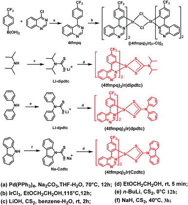
With this consideration, three sulfur atom containing dithiocarbamate derivatives constructed with different electron-donating groups (dipdtc = N,N-diisopropyl dithiocarbamate, dpdtc = N,N-diphenyl dithiocarbamate, and Czdtc = N-carbazolyl dithiocarbamate) as ancillary ligands were developed for Ir(III) complexes (4tfmpq)2Ir(dipdtc), (4tfmpq)2Ir(dpdtc) and (4tfmpq)2Ir(Czdtc) using the electron-deficient 4-(4-(trifluoromethyl)phenyl)quinazoline (4tfmpq) moiety as the cyclometalated ligand (Scheme 1) in this paper. Diphenylamine and carbazole are very classical hole transport units in OLED hole transport and host materials. The application of diphenylamine and carbazole in phosphorescent materials is more conducive to the balance of the distribution of holes and electrons, and is crucial for improving device efficiency and reducing roll-off. Moreover, the stable dithiolate compounds can reduce the work function of the emitter and the turn-on voltage in OLEDs.8 In addition, due to the nitrogen frame of the 4tfmpq ligand, these complexes would have bipolar properties, which are beneficial for their device performances.9
Results and discussion
Preparation and characterization of complexes
As shown in Scheme 1, three Ir(III) complexes were synthesized by the reaction of the [(C^N)2Ir(μ-Cl)]2 chloride-bridged dimer with dithiocarbamate derivatives. The four-membered heterocycle containing dithiocarbamate derivatives in (4tfmpq)2Ir(dipdtc), (4tfmpq)2Ir(dpdtc) and (4tfmpq)2Ir(Czdtc) were accessed by employing electron-rich units with bulkier backbone substituents to favor S,S-chelation of the electron-deficient Ir(III) center.5,6,10 Thus, the isopropyl, phenyl and carbazolyl moieties tend to push the lone pairs of electrons on the nitrogen atoms toward the metal center, which could greatly favor the chelating bonding mode.5,6,11 All complexes can be synthesized at room temperature in 5 min with high yields above 70% and good thermal stability (with decomposition temperature above 370 °C, Table 1 and Fig. S1†) owing to the strong coordination capability of the sulfur atom with the iridium atom, which is also helpful to boost their sublimation yields (>90%). Because most Ir(III) complexes were prepared at high temperature for a long time, the sulfur atom containing ligands developed in this study can reduce the cost of materials and OLED industrialization significantly.| Complex | T d (°C) | Absorptionb (λ nm) | Emissionb (λmax nm) | τ 298 K (μs) | Φ P (%) | E T (eV) | HOMO/LUMOe (eV) |
|---|---|---|---|---|---|---|---|
| a Decomposition temperature. b Measured in degassed CH2Cl2. c Φ: emission quantum yields were calculated with the fac-Ir(ppy)3 standard in degassed CH2Cl2 solution (ΦP = 0.4). d E T (triplet energy): estimated from the highest-energy peaks of the 77 K phosphorescence spectra in CH2Cl2 (10−5 M). e HOMO (eV) = −(Eox − E1/2,Fc) − 4.8, LUMO (eV) = HOMO + Ebandgap. | |||||||
| (4tfmpq)2Ir(dipdtc) | 384 | 263/285/453/592 | 641 | 1.41 | 58.3 | 2.04 | −5.44/−3.19 |
| (4tfmpq)2Ir(dpdtc) | 376 | 261/324/443/543 | 628 | 1.55 | 84.3 | 2.07 | −5.50/−3.20 |
| (4tfmpq)2Ir(Czdtc) | 371 | 282/357/532/570 | 611 | 1.50 | 93.0 | 2.18 | −5.61/−3.22 |
To further explore the reason for the rapid synthesis of these Ir(III) complexes, density functional theory (DFT) calculations at the B3LYP/Lanl2DZ12,13 level with the solvent effect treated using a SMD model14 were conducted. The calculated Gibbs free energy changes, ΔG, indicate that all three reactions are exothermic and thermodynamically favorable processes (from −59.4 to −94.9 kJ mol−1, Fig. 1). Assuming the formation of the two Ir–S bonds is stepwise, the kinetics of the complex formation by flexibly scanning the Ir–S bond length for the reaction of (4tfmpq)2Ir(dipdtc) were examined. The obtained potential energy surfaces show that as the S and Ir approach each other, the energy of the system gradually decreases until the equilibrium S–Ir bond length is reached. Further reduction of the S–Ir distance leads to a sharp energy increase (Fig. S2†). Hence, the formation of the S–Ir coordination bond does not involve the transition state of the conventional sense, and it is not necessary to overcome the corresponding energy barrier. The calculated free energy changes ΔG (−42.4 kJ mol−1, Fig. S3†) further demonstrate that the formation of the first Ir–S bond is thermodynamically favorable. The formation of the second Ir–S bond is similar to the first one, both kinetically and thermodynamically (−60.6 kJ mol−1, Fig. S3†).
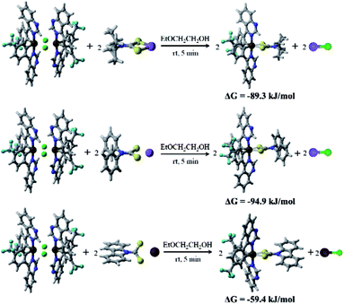 | ||
| Fig. 1 The calculated Gibbs free energy change ΔG of the three reactions of (4tfmpq)2Ir(dipdtc), (4tfmpq)2Ir(dpdtc) and (4tfmpq)2Ir(Czdtc) complexes. | ||
Molecular structures by the ORTEP drawing of the Ir(III) complexes (4tfmpq)2Ir(dipdtc) and (4tfmpq)2Ir(Czdtc) are shown in Fig. 2, and the crystallographic data and the selected bond lengths/angles are summarized in Tables S1 and S2 (ESI†), respectively. Both complexes have a distorted octahedral coordination geometry around the iridium center surrounded by three chelating ligands with cis-C–C and trans-N–N dispositions in which the N–Ir–N angles for these complexes are all almost 175°. The four-membered Ir–S–C–S backbones could lead to significantly more acute S–Ir–S bite angles (71.4° and 72.0°) than seen for the larger five-membered or six-membered heterocycles such as those based on pic and acac derivatives.5,15,16 In (4tfmpq)2Ir(Czdtc), the bond length of C3–S1 (1.710 Å) which is similar to that of C3–S2 (1.702 Å) also illustrates that −1 charge of dithiocarbamate is scattered over both sulfur atoms. The two coordinated S atoms of the ancillary ligand reside in the equatorial plane trans to the metalated C (4tfmpq) atoms. From the above analysis, this compact and tensile bonding mode is well understood.
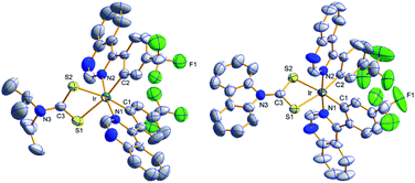 | ||
| Fig. 2 ORTEP diagram of (4tfmpq)2Ir(dipdtc) (CCDC no. 1832357) and (4tfmpq)2Ir(Czdtc) (CCDC no. 1832334) with the atom-numbering schemes. Hydrogen atoms are omitted for clarity. Ellipsoids are drawn at the 50% probability level. | ||
Electrochemical properties and theoretical calculations
The highest occupied molecular orbital (HOMO) and lowest unoccupied molecular orbital (LUMO) energy levels of the dopants are important for the structure design of OLEDs. To determine the HOMO/LUMO energy levels, the electrochemical behaviors of the three complexes were measured by cyclic voltammetry in CH2Cl2 solution at room temperature, relative to an internal ferrocenium/ferrocene reference (Fc+/Fc) (Fig. S4,† and Table 1). As revealed previously by electrochemistry and theoretical calculations of cyclometalated Ir(III) complexes, it is generally considered that the reduction process occurs mainly on the heterocyclic portion of the cyclometalated C^N ligands, whereas oxidation processes largely involve the Ir-aryl center and the ancillary ligand.17 Based on the above analysis, these complexes have almost equal LUMO energy levels (−3.19 to −3.22 eV) due to the same quinazoline-based frame, whereas their HOMO levels systematically change with the variation of the ancillary ligands from −5.44 eV of (4tfmpq)2Ir(dipdtc) containing diisopropylamine to −5.50 and −5.61 eV of (4tfmpq)2Ir(dpdtc) and (4tfmpq)2Ir(Czdtc) complexes, respectively, by introducing the diphenylamine and carbazole groups into the ancillary ligands. These results suggest that the diphenylamine and carbazole groups in the ancillary ligands would stabilize the HOMO level and positively shift the oxidation potentials.To obtain further electronic structure information, the HOMO/LUMO distributions of these Ir(III) molecules were also obtained with DFT calculations. As shown in Fig. S5,† the HOMO orbitals of the three Ir(III) complexes are mostly located on the 4tfmpq (43.55–47.90%) together with the d orbitals of the iridium atom (39.42–47.66%) with a small portion of the dithiocarbamate derivatives (8.66–12.67%). And a larger scale distribution of electron clouds on the iridium atom also indicates an efficient MLCT of the phosphorescent complexes, crucial to high PL quantum efficiency. With the decrease of the electron-donating ability of the substituents from diisopropylamine and diphenylamine to carbazole, the electron clouds distributed over the dithiocarbamate derivatives decrease gradually from 12.67% and 8.79% to 8.66%, which verifies the gradual change of the HOMO level of the corresponding complexes (Table S3†). The LUMOs are mostly distributed over the π* orbitals of the cyclometalated ligand (93.33–94.35%) and to a small extent on Ir d orbitals (3.45–4.13%) and ancillary ligands (2.20–2.34%). The calculated LUMOs remain almost unchanged, yet the HOMOs vary significantly, which correlate well with the electrochemical results (Table S3†).
Photophysical properties
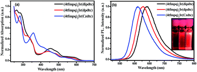
Fig. 3 shows the ultraviolet-visible absorption and photoluminescence spectra of (4tfmpq)2Ir(dipdtc), (4tfmpq)2Ir(dpdtc) and (4tfmpq)2Ir(Czdtc) complexes at room temperature in CH2Cl2, and their photophysical data are listed in Table 1. The intense absorption bands below 400 nm arise from the spin-allowed intraligand π → π* transitions, and the relatively weak bands in the visible region (400–630 nm) can be assigned to the mixed 1MLCT and 3MLCT (metal-to-ligand charge-transfer) states, or the LLCT (ligand-to-ligand charge-transfer) transition through strong spin–orbit coupling of the iridium atom.18 Compared with the complex (4tfmpq)2Ir(dipdtc) using the N,N-diisopropyl dithiocarbamate ancillary ligand (λpeak = 641 nm, Fig. 3(b)), complexes (4tfmpq)2Ir(dpdtc) containing N,N-diphenyl dithiocarbamate and (4tfmpq)2Ir(Czdtc) with N-carbazolyl dithiocarbamate exhibit 13 and 30 nm hypsochromic shifts, coinciding with the variation of calculated energy gaps.The PL quantum yields of the three Ir(III) complexes were measured as 58.3%, 84.3% and 93.0%, respectively, which may be attributed to the gradually increased rigidity of the corresponding Ir(III) complexes by gradually increasing the rigidity of the electron-donating substituents in the dithiocarbamate ancillary ligand from diisopropylamine and diphenylamine to carbazole. When the rigidity of the ligands is enhanced gradually, the non-radiative transitions caused by the vibration and rotation of a large number of C–H and C–C bonds are much reduced, which is also a way of energy consumption for the triplet states of the Ir(III) complexes. In addition, the lifetimes of the three complexes are in the microsecond range (1.41 μs for (4tfmpq)2Ir(dipdtc), 1.55 μs for (4tfmpq)2Ir(dpdtc) and 1.50 μs for (4tfmpq)2Ir(Czdtc), respectively) (Fig. S6†), which is indicative of the phosphorescence origin for the excited states in each case.
OLED performance
To illustrate their electroluminescence (EL) properties, typical OLEDs using these complexes as dopants were fabricated. Firstly, single-emissive-layer devices with ITO/HAT-CN (dipyrazino[2,3-f:2′,3′-h]quinoxaline-2,3,6,7,10,11-hexacarbonitrile, 6 nm)/HAT-CN (0.2 wt%):TAPC (di-[4-(N,N-ditolylamino) phenyl]cyclohexane, 50 nm)/(4tfmpq)2Ir(dipdtc) or (4tfmpq)2Ir(dpdtc) or (4tfmpq)2Ir(Czdtc) (3 wt%):2,6DCzPPy (2,6-bis(3-(carbazol-9-yl)phenyl)pyridine, 10 nm)/Tm3PyP26PyB (1,3,5-tris(6-(3-(pyridin-3-yl)phenyl)pyridin-2-yl) benzene, 60 nm)/LiF (1 nm)/Al (100 nm) are named as S1–S3, respectively. As shown in Scheme 2, the materials of HAT-CN and LiF served as hole- and electron-injecting interface modified materials, respectively. The bipolar material 2,6 DCzPPy was chosen as the host material. The TAPC material with a high HOMO level (−5.5 eV) acts as the hole-transport medium, and the layer of TAPC is doped with 0.2 wt% HAT-CN to further enhance the hole-transporting ability, while Tm3PyP26PyB with a low LUMO level (−2.7 eV) is used as the electron-accepting and electron-transport material. The HOMO and LUMO levels of Ir(III) complexes were all embedded between those of 2,6 DCzPPy (HOMO = 6.10 eV and LUMO = 2.60 eV). Thus, efficient energy transfer from the host to Ir(III) complexes occurred in the emitting layer (EML). Furthermore, holes and electrons can be injected to the HOMO and LUMO levels of the host material or trapped by the dopants directly owing to the difference of the HOMO/LUMO levels between the Ir(III) complexes and the host materials. And in the bipolar host 2,6 DCzPPy the excitons can be easily formed and distributed more balanced, which is helpful to reduce the turn-on voltage. All the devices were optimized and they display the best EL performances all at 3 wt% doping concentration, and the details of optimizing the doping concentration of Ir(III) emitters are included in the ESI.† The electroluminescence (EL) spectra, current density (J)–voltage (V)–luminance (L), current efficiency (ηc) and power efficiency (ηp) versus luminance, and EQE as a function of luminance characteristics of the devices are displayed in Fig. 4, and the parameters of these devices are summarized in Table 2.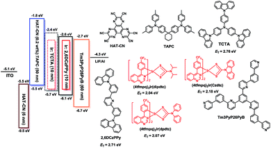 | ||
| Scheme 2 Energy level diagram of the HOMO and LUMO levels of materials investigated and their chemical molecular structures. | ||
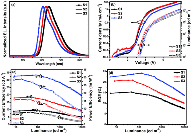 | ||
| Fig. 4 Characteristics of single-emitting-layer devices: (a) EL spectra, (b) J–V–L curves, (c) ηc–L–ηp curves and (d) EQE–L curves. | ||
| Device | V turn-on (V) | L max (cd m−2) | η c,max (cd A−1) | η ext,max (%) | η p,max (lm W−1) | η c (cd A−1) | η ext (%) | CIEc (x, y) |
|---|---|---|---|---|---|---|---|---|
| a Applied voltage recorded at a luminance of 1 cd m−2. b Recorded at 1000 cd m−2. c Measured at 1000 cd m−2. | ||||||||
| S1 | 3.4 | 26![[thin space (1/6-em)]](https://www.rsc.org/images/entities/char_2009.gif) 490 490 |
9.51 | 15.30 | 7.86 | 7.38 | 11.69 | (0.68, 0.31) |
| S2 | 3.2 | 39![[thin space (1/6-em)]](https://www.rsc.org/images/entities/char_2009.gif) 870 870 |
18.56 | 20.91 | 16.00 | 13.27 | 14.36 | (0.66, 0.33) |
| S3 | 3.4 | 56![[thin space (1/6-em)]](https://www.rsc.org/images/entities/char_2009.gif) 880 880 |
32.92 | 24.18 | 28.94 | 28.14 | 20.33 | (0.63, 0.36) |
| D1 | 3.6 | 33![[thin space (1/6-em)]](https://www.rsc.org/images/entities/char_2009.gif) 540 540 |
11.89 | 19.46 | 8.87 | 10.76 | 17.47 | (0.68, 0.31) |
| D2 | 3.4 | 46![[thin space (1/6-em)]](https://www.rsc.org/images/entities/char_2009.gif) 920 920 |
28.95 | 28.10 | 20.97 | 27.74 | 26.53 | (0.65, 0.33) |
| D3 | 3.6 | 60![[thin space (1/6-em)]](https://www.rsc.org/images/entities/char_2009.gif) 950 950 |
40.68 | 30.54 | 33.63 | 37.10 | 26.79 | (0.63, 0.36) |
Fig. 4(a) shows the normalized EL spectra of the three devices measured at the current of 1 mA with peaks at about 636, 621 and 605 nm for devices S1–S3, which are very close to the PL spectra of the three Ir(III) complexes, indicating that the EL emission of the devices originates from the triplet excited states of the phosphors in which all the Commission Internationale de 1′Eclairage (CIE) color coordinates fall in the red region. Due to the same cyclometalated ligand and similar molecular structures of the ancillary ligands, the device performances of these materials mainly depend on their PL efficiencies and bipolar properties. With the changes of the substituents from diisopropylamine and diphenylamine to carbazole, the resulting complexes from (4tfmpq)2Ir(dipdtc) and (4tfmpq)2Ir(dpdtc) to (4tfmpq)2Ir(Czdtc) exhibit more notable bipolar properties, better carrier balances and enhanced photoluminescence quantum efficiency, which would lead to the gradually enhanced OLED performances.
Respectively, the device S1 (ΦP of (4tfmpq)2Ir(dipdtc) is 58.3%) shows the lowest EL performances with a maximum luminance (Lmax) above 26![[thin space (1/6-em)]](https://www.rsc.org/images/entities/char_2009.gif) 000 cd m−2, a peak current efficiency (ηc,max) of 9.81 cd A−1, a peak power efficiency (ηp,max) of 7.86 lm W−1 and a maximum external quantum efficiency (EQEmax) of 15.30%. Relatively, the device S2 (ΦP of (4tfmpq)2Ir(dpdtc) is 84.3%) displays better performances with a Lmax, ηc,max and EQEmax of 39
000 cd m−2, a peak current efficiency (ηc,max) of 9.81 cd A−1, a peak power efficiency (ηp,max) of 7.86 lm W−1 and a maximum external quantum efficiency (EQEmax) of 15.30%. Relatively, the device S2 (ΦP of (4tfmpq)2Ir(dpdtc) is 84.3%) displays better performances with a Lmax, ηc,max and EQEmax of 39![[thin space (1/6-em)]](https://www.rsc.org/images/entities/char_2009.gif) 870 cd m−2, 18.56 cd A−1 and 20.91%, respectively. Due to the highest ΦP of (4tfmpq)2Ir(Czdtc) (93.0%), the device S3 exhibits the best characteristics with a Lmax, ηc,max and EQEmax of 56
870 cd m−2, 18.56 cd A−1 and 20.91%, respectively. Due to the highest ΦP of (4tfmpq)2Ir(Czdtc) (93.0%), the device S3 exhibits the best characteristics with a Lmax, ηc,max and EQEmax of 56![[thin space (1/6-em)]](https://www.rsc.org/images/entities/char_2009.gif) 880 cd m−2, 32.92 cd A−1 and 24.18%, respectively.
880 cd m−2, 32.92 cd A−1 and 24.18%, respectively.
In order to further improve the EL performances of these complexes, another hole transport material TCTA (4,4′,4′′-tris(carbazol-9-yl)triphenylamine) was introduced as the second host for these emitters and also as a “hole ladder” layer due to its suitable HOMO level (−5.70 eV) between TAPC and 26DCzPPy (Scheme 2). The OLEDs with double emissive layers with the configuration of ITO/HAT-CN (6 nm)/HAT-CN (0.2 wt%):TAPC (50 nm)/Ir(III) complexes (x wt%):TCTA (10 nm)/Ir(III) complexes (x wt%):2,6DCzPPy (10 nm)/Tm3PyP26PyB (60 nm)/LiF (1 nm)/Al (100 nm) using the dopants of (4tfmpq)2Ir(dipdtc), (4tfmpq)2Ir(dpdtc) and (4tfmpq)2Ir(Czdtc) are named as D1-D3, respectively (Scheme 2). The corresponding EL characteristics of the devices are shown in Fig. 5, and the detailed results are also summarized in Table 2. The stepwise changed HOMO energy levels of TAPC (−5.5 eV), TCTA (−5.7 eV) and 2,6DCzPPy (−6.1 eV) are beneficial for the hole injection and transport. Similarly, they are also beneficial for the injection and transport of electrons owing to the gradually changed LUMO energy levels of Tm3PyP26PyB (−2.7 eV), 2,6DCzPPy (−2.6 eV) and TCTA (−2.4 eV). Thus, holes and electrons will be distributed in more balanced emissive layers and the exciton recombination zone is expected to be broadened. Furthermore, the Tm3PyP26PyB HOMO energy level is 0.6 eV lower than that of 2,6DCzPPy and the TAPC LUMO energy level is 0.6 eV higher than that of TCTA, which will result in excitons (hole–electron pairs) being well conformed within emissive layers and the triplet exciton quenching being avoided effectively. From Fig. 5 and Table 2, it can be observed that all the devices with double emissive layers show better performances than S1–S3.
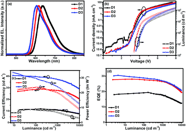 | ||
| Fig. 5 Characteristics of double emitting-layer devices: (a) EL spectra, (b) J–V–L, (c) ηc–L–ηp and (d) EQE–L curves. | ||
Respectively, D1 based on (4tfmpq)2Ir(dipdtc) at a doping concentration of 3 wt% displayed good performances with a Lmax above 33![[thin space (1/6-em)]](https://www.rsc.org/images/entities/char_2009.gif) 000 cd m−2, ηc,max over 11.89 cd A−1, ηp,max over 8.87 lm W−1 and EQEmax of 19.46%. The device D2 based on (4tfmpq)2Ir(dpdtc) at a doping concentration of 1 wt% displayed higher characteristics with a Lmax of 46
000 cd m−2, ηc,max over 11.89 cd A−1, ηp,max over 8.87 lm W−1 and EQEmax of 19.46%. The device D2 based on (4tfmpq)2Ir(dpdtc) at a doping concentration of 1 wt% displayed higher characteristics with a Lmax of 46![[thin space (1/6-em)]](https://www.rsc.org/images/entities/char_2009.gif) 920 cd m−2, an ηc,max of 28.95 cd A−1, an ηp,max of 20.97 lm W−1 and an EQEmax of 28.10% with CIE coordinates of (0.65, 0.33), which are quite close to the standard red demanded by the National Television System Committee (NTSC). Device D3 based on (4tfmpq)2Ir(Czdtc) with the N-carbazolyl dithiocarbamate ancillary ligand at 3 wt% doped concentration showed the best EL performances with a high brightness of 60
920 cd m−2, an ηc,max of 28.95 cd A−1, an ηp,max of 20.97 lm W−1 and an EQEmax of 28.10% with CIE coordinates of (0.65, 0.33), which are quite close to the standard red demanded by the National Television System Committee (NTSC). Device D3 based on (4tfmpq)2Ir(Czdtc) with the N-carbazolyl dithiocarbamate ancillary ligand at 3 wt% doped concentration showed the best EL performances with a high brightness of 60![[thin space (1/6-em)]](https://www.rsc.org/images/entities/char_2009.gif) 950 cd m−2 and the ηc,max, EQEmax and ηp,max are up to 40.68 cd A−1, 30.54% and 33.63 lm W−1, respectively. The CIE coordinates of (0.63, 0.36) also fall in the red region. The EQEs of 30.54% and the maximum brightness of 60
950 cd m−2 and the ηc,max, EQEmax and ηp,max are up to 40.68 cd A−1, 30.54% and 33.63 lm W−1, respectively. The CIE coordinates of (0.63, 0.36) also fall in the red region. The EQEs of 30.54% and the maximum brightness of 60![[thin space (1/6-em)]](https://www.rsc.org/images/entities/char_2009.gif) 950 cd m−2 are among the highest results ever reported for red Ir(III) complexes.7 Furthermore, the device efficiency roll-off is not serious. As for device D3, the ηc and EQE can still be obtained as 37.10 cd A−1 and 26.79%, respectively, when the luminance reaches 1000 cd m−2.
950 cd m−2 are among the highest results ever reported for red Ir(III) complexes.7 Furthermore, the device efficiency roll-off is not serious. As for device D3, the ηc and EQE can still be obtained as 37.10 cd A−1 and 26.79%, respectively, when the luminance reaches 1000 cd m−2.
Summarized from the investigated results, the superior device properties may result from the following facts. Firstly, dithiocarbamate derivatives with different electron-donating moieties and the nitrogen frame of 4-(4-(trifluoromethyl)phenyl)quinazoline were applied as the ancillary ligands and cyclometalated ligand for stable Ir(III) complexes with bipolar properties, which may contribute to a wider recombination area and a more balanced distribution for the excitons. Secondly, the coordination capability of the sulfur atom with the iridium atom is strong, and the stable dithiolate compounds can reduce the work function of the emitter and the threshold electric field.8 The different dithiocarbamate derivatives can lower the LUMO energy levels of the complexes, and the electron transport properties can benefit from lowering the LUMO levels of the dopants. Finally, double light-emitting layers were adopted, which showed improved and balanced charge-injection/transporting properties compared to single layer-emitting devices.19
Conclusions
In conclusion, three cyclometalated Ir(III) complexes containing the unique four-membered Ir–S–C–S backbone ring were rapidly prepared at room temperature with good yields above 70% and high PLQYs up to 93.0% in CH2Cl2. The Gibbs free energy calculation results confirm that all reactions are exothermic and thermodynamically favorable processes. Through changing the ancillary ligands with different electron-donating groups, the rigidity and bipolar properties of these Ir(III) complexes can be effectively tuned, resulting in regularly changed emission wavelength and OLED performances. The double-emissive-layer devices using the complex with N-carbazolyl dithiocarbamate as the ancillary ligand displays exceedingly good performances with a maximum brightness over 60![[thin space (1/6-em)]](https://www.rsc.org/images/entities/char_2009.gif) 000 cd m−2 and an EQEmax of 30.54%. Even at the brightness of 1000 cd m−2, the EQE can still be obtained as 26.79%, respectively. This study provides a useful route to synthesize Ir(III) complexes with the four-membered ring Ir–S–C–S structure rapidly, which is key to the industrial production of phosphorescent materials for high-performance OLEDs.
000 cd m−2 and an EQEmax of 30.54%. Even at the brightness of 1000 cd m−2, the EQE can still be obtained as 26.79%, respectively. This study provides a useful route to synthesize Ir(III) complexes with the four-membered ring Ir–S–C–S structure rapidly, which is key to the industrial production of phosphorescent materials for high-performance OLEDs.
Experimental section
Synthesis of the salts of dithiocarbamate derivatives
Synthesis of iridium(III) complexes
IrCl3 (0.64 g, 2.14 mmol) and 2.4 equivalents of cyclometalated ligand (5.14 mmol) were added in a 2-ethoxyethanol and water mixture. Then, the solution was heated for 16 h at 110 °C. After the addition of water, the precipitated red powder of [(C^N)2Ir(μ-Cl)]2 chloride-bridged dimer was filtered and reacted with dithiocarbamate derivatives without further purification for 5 minutes at room temperature in EtOCH2CH2OH. Then the solution was concentrated and the resulting residue was purified by silica gel column chromatography (CH2Cl2/petroleum ether 1![[thin space (1/6-em)]](https://www.rsc.org/images/entities/char_2009.gif) :
:![[thin space (1/6-em)]](https://www.rsc.org/images/entities/char_2009.gif) 2 (v/v)) and vacuum sublimation gave red crystals.
2 (v/v)) and vacuum sublimation gave red crystals.
Conflicts of interest
There are no conflicts to declare.Acknowledgements
This work was supported by the National Natural Science Foundation of China (51773088 and 21771172) and Youth Innovation Promotion Association of Chinese Academy of Sciences (Y72014).Notes and references
- (a) J. P. Duan, P. P. Sun and C. H. Cheng, Adv. Mater., 2003, 15, 224 CrossRef CAS; (b) G. J. Zhou, C. L. Ho, W. Y. Wong, Q. Wang, D. G. Ma, L. X. Wang, Z. Y. Lin, T. B. Marder and A. Beeby, Adv. Funct. Mater., 2008, 18, 499 CrossRef CAS; (c) S. Lamansky, P. Djurovich, D. Murphy, F. Abdel-Razzaq, H. E. Lee, C. Adachi, P. E. Burrows, S. R. Forrest and M. E. Thompson, J. Am. Chem. Soc., 2001, 123, 4304 CrossRef CAS.
- (a) T.-H. Han, Y. Lee, M.-R. Choi, S.-H. Woo, S.-H. Bae, B. H. Hong, J.-H. Ahn and T. W. Lee, Nat. Photonics, 2012, 6, 105 CrossRef CAS; (b) C. W. Lee and J. Y. Lee, Adv. Mater., 2013, 25, 5450 CrossRef CAS PubMed; (c) S.-Y. Kim, W.-I. Jeong, C. Mayr, Y.-S. Park, K.-H. Kim, J.-H. Lee, C.-K. Moon, W. Brütting and J.-J. Kim, Adv. Funct. Mater., 2013, 23, 3896 CrossRef CAS; (d) P. Tao, Y. Miao, Y. Zhang, K. Wang, H. Li, L. Li, X. Li, T. Yang, Q. Zhao, H. Wang, S. Liu, X. Zhou, B. Xu and W. Huang, Org. Electron., 2017, 45, 293 CrossRef CAS.
- (a) Q. Wang, I. W. H. Oswald, X. Yang, G. Zhou, H. Jia, Q. Qiao, Y. Chen, J. Hoshikawa-Halbert and B. E. Gnade, Adv. Mater., 2014, 26, 8107 CrossRef CAS; (b) K. Udagawa, H. Sasabe, C. Cai and J. Kido, Adv. Mater., 2014, 26, 5062 CrossRef CAS PubMed; (c) J.-H. Lee, S.-H. Cheng, S.-J. Yoo, H. Shin, J.-H. Chang, C.-I. Wu, K.-T. Wong and J.-J. Kim, Adv. Funct. Mater., 2015, 25, 361 CrossRef CAS; (d) P. Tao, Y. Zhang, J. Wang, L. Wei, H. Li, X. Li, Q. Zhao, X. Zhang, S. Liu, H. Wang and W. Huang, J. Mater. Chem. C, 2017, 5, 9306 RSC.
- (a) C.-Y. Lu, M. Jiao, W.-K. Lee, C.-Y. Chen, W.-L. Tsai, C.-Y. Lin and C.-C. Wu, Adv. Funct. Mater., 2016, 26, 3250 CrossRef CAS; (b) H. Shin, J.-H. Lee, C.-K. Moon, J.-S. Huh, B. Sim and J.-J. Kim, Adv. Mater., 2016, 28, 4920 CrossRef PubMed; (c) P. Tao, W. Li, J. Zhang, S. Guo, Q. Zhao, H. Wang, B. Wei, S. Liu, X. Zhou, Q. Yu, B. Xu and W. Huang, Adv. Funct. Mater., 2016, 26, 881 CrossRef CAS.
- (a) Q. Zhang, X. Wang, X. Wang, L. Wang and J. Zhang, Org. Electron., 2016, 33, 281 CrossRef; (b) P. Padungros and A. Wei, Synth. Commun., 2014, 44, 2336 CrossRef CAS PubMed; (c) S. C. Ngo, K. K. Banger, M. J. DelaRosa, P. J. Toscano and J. T. Welch, Polyhedron, 2003, 22, 1575 CrossRef CAS; (d) N. Su, Z. G. Wu and Y. X. Zheng, Dalton Trans., 2018, 47, 7587 RSC; (e) H. B. Han, Z. G. Wu, Z. P. Yan, Y. Zhao and Y. X. Zheng, Dalton Trans., 2018, 47, 16543 RSC.
- (a) D. Q. Gao, F. Scholz, H. G. Nothofer, W. E. Ford, U. Scherf, J. M. Wessels, A. Yasuda and F. V. Wrochem, J. Am. Chem. Soc., 2011, 133, 5921 CrossRef CAS PubMed; (b) L. Q. Chen, C. L. Yang, J. G. Qin, J. Gao, H. You and D. G. Ma, J. Organomet. Chem., 2006, 691, 3519 CrossRef CAS; (c) K. A. King, P. J. Spellane and R. J. Watts, J. Am. Chem. Soc., 1985, 107, 1431 CrossRef CAS; (d) A. Juris, V. Balzani, F. Barigelletti, S. Campagna, P. Belser and A. von Zelewsky, Coord. Chem. Rev., 1988, 84, 85 CrossRef CAS.
- (a) J. S. Wilson, N. Chawdhury, M. R. A. Al-Mandhary, M. Younus, M. S. Khan, P. R. Raithby, A. Köhler and R. H. Friend, J. Am. Chem. Soc., 2001, 123, 9412 CrossRef CAS; (b) G. Zhou, W.-Y. Wong, B. Yao, Z. Xie and L. Wang, Angew. Chem., Int. Ed., 2007, 119, 1167 CrossRef; (c) X. Cao, J. Miao, M. Zhu, C. Zhong, C. Yang, H. Wu, J. Qin and Y. Cao, Chem. Mater., 2015, 27, 96 CrossRef CAS; (d) M. Zhu, T. Ye, X. He, X. Cao, C. Zhong, D. Ma, J. Qin and C. Yang, J. Mater. Chem., 2011, 21, 9326 RSC; (e) J. Ding, J. Lü, Y. Cheng, Z. Xie, L. Wang, X. Jing and F. Wang, Adv. Funct. Mater., 2008, 18, 2754 CrossRef CAS; (f) D. H. Kim, N. S. Cho, H. Y. Oh, J. H. Yang, W. S. Jeon, J. S. Park, M. C. Suh and J. H. Kwon, Adv. Mater., 2011, 23, 2721 CrossRef CAS PubMed; (g) B. Jiang, X. W. Ning, S. L. Gong, N. Jiang, C. Zhong, Z. H. Lu and C. L. Yang, J. Mater. Chem., 2017, 5, 10220 RSC; (h) L. Chen, S. Wang, Z. Yan, J. Ding and L. Wang, J. Mater. Chem. C, 2017, 5, 5749 RSC; (i) C. Y. Kuei, W. L. Tsai, B. H. Tong, M. Jiao, W. K. Lee, Y. Chi, C. C. Wu, S. H. Liu, G. H. Lee and P. T. Chou, Adv. Mater., 2016, 28, 2795 CrossRef CAS PubMed; (j) Y. Q. Miao, P. Tao, K. X. Wang, H. X. Li, B. Zhao, L. Gao, H. Wang, B. S. Xu and Q. Zhao, ACS Appl. Mater. Interfaces, 2017, 9, 37873 CrossRef CAS PubMed.
- (a) T. Peng, H. Bi, Y. Liu, Y. Fan, H. Z. Gao, Y. Wang and Z. M. Hou, J. Mater. Chem., 2009, 19, 8072 RSC; (b) Q. B. Mei, C. Chen, R. Q. Tian, M. Yang, B. H. Tong, Q. F. Hua, Y. J. Shi, Q. L. Fan and S. H. Ye, RSC Adv., 2016, 6, 64003 RSC.
- (a) H. B. Han, R. Z. Cui, Y. M. Jing, G. Z. Lu, Y. X. Zheng, L. Zhou, J. L. Zuo and H. J. Zhang, J. Mater. Chem. C, 2017, 5, 8150 RSC; (b) H. B. Han, R. Z. Cui, G. Z. Lu, Z. G. Wu, Y. X. Zheng, L. Zhou and H. J. Zhang, Dalton Trans., 2017, 46, 14916 RSC.
- (a) C. Jones, P. C. Junk, J. A. Platts and A. Stasch, J. Am. Chem. Soc., 2006, 128, 2206 CrossRef CAS PubMed; (b) L. Zhang, M. Nishiura, M. Yuki, Y. Luo and Z. Hou, Angew. Chem., Int. Ed., 2008, 47, 2642 CrossRef CAS PubMed; (c) G. M. Li, P. Li, X. M. Zhuang, K. Q. Ye, Y. Liu and Y. Wang, ACS Appl. Mater. Interfaces, 2017, 9, 11749 CrossRef CAS PubMed.
- (a) J. A. R. Schmidt and J. Arnold, Chem. Commun., 1999, 2149 RSC; (b) D. Abeysekera, K. N. Robertson, T. S. Cameron and J. A. C. Clyburne, Organometallics, 2001, 20, 5532 CrossRef CAS; (c) S. Bambirra, D. van Leusen, A. Meetsma, B. Hessen and J. H. Teuben, Chem. Commun., 2003, 522 RSC.
- A. D. Becke, J. Chem. Phys., 1993, 98, 5648 CrossRef CAS.
- P. J. Hay and W. R. J. Wadt, Chem. Phys., 1985, 82, 270 CAS.
- A. V. Marenich, C. J. Cramer and D. G. Truhlar, J. Phys. Chem. B, 2009, 113, 6378 CrossRef CAS PubMed.
- P. J. Hay, J. Phys. Chem. A, 2002, 106, 1634 CrossRef CAS.
- (a) Q. B. Mei, L. X. Wang, Y. H. Gao, J. N. Weng, F. Yan, B. Tian and B. H. Tong, J. Mater. Chem., 2012, 22, 6878 RSC; (b) X. L. Yang, X. B. Xu, J. S. Dang, G. J. Zhou, C. L. Ho and W. Y. Wong, Inorg. Chem., 2016, 55, 1720 CrossRef CAS PubMed.
- J. Brooks, Y. Babayan, S. Lamansky, P. I. Djurovich, I. Tsyba, R. Bau and M. E. Thompson, Inorg. Chem., 2002, 41, 3055 CrossRef CAS PubMed.
- Y. T. Tao, C. L. Yang and J. G. Qin, Chem. Soc. Rev., 2011, 40, 2943 RSC.
- (a) Y. Jiang, L. Zhou, R. Cui, Y. Li, X. Zhao and H. Zhang, Dyes Pigm., 2016, 128, 26 CrossRef CAS; (b) X. Zhao, L. Zhou, Y. Jiang, R. Cui, Y. Li and H. Zhang, Dyes Pigm., 2016, 130, 148 CrossRef CAS.
Footnotes |
| † Electronic supplementary information (ESI) available: Details of materials, measurements, X-ray crystallography, electrochemical tests and theoretical calculations. Procedures of OLED fabrication and measurements. The crystallographic data, electronic cloud density distributions, TG curves, cyclic voltammograms and lifetime curves of Ir(III) complexes. The flexible scanning of the Ir–S bond length. The calculated free energy changes ΔG of formation of the two S–Ir coordination bonds. The isodensity surface plots and HOMO/LUMO orbital levels. Current efficiency versus luminance of devices with different doped concentrations. 1H NMR and 19F NMR spectra. CCDC 1832334 and 1832357. For ESI and crystallographic data in CIF or other electronic format see DOI: 10.1039/c8sc05605f |
| ‡ Lu and Su have the same contributions to this paper. |
| This journal is © The Royal Society of Chemistry 2019 |

