 Open Access Article
Bimolecular proximity of a ruthenium complex and methylene blue within an anionic porous coordination cage for enhancing photocatalytic activity†
Yu
Fang
 a,
Zhifeng
Xiao
 a,
Angelo
Kirchon
a,
Jialuo
Li
a,
Angelo
Kirchon
a,
Jialuo
Li
 a,
Fangying
Jin
a,
Tatsuo
Togo
b,
Liangliang
Zhang
a,
Fangying
Jin
a,
Tatsuo
Togo
b,
Liangliang
Zhang
 c,
Chengfeng
Zhu
d and
Hong-Cai
Zhou
 *ae
*ae
aDepartment of Chemistry, Texas A&M University, College Station, Texas 77842-3012, USA. E-mail: zhou@chem.tamu.edu
bDepartment of Chemistry, Faculty of Science, Kyushu University, 744 Motooka, Nishi-ku, Fukuoka, 819-0395, Japan
cInstitute of Flexible Electronics (IFE), Northwestern Polytechnical University, Xi'an, 710072, China
dAnhui Province Key Laboratory of Advanced Catalytic Materials and Reaction Engineering, School of Chemistry and Chemical Engineering, Hefei University of Technology, Hefei, 230009, P. R. China
eDepartment of Materials Science and Engineering, Texas A&M University, College Station, Texas 77842, USA
First published on 9th February 2019
Abstract
The charge repulsion between a catalyst and substrate will significantly reduce the contact occurring between them, resulting in low reactivity. Herein, we report an anionic porous coordination cage that is capable of encapsulating both a cationic catalyst and cationic substrate in its cavity at the same time. After encapsulating the [Ru(bpy)3]2+Cl2 (bpy = bipyridine) catalyst, the cage/catalyst composite serves as an active heterogeneous catalyst for the photo-degradation of methylene blue (MB). The highly negatively charged cavity of PCC-2 allows for the sequential encapsulation of the cationic methylene blue substrate and the Ru catalyst, which in turn significantly shortens the distance between them, yielding an increased possibility of MB degradation. Moreover, the encapsulated Ru catalyst dramatically outperformed its homogeneous counterpart in terms of overall degradation performance and recyclability.
Introduction
Over the course of scientific history, natural enzymes have traditionally exhibited the highest activity among all reported catalysts.1 The microenvironment of an enzyme pocket and active site contributes to the increased reaction rates for enzymes due to three main reasons. The first is that the encapsulation of substrates within the enzyme pocket increases the probability of reaction occurrence by reducing the free space for the substrates to exist in.2 Secondly, the enzyme pocket provides a more hydrophobic environment than the outer hydrophilic aqueous solution which leads to increased substrate adsorption.3 Lastly, the functional ancillary moieties/groups located inside or outside the binding pockets can stabilize reaction intermediates/transition states leading to increased reaction rates.2,3 In contrast, homogeneous metal catalysts sometimes display lower activity due to a comparatively low binding affinity for substrates, particularly when the two have the same charge. Therefore, synthetic hosts that mimic enzyme pockets are of great interest to the catalysis community in order to generate heterogeneous catalysts that rival the performance of natural enzymes.In the past few decades, it has been shown that the physical properties of an enzymatic environment, such as the pocket size, shape, and charge, can be finely mimicked within a synthetic host leading to increased and selective guest encapsulation.4 For example, Lehn, Cram, and Pedersen were the first to introduce crown ethers and cryptands as hosts that could capture guest molecules.5–9 Later, cyclodextrins were designed in order to provide an efficient “molecular flask” for manipulating reactivity. Even more recently, calixarenes have been an attractive material for manipulating host–guest chemistry, due to their ability to be easily modified on both their upper and lower rims.10–12 However, one problem with the examples provided is that they all display relatively small cavities which limits their application for the encapsulation of a wide variety of guest molecules.
On the other hand, as a member of the supramolecular family, porous coordination cages have shown promising results in guest adsorption chemistry, general catalysis, and even regio and stereoselective catalysis.13–18 Unlike the aforementioned classic host materials, these cages are self-assembled based upon the coordination bonds between the metal ions and organic ligands. In turn, the wide variety of metals and ligands that can be used has allowed coordination cages to display great structural diversity as well as be designed for specific functions. There are several classic examples of multi-functional cages that exhibit properties such as large diameter pores, hydrophobic cavities, solution stability, mono-dispersity in the solution state and even specific binding affinities towards guest molecules. However, the co-encapsulation of metal catalysts with organic substrates has rarely been reported. For example, Raymond et al. reported a cationic catalyst [Cp*(PMe3)Ir(Me)(CO)]+ that was encapsulated within the cavity of an anionic [M4L6]12− cage which was applied to C–H bond activation.19,20 Fujita et al. investigated pairwise encapsulation of trans-PdCl2(PEt3)2 and terminal alkynes by designing a cationic [M6L4]12+ cage.21 Overall, these coordination cages bind two kinds of guests in one confined cavity through charge and shape matching. Although current systems have been successful, they have some major limitations. First, cationic cages are not capable of encapsulating cationic species, which excludes most metal complexes. Secondly, the cavity diameter needs to be further extended in order to accommodate larger substrates and catalysts. Last but not least, the current coordination cages have only been shown to be effective in aqueous solution, while most catalytic reactions take place in organic solutions. Thus, a new design strategy for porous coordination cages is needed in order to fill the described gaps and further explore the host–guest chemistry in catalytic systems.
Previous work from our group demonstrated the capability of a highly negatively charged porous coordination cage named PCC-2.22,23 Herein, we applied PCC-2 for encapsulating a cationic [Ru(bpy)3]2+ (bpy = bipyridine) catalyst (Ru) and a cationic organic dye, methylene blue (MB). To the best of our knowledge, the co-encapsulation of a catalyst and a substrate of the same charge by a coordination cage has never been reported prior to this work. The cage–catalyst composite displays photocatalytic activity toward methylene blue degradation which is dramatically improved when compared to its homogeneous counterpart.
Results and discussion
Cage formation
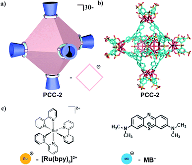
PCC-2 was synthesized according to previous literature by a solvothermal reaction using a vertex ligand (Na4H4V), panel ligand (H3L) and CoCl2.22,23 According to single crystal X-ray diffraction (SCXRD), PCC-2 is an octahedral cage which has a 2.5 nm large internal closed truncated-shaped cavity and 1.0 nm cavity apertures (Fig. 1a and b). Furthermore, according to ESI-MS analysis, PCC-2 is an anionic host with a formula of {[Co4(μ4-OH)V]6L8}30−, with 24 Na+ and 6 Et3NH+ ions as counter-cations. The anionic nature of PCC-2 makes it a reservoir for storing or exchanging cationic guests (Fig. 1c).Dye encapsulation
In order to explore the guest binding ability of PCC-2 for organic molecules, a cationic dye named methylene blue (MB) was selected as a model guest molecule (Fig. 2a). The host–guest interactions were investigated using a solid–liquid interface by soaking 10.0 mg of crystalline PCC-2 in an acetonitrile solution of MB (5 mg, 10 mL) for 40 min. The color of the supernatant was retained after 40 min, while the color of PCC-2 gradually turned dark purple (Fig. 2b). The decrease of MB concentration in the supernatant is demonstrated by a dramatic drop in the absorbance at 654 nm in the UV-vis absorption spectra. By comparing the MB concentration before and after encapsulation with the concentration of PCC-2, it was determined that 7 molecules of MB were encapsulated within the cavity of a single PCC-2 cage (wt% = 0.19 mg mg−1) (Fig. 2c). In addition, the UV-vis spectrum and elemental analysis were also applied in order to confirm the formation of the MB@PCC-2 composite as reported in the ESI (Fig. S1 and S2†). The MB encapsulation behavior matches with previously reported data.18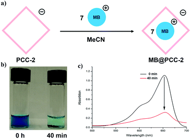 | ||
| Fig. 2 (a) Scheme for dye encapsulation by PCC-2; (b) image of MB solution after PCC-2 encapsulation for 0 min and 40 min; (c) UV-vis spectrum for MB solution recorded from 0 min to 40 min. | ||
Ruthenium catalyst encapsulation
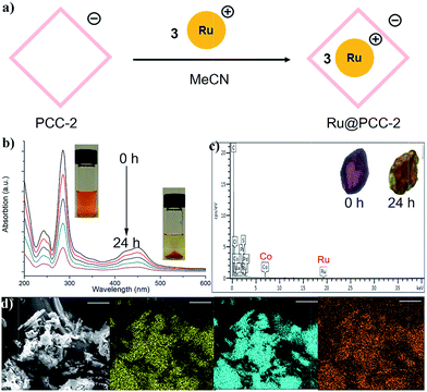
Since the anionic cavity of PCC-2 prefers to encapsulate cationic guest molecules, we replaced MB with [Ru(bpy)3]2+Cl2 (Ru) as another cationic guest (Fig. 3a). Following a similar procedure of guest encapsulation, it was calculated that 3 molecules of [Ru(bpy)3]2+ were encapsulated within the cavity of PCC-2 (Fig. 3b). The morphology of the PCC-2 crystals was maintained during the guest encapsulation, with a significant color change (Fig. 3c). Several attempts were made in order to solve the crystal structure of Ru@PCC-2 but all of them failed. The highly symmetric nature of PCC-2 crystals (trigonal) makes it difficult to identify the guest molecules within its cavities. After washing using organic solvents and drying in air, Ru@PCC-2 was fully characterized by UV-vis spectroscopy, SEM-EDX, and elemental analysis. The SEM-EDX clearly elucidated the weight percentage of Co and Ru elements as 7.79% and 1.48%, respectively. According to these data, the ratio of Co/Ru is 9/1, which matches the calculated ratio of 8/1 (There are 24 Co and 3 Ru atoms in the host–guest complex.) In addition, the UV-vis spectrum and elemental analysis were also applied in order to confirm the formation of the MB@PCC-2 composite as reported in the ESI (Fig. S3 and S4†). Through molecular modeling it was determined that only the internal cavity allows for the encapsulation of the Ru complex (Fig. S5†). Additionally, it was also calculated that there is still free space in the internal cavity of PCC-2 even after 3 Ru complexes were encapsulated which allows the remaining space in the cavity to be further used for guest encapsulation. Interestingly, when soaking Ru@PCC-2 in pure acetonitrile solvent, no guest leaking was detected even after 7 days. This can be attributed to the strong electrostatic attraction between the host (PCC-2) and the guest (Ru) which display opposite charges. After encapsulating three molecules of Ru catalyst (+2), the host–guest complex (Ru@PCC-2) maintains a −24 net charge and therefore is still capable of attracting cationic guests.Dye degradation
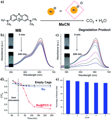
Next, the photocatalytic degradation of MB was conducted as a model reaction in order to investigate the efficiency of the catalyst–cage composite (Fig. 4a). In these reactions, 5.0 mg of Ru@PCC-2 (PCC-2: 3.55 × 10⁻⁴ mmol; Ru: 21.3 × 10⁻⁴ mmol) and 4.2 mg of PCC-2 (3.55 × 10⁻⁴ mmol) crystals in 50 mL of an acetonitrile solution of MB (50 mg) with a concentration of 3.13 mM (cal. 1000 ppm) were used. For comparison, the same degradation reaction using a homogeneous Ru catalyst at the same molar amount (1.6 mg, 21.3 × 10⁻⁴ mmol) was also performed as a control. The activity of the catalyst was monitored by measuring the maximum absorbance intensity of MB at 654 nm using a UV-vis spectrophotometer. Prior to visible light irradiation, the MB solution was placed in a dark environment in order to investigate the adsorption only. For the PCC-2 cage alone, the MB concentration was decreased by 9.9% within 40 min, which is due to dye adsorption. The MB concentration decreased visibly with a longer exposure time in the presence of photocatalysts Ru and Ru@PCC-2. In order to validate that the dye degradation was due to photolysis, the degradation of MB was performed in the absence of the Ru@PCC-2 or homogeneous Ru catalyst. This control reaction displayed negligible degradation after 24 hours, verifying that the degradation was performed by the Ru complexes (Fig. 4b). Furthermore, as shown in UV-vis spectra, the efficiency of photodegradation of MB is extremely low when using the homogeneous Ru catalyst. This is attributed to the charge repulsion of the substrate and the catalyst in solution. For Ru, only 19.8% degradation of MB was observed after 240 min under visible light irradiation. In contrast, the efficiency of photodegradation of MB was dramatically increased in the presence of Ru@PCC-2 (Fig. 4c). For Ru@PCC-2, about 94.9% degradation of MB was observed after 240 min under visible light irradiation.Next, several studies were performed in order to gain insight into the reaction kinetics and to further understand the photodegradation profile (Fig. 4d). It is worthy to note that, in the initial 20 min, the reaction rate of the heterogeneous Ru@PCC-2 is slower than that of the homogeneous Ru catalyst. This can be ascribed to diffusion limitations which are common for a heterogeneous catalyst. After 20 min, the reaction rate of Ru@PCC-2 is significantly higher than that of the homogeneous Ru catalyst. The experimental data were fitted using the first-order kinetic model as expressed by eqn (1).
| ln(C/C0) = kt | (1) |
C 0 and C are the initial and current concentration of MB, respectively, and k is the kinetic rate constant. The values of k were obtained from the slope between 20 min and 120 min, and the intercept of the linear plot. As seen in Fig. S6 and S7,† the Ru@PCC-2 composite exhibits a much higher rate constant (2.09 × 10⁻² min−1), which is about 5 times larger than that for the homogeneous Ru catalyst (0.06 × 10⁻² min−1). To the best of our knowledge, this is the first reported example of a metal–organic polyhedron/cage being used to encapsulate a Ru catalyst which results in an increase in its activity when compared to its homogeneous counterpart. The host–guest complex serves as a heterogeneous high-performance photocatalyst. Even compared to previously reported MOFs, Ru@PCC-2 has its unique advantages;25,26 first of all, the reaction does not involve any strong oxidizing agent, such H2O2, and the light source is just visible light, rather than UV light.24,27 A MOF photocatalyst ZnO@ZIF-8 achieved similar performance, but required high energy UV light (300 W high-pressure Hg lamp), instead of visible light (20 W) in our experimental setup.28 Secondly, the dosage of the photocatalyst (Ru@PCC-2, 5.0 mg) is less than that of Fe3O4@MIL-100 (10.0 mg) for a similar effect of degradation.24 Besides, the reaction rate of Ru@PCC-2 is among the highest values which can be obtained for Ru-doped MOF catalysts.29
In addition to the advances of its photocatalytic activity, the stability of the host–guest interactions was also evaluated by performing multiple cycles of MB photodegradation under visible light. Prior to each cycle, the photocatalyst was thoroughly washed using MeCN and dried in air after the reaction. Then, the catalyst was used for the next run of the experiment without any further treatment. After five cycles, Ru@PCC-2 still retained 92% MB removal efficiency with no obvious activity loss in MB photodegradation, indicating excellent long-term stability of Ru@PCC-2 (Fig. 4e). The catalyst before and after the reaction cycles was analyzed by UV-vis and ESI-MS. As shown in Fig. S8–S10,† it is confirmed that Ru@PCC-2 possesses good structural stability with no decomposition during MB photodegradation.
Mechanism investigation
The by-products generated during the degradation process were separated and analyzed by 1H NMR and ESI-MS. Compared with commercial standards, there are three major fragments, A, B, and C (Fig. 5a). Therefore, a reaction pathway can be proposed as shown in Fig. 5b, which is similar to the previously reported pathway of MB degradation using a TiO2 catalyst.30 According to the degradation products, MB was degraded via an oxidative pathway, which is typical for a Ru catalyst under visible light.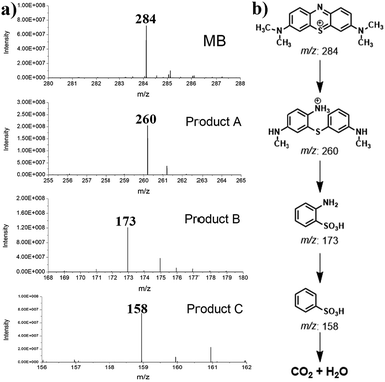 | ||
| Fig. 5 (a) ESI-MS spectrum of the isolated photodegradation product; (b) photodegradation pathway of MB according to the detected byproduct. | ||
Unlike most MOF photocatalysts, in which the frameworks contribute to the ligand-to-metal charge transfer (LMCT),24,27 PCC-2 plays the vital role of attracting both catalyst and substrates into its cavity, as well as offering the microenvironment for the reaction to take place (Fig. 6a). The reaction was concluded to take place at the ruthenium center since the activity is completely quenched in the absence of the Ru catalyst. Since ruthenium complexes have strong light absorption and high quantum efficiency, it is proposed that the  molecule is generated by light irradiation. The excited state of the
  molecule transfers electrons fairly easily to O2 and H2O in order to generate oxidative species such as ˙O2− and ˙OH. The photogenerated oxidative species (˙O2− and ˙OH) display strong oxidation capacities and can directly oxidize adsorbed MB molecules eventually generating CO2 and H2O (Fig. 6b).31
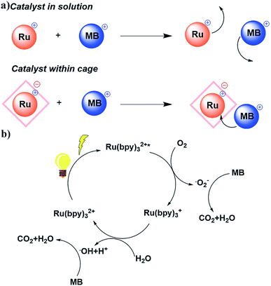 | ||
| Fig. 6 (a) Different reaction pathways for the Ru catalyst in solution and within the cage; (b) proposed reaction mechanism of MB photodegradation. | ||
Conclusions
In summary, we report an anionic porous coordination cage composite named Ru@PCC-2, which shows dramatically enhanced activity over its counterpart in solution. The −30 negatively charged cavity of PCC-2 encapsulates the cationic Ru(bpy)2+ and cationic MB+ molecules at the same time, in turn, putting the catalyst and substrate into close reaction proximity. Furthermore, the microenvironment of the cavity improved the activity of the encapsulated catalyst 35 times. PCC-2 is potentially suitable for encapsulating a wide spectrum of cationic metal complex catalysts, which can allow this chemistry to be used on a wide scale. Since coordination cages have been widely used in catalytic reactions,32–34 the catalyst–cage composite could be used for binding different guests/substrates, in order to explore novel reactions. Using a synthetic host to co-encapsulate metal catalysts and the substrate can also help tune catalyst reactivity as seen in enzymatic systems as well as explore novel selectivity for specific reactions.Conflicts of interest
There are no conflicts to declare.Acknowledgements
This work was supported by the Robert A. Welch Foundation (A-0030). We gratefully acknowledge the National Natural Science Foundation of China (NSFC Grant 21701187).Notes and references
- A. Stank, D. B. Kokh, J. C. Fuller and R. C. Wade, Acc. Chem. Res., 2016, 49, 809–815 CrossRef CAS PubMed.
- M. Gao and J. Skolnick, PLoS Comput. Biol., 2013, 9, e1003302 CrossRef PubMed.
- J. Dundas, L. Adamian and J. Liang, J. Mol. Biol., 2011, 406, 713–729 CrossRef CAS PubMed.
- D. J. Cram, Nature, 1992, 356, 29 CrossRef CAS.
- C. O. Mellet, J. M. G. Fernández and J. M. Benito, Chem. Soc. Rev., 2011, 40, 1586–1608 RSC.
- C. J. Pedersen, J. Am. Chem. Soc., 1967, 89, 2495–2496 CrossRef CAS.
- D. J. Cram, Science, 1983, 219, 1177–1183 CrossRef CAS PubMed.
- J. M. Lehn, Angew. Chem., Int. Ed., 2015, 54, 3276–3289 CrossRef CAS PubMed.
- G. Crini, Chem. Rev., 2014, 114, 10940–10975 CrossRef CAS PubMed.
- V. Böhmer, Angew. Chem., Int. Ed., 1995, 34, 713–745 CrossRef.
- A. F. Danil de Namor, R. M. Cleverley and M. L. Zapata-Ormachea, Chem. Rev., 1998, 98, 2495–2526 CrossRef PubMed.
- H. J. Kim, M. H. Lee, L. Mutihac, J. Vicens and J. S. Kim, Chem. Soc. Rev., 2012, 41, 1173–1190 RSC.
- A. C. Sudik, A. R. Millward, N. W. Ockwig, A. P. Côté, J. Kim and O. M. Yaghi, J. Am. Chem. Soc., 2005, 127, 7110–7118 CrossRef CAS PubMed.
- S. Sato, J. Iida, K. Suzuki, M. Kawano, T. Ozeki and M. Fujita, Science, 2006, 313, 1273–1276 CrossRef CAS PubMed.
- B. Olenyuk, J. A. Whiteford, A. Fechtenkötter and P. J. Stang, Nature, 1999, 398, 796 CrossRef CAS PubMed.
- P. Mal, B. Breiner, K. Rissanen and J. R. Nitschke, Science, 2009, 324, 1697–1699 CrossRef CAS PubMed.
- M. Liu, W. Liao, C. Hu, S. Du and H. Zhang, Angew. Chem., Int. Ed., 2012, 51, 1585–1588 CrossRef CAS PubMed.
- F.-R. Dai and Z. Wang, J. Am. Chem. Soc., 2012, 134, 8002–8005 CrossRef CAS PubMed.
- D. H. Leung, D. Fiedler, R. G. Bergman and K. N. Raymond, Angew. Chem., Int. Ed., 2004, 43, 963–966 CrossRef CAS PubMed.
- D. M. Kaphan, M. D. Levin, R. G. Bergman, K. N. Raymond and F. D. Toste, Science, 2015, 350, 1235–1238 CrossRef CAS PubMed.
- Y. Kohyama, T. Murase and M. Fujita, J. Am. Chem. Soc., 2014, 136, 2966–2969 CrossRef CAS PubMed.
- Y. Fang, J. Li, T. Togo, F. Jin, Z. Xiao, L. Liu, H. Drake, X. Lian and H.-C. Zhou, Chem, 2018, 4, 555–563 CAS.
- Y. Fang, Z. Xiao, J. Li, C. Lollar, L. Liu, X. Lian, S. Yuan, S. Banerjee, P. Zhang and H.-C. Zhou, Angew. Chem., Int. Ed., 2018, 57, 5283–5287 CrossRef CAS PubMed.
- C.-F. Zhang, L.-G. Qiu, F. Ke, Y.-J. Zhu, Y.-P. Yuan, G.-S. Xu and X. Jiang, J. Mater. Chem. A, 2013, 1, 14329 RSC.
- H.-P. Jing, C.-C. Wang, Y.-W. Zhang, P. Wang and R. Li, RSC Adv., 2014, 4, 54454–54462 RSC.
- M. Zhang, L. Wang, T. Zeng, Q. Shang, H. Zhou, Z. Pan and Q. Cheng, Dalton Trans., 2018, 47, 4251–4258 RSC.
- C. Yang, W. Dong, G. Cui, Y. Zhao, X. Shi, X. Xia, B. Tang and W. Wang, Sci. Rep., 2017, 7, 3973 CrossRef PubMed.
- X. Wang, J. Liu, S. Leong, X. Lin, J. Wei, B. Kong, Y. Xu, Z.-X. Low, J. Yao and H. Wang, ACS Appl. Mater. Interfaces, 2016, 8, 9080–9087 CrossRef CAS PubMed.
- R. N. Amador, M. Carboni and D. Meyer, RSC Adv., 2017, 7, 195–200 RSC.
- C. Yang, W. Dong, G. Cui, Y. Zhao, X. Shi, X. Xia, B. Tang and W. Wang, RSC Adv., 2017, 7, 23699–23708 RSC.
- R. Naumann, C. Kerzig and M. Goez, Chem. Sci., 2017, 8, 7510–7520 RSC.
- W. Xuan, M. Zhang, Y. Liu, Z. Chen and Y. Cui, J. Am. Chem. Soc., 2012, 134, 6904–6907 CrossRef CAS PubMed.
- C. Tan, J. Jiao, Z. Li, Y. Liu, X. Han and Y. Cui, Angew. Chem., Int. Ed., 2018, 57, 2085–2090 CrossRef CAS PubMed.
- W. Xuan, M. Zhang, Y. Liu, Z. Chen and Y. Cui, J. Am. Chem. Soc., 2018, 140, 2251–2259 CrossRef PubMed.
Footnote |
| † Electronic supplementary information (ESI) available. See DOI: 10.1039/c8sc05315d |
| This journal is © The Royal Society of Chemistry 2019 |

