
 Open Access Article
 This Open Access Article is licensed under a Creative Commons Attribution-Non Commercial 3.0 Unported Licence
A compatible anode/succinonitrile-based electrolyte interface in all-solid-state Na–CO2 batteries†
Yong
Lu
 ,
Yichao
Cai
,
Qiu
Zhang
,
Luojia
Liu
,
Zhiqiang
Niu
and
Jun
Chen
*
,
Yichao
Cai
,
Qiu
Zhang
,
Luojia
Liu
,
Zhiqiang
Niu
and
Jun
Chen
*
Key Laboratory of Advanced Energy Materials Chemistry (Ministry of Education), Renewable Energy Conversion and Storage Center, College of Chemistry, Nankai University, Tianjin 300071, China. E-mail: chenabc@nankai.edu.cn
First published on 12th March 2019
Abstract
All-solid-state sodium batteries have great potential for large-scale energy storage applications. However, constructing a compatible Na anode/solid-state electrolyte (SSE) interface is still challenging because most SSEs are unstable toward Na metal. A succinonitrile (SN) SSE shows high room-temperature ionic conductivity (10−3 S cm−1) but easily deteriorates if in contact with Na metal, leading to continuously increased interfacial resistance. Here we present an extremely simple approach to introduce a compact NaF-rich interphase on a Na surface via chemical reactions between fluoroethylene carbonate–Na+ and Na metal, resulting in a compatible Na anode/SN-based electrolyte interface. The in situ formed NaF-rich interphase can not only prevent side reactions between the SN-based electrolyte and Na anode but also regulate the uniform deposition of dendrite-free Na. As a result, the symmetric cells show a low overpotential of 150 mV after cycling for 4000 h. Furthermore, all-solid-state Na–CO2 batteries (4Na + 3CO2 ↔ 2Na2CO3 + C) with the compatible interface can run for 50 cycles with a small overpotential increase of 0.33 V. This work provides a promising method to build a stable interface that enables the use of an SSE which is unstable toward Na in Na metal batteries.
Introduction
Sodium batteries have been extensively studied in recent years because of the high abundance and low cost of Na resources.1–4 However, sodium batteries are mainly based on liquid electrolytes (such as ethers and carbonate esters), which would suffer from safety problems owing to the flammability of organic solvents and potential leakage of electrolytes.5–7 The problems would be more serious in sodium–air batteries because these batteries are open systems and the liquid electrolyte tends to evaporate easily, which restricts their further practical application.8–15 Recently, rechargeable Na–CO2 batteries have attracted much attention due to their high energy density (1125 W h kg−1) and the clean utilization of the greenhouse gas CO2. However, such batteries are often based on liquid or quasi-solid-state electrolytes and plagued by potential safety issues.16–26 Therefore, it is necessary to develop a solid-state electrolyte (SSE) for sodium batteries, especially sodium–air batteries, to improve their safety and avoid leakage of the electrolyte.To achieve high-performance solid-state sodium batteries, one of the key challenges is constructing a stable interface between the Na metal anode and the SSE, especially if the SSE is unstable toward Na.27–34 For example, succinonitrile (SN), a representative plastic-crystal electrolyte, has been applied in all-solid-state batteries because it can exhibit an ionic conductivity as high as 10−3 S cm−1 at room temperature.27,28 However, a SN electrolyte is unstable toward Na metal because the highly active Na metal can catalyze the polymerization of C![[triple bond, length as m-dash]](https://www.rsc.org/images/entities/char_e002.gif) N, leading to continuously increased interfacial resistance and unfavourable Na+ ion transfer (Fig. 1a).35 Similar to the SN electrolyte, there are many other SSEs which are unstable toward Na metal such as the representative inorganic sulfide-based electrolytes (Na3PS4 and Na3PSe4).30 Up to now, two strategies have been reported to achieve a stable interface between these SSEs and the anode. One is employing Na-alloys (such as Na15Sn4) instead of Na metal as anodes, which inevitably sacrifices the energy density of batteries.36,37 The other method is adding buffer layers (e.g., HfO2, Sc2O3, and ZrO2) between the Na anode and the SSE, which has only been supported by theoretical calculations.38 Moreover, the addition of pure inorganic buffer layers would lead to increased interfacial resistance and decreased energy density. Therefore, developing an effective way to avoid the side reactions and achieve a compatible interface between the unstable SSE and Na metal is of great significance.
N, leading to continuously increased interfacial resistance and unfavourable Na+ ion transfer (Fig. 1a).35 Similar to the SN electrolyte, there are many other SSEs which are unstable toward Na metal such as the representative inorganic sulfide-based electrolytes (Na3PS4 and Na3PSe4).30 Up to now, two strategies have been reported to achieve a stable interface between these SSEs and the anode. One is employing Na-alloys (such as Na15Sn4) instead of Na metal as anodes, which inevitably sacrifices the energy density of batteries.36,37 The other method is adding buffer layers (e.g., HfO2, Sc2O3, and ZrO2) between the Na anode and the SSE, which has only been supported by theoretical calculations.38 Moreover, the addition of pure inorganic buffer layers would lead to increased interfacial resistance and decreased energy density. Therefore, developing an effective way to avoid the side reactions and achieve a compatible interface between the unstable SSE and Na metal is of great significance.
 | ||
| Fig. 1 Schematic diagram of the compatibility between different Na metals and SN-based SSEs: (a) pristine Na metal, (b) 1 M NaClO4/FEC modified Na metal; the inset is the chemical reaction between FEC–Na+ and Na metal. (c) The energy levels/plots of the LUMO and highest occupied molecular orbital (HOMO) of FEC, Na+, and FEC–Na+. (d) Ab initio molecular dynamics models of the reactions between Na metal and FEC (top) or FEC–Na+ (bottom). | ||
Herein, we report an extremely simple approach to realize the compatible interface between the Na metal anode and the SN-based electrolyte via chemical reactions of fluoroethylene carbonate (FEC)–Na+ and Na (Fig. 1b). The selection of a proper reagent (1 M NaClO4/FEC) to treat Na metal is based on first-principles calculations (Fig. 1c and d). Owing to the in situ formed NaF-rich interphase on the surface of modified Na, the symmetric cells exhibit a small overpotential increase of 70 mV after cycling for 4000 h. Moreover, the all-solid-state Na–CO2 batteries with the modified Na anode and integrated SN-based SSE/MWCNT (multi-walled carbon nanotube) cathode could deliver high specific capacity (7624 mA h g−1 at 50 mA g−1), high cycling stability (overpotential increase of 0.33 V after 50 cycles), and high-rate performance. More importantly, the compatible anode/SN-based electrolyte interface could also be extended to other solid-state Na battery systems such as Na|Na3V2(PO4)3 batteries, which show a good capacity retention of 80% after 200 cycles and a high rate capability of 94 mA h g−1 at 2.0 C.
Results and discussion
Formation and characterization of the NaF-rich interphase
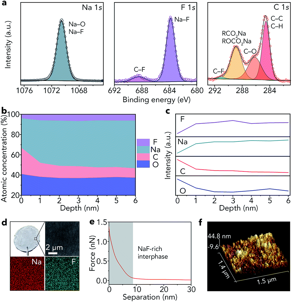
As shown in Fig. 1c, the lowest unoccupied molecular orbital (LUMO) energy level of FEC is 0.00 eV. After combining with a Na+ ion, the LUMO energy level of FEC decreases (−0.89 eV), implying that FEC–Na+ is more easily reduced by Na metal than pure FEC.39 These results are further confirmed by ab initio molecular dynamics simulation (Fig. 1d). For pure FEC, the five-membered heterocycle is first broken around 84 fs and then the cleavage of a C–F bond occurs at 117 fs. In contrast, the breakage of the heterocycle and C–F bond occurs more rapidly after FEC combines with a Na+ ion. In particular, the distance between Na and F (0.18 nm) is less than that in the NaF crystal (0.23 nm) after only 80 fs, implying the generation of NaF on the surface of Na metal. According to the theoretical calculations, we selected 1 M NaClO4/FEC rather than pure FEC to treat Na metal.We first dropped 1 M NaClO4/FEC on the surface of Na metal. After reaction for 5 s (the optimization of reaction time can be seen in Fig. S1†), we removed the residual NaClO4/FEC and the modified Na metal was obtained. The composition of the in situ formed interphase on the surface of Na metal was characterized by X-ray photoelectron spectrometry (XPS, Fig. 2a). The binding energy of Na 1s is observed at 1070.6 eV, corresponding to the Na–F and Na–O bonds.40 The F 1s peaks of Na–F and C–F are located at 683.8 and 688.5 eV, respectively. There are four different types of C, that is, C–C/C–H (284.5 eV), C–O (286.2 eV), RCOONa/ROCOONa (288.9 eV), and C–F (291.0 eV).41 The XPS results reveal that the interphase generated on the surface of Na metal mainly contains NaF and organic components (e.g., RONa, RCOONa, and ROCOONa). Furthermore, we use XPS to explore the spatial chemical distribution of the formed interphase. The results in Fig. 2b, c and S2† indicate that organic and inorganic components tend to be distributed in the top and bottom part, respectively. In addition, the formation of NaF was further confirmed by X-ray powder diffraction (XRD, Fig. S3†) and transmission electron microscopy (TEM, Fig. S4†). The infrared spectroscopy (IR) result in Fig. S5† further demonstrates the existence of organic constituents. Note that almost all the C, O, and F in the modified Na are only from the liquid reagent (1 M NaClO4/FEC) rather than from other contaminants, which was proved by energy dispersive X-ray spectroscopy of bare and modified Na (Fig. S6†).
 | ||
| Fig. 2 Characterization of the in situ formed NaF-rich interphase on the surface of Na metal. (a) High-resolution XPS spectra of Na 1s, F 1s, and C 1s, (b) atomic percentages and (c) relative elemental intensities at different depths, (d) optical photograph, SEM image, and elemental maps (Na and F), (e) retracted force–distance curve, and (f) AFM topography image with a 3D view. | ||
Compared with that of pristine Na metal (Fig. S7†), the surface of modified Na becomes gray (Fig. 2d). The scanning electron microscopy (SEM) image reveals that the surface of the modified Na is smooth. The smooth surface is also detected by topographic atomic force microscopy (AFM, Fig. 2f), where the surface roughness of modified Na metal is 6.15 nm (Fig. S8†). In addition, the elemental maps of Na and F in Fig. 2d indicate that NaF is distributed uniformly on the Na surface. The map of Young's modulus in Fig. S9† shows the good mechanical properties of the generated NaF-rich interphase. Moreover, the average deviation of Young's modulus is only 1.8 MPa (Fig. S10†). We further reveal the features of the NaF-rich interphase through the retracted force–distance curve (Fig. 2e). The results reveal that the thickness of the NaF-rich interphase is about 8 nm, which is close to the thickness of the solid electrolyte interphase in liquid electrolyte (e.g., 1 M NaPF6/monoglyme).40 The thin interphase leads to low interfacial resistance, which is very beneficial for Na+ ion transfer.
Synthesis and characterization of the SN-based electrolyte
We selected SN as the electrolyte for further study because the SN SSE shows high ionic conductivity (10−3 S cm−1).27,28 Due to the poor mechanical strength of the pure SN SSE, we added poly(vinylidene fluoride-co-hexafluoropropylene) (PVDF-HFP, Fig. 3a) to the electrolyte. We chose NaClO4 as the salt because of its low cost and good stability with CO2 and H2O. Through a facile solution-based casting approach, we can obtain a white solid-state membrane (Fig. 3b), whose surface is smooth (Fig. 3b). In addition, the SEM elemental maps of C, N, F, Na, Cl, and O in Fig. S11† indicate that SN, PVDF-HFP, and NaClO4 are distributed uniformly in the SSE. Then, we used TEM to further confirm the homogeneous molecular level distribution of the three different components in the SSE (Fig. 3c). The structure of the obtained SSE is confirmed by IR spectroscopy (Fig. 3d) and XRD (Fig. 3e). The high-polarity C–F bonds in PVDF-HFP are beneficial for the dissociation of NaClO4, resulting in decreased crystallinity of NaClO4 (Fig. 3e) and increased free Na+ ions in the SSE, which could contribute to enhancing the ionic conductivity.17,42 In addition, the crystallinity of PVDF-HFP decreases (Fig. 3e), reflecting the increased amount of the amorphous phase formed by the polymer chains, which also results in improved ionic conductivity.17,42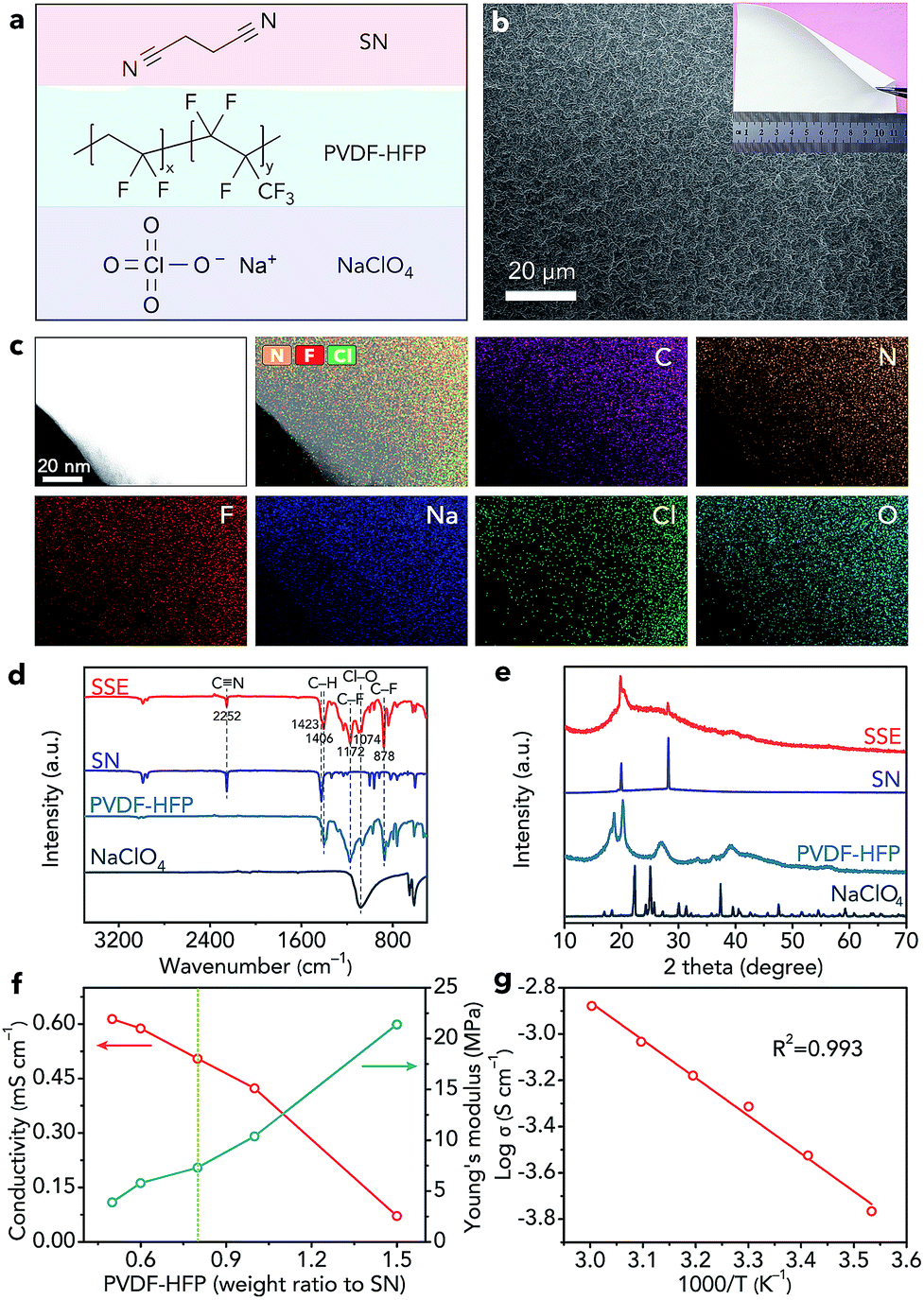 | ||
| Fig. 3 Characterization of the SN-based electrolyte. (a) Structural formula of SN, PVDF-HFP, and NaClO4. (b) SEM image and optical photograph (inset), and (c) TEM image and corresponding elemental maps (C, N, F, Na, Cl, and O) of the SN-based SSE. (d) IR spectra and (e) XRD patterns of SN, PVDF-HFP, NaClO4, and the SN-based SSE. (f) Ionic conductivity and Young's modulus of the SSE with different contents of PVDF-HFP. (g) Ionic conductivity of the optimal SSE at different temperatures (10, 20, 30, 40, 50, and 60 °C). | ||
To obtain the SSE with high ionic conductivity and good mechanical strength, we optimized the weight ratio of PVDF-HFP to SN. Before optimization, we fixed the molar ratio of SN to NaClO4 as 20![[thin space (1/6-em)]](https://www.rsc.org/images/entities/char_2009.gif) :1 because of its high ionic conductivity according to previous studies.27,28 When the weight ratio of PVDF-HFP increases from 0.5 to 1.5 (calculated based on the mass of SN), the Young's modulus of the SSE increases from 3.9 to 21.4 MPa (Fig. 3f and S12†), whereas the ionic conductivity decreases from 0.61 to 0.07 mS cm−1 (Fig. 3f). Considering the ionic conductivity and mechanical properties, we finally selected the SSE with a PVDF-HFP weight ratio of 0.8 as the optimal one, which exhibits a high ionic conductivity of 0.51 mS cm−1 and a good Young's modulus of 7.3 MPa. The ionic conductivity of the optimal SSE can reach 1.32 mS cm−1 at 50 °C (Fig. 3g). The slope of the fitted straight line in Fig. 3g is −1.63383. Thus, on the basis of the Arrhenius equation, we can find that the activation energy of the SSE is only 0.32 eV, which indicates favourable ion transfer. In addition, we studied the SSE using linear sweep voltammetry (Fig. S13†), which shows that the anodic decomposition potential is 4.86 V (vs. Na+/Na), implying high electrochemical stability of the SSE.43 The melting point of the SSE is about 105 °C (Fig. S14†), indicating the wide operating temperature range of the SSE. Moreover, the SSE exhibits good thermal stability (Fig. S15†).
:1 because of its high ionic conductivity according to previous studies.27,28 When the weight ratio of PVDF-HFP increases from 0.5 to 1.5 (calculated based on the mass of SN), the Young's modulus of the SSE increases from 3.9 to 21.4 MPa (Fig. 3f and S12†), whereas the ionic conductivity decreases from 0.61 to 0.07 mS cm−1 (Fig. 3f). Considering the ionic conductivity and mechanical properties, we finally selected the SSE with a PVDF-HFP weight ratio of 0.8 as the optimal one, which exhibits a high ionic conductivity of 0.51 mS cm−1 and a good Young's modulus of 7.3 MPa. The ionic conductivity of the optimal SSE can reach 1.32 mS cm−1 at 50 °C (Fig. 3g). The slope of the fitted straight line in Fig. 3g is −1.63383. Thus, on the basis of the Arrhenius equation, we can find that the activation energy of the SSE is only 0.32 eV, which indicates favourable ion transfer. In addition, we studied the SSE using linear sweep voltammetry (Fig. S13†), which shows that the anodic decomposition potential is 4.86 V (vs. Na+/Na), implying high electrochemical stability of the SSE.43 The melting point of the SSE is about 105 °C (Fig. S14†), indicating the wide operating temperature range of the SSE. Moreover, the SSE exhibits good thermal stability (Fig. S15†).
Compatible interface in symmetric cells
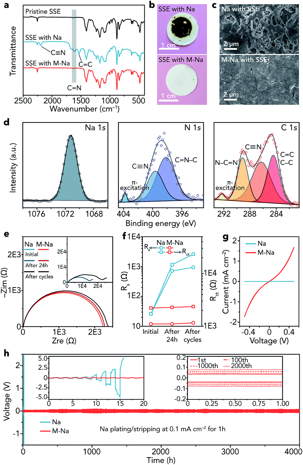
After obtaining the SN-based SSE and 1 M NaClO4/FEC modified Na metal (M-Na), we studied the interfacial compatibility between them in symmetric cells. As shown in Fig. 4a, the stretching vibrations of C![[double bond, length as m-dash]](https://www.rsc.org/images/entities/char_e001.gif) N (1614 cm−1), CC (1534 cm−1), and new CN (2194 cm−1) emerge in the IR spectrum of the SSE after cycling in pristine Na|Na symmetric cells (about 16 h), implying the polymerization of CN in SN. The degradation reaction of SN can be seen in Fig. S16.†35 In contrast, the IR spectrum of the SSE remains unchanged in M-Na|M-Na symmetric cells after cycling (4000 h), indicating that the NaF-rich interphase is very effective to cleanly separate Na and the SN-based SSE at the interface and avoid the side reactions between them. The optical photographs of the SSE after cycling further demonstrate the function of the NaF-rich interphase visually (Fig. 4b). A similar phenomenon can be found in Li metal batteries, where the interphase containing LiF and organic compounds could avoid the side reactions between the Li metal anode and the acetonitrile-based electrolyte.44
N (1614 cm−1), CC (1534 cm−1), and new CN (2194 cm−1) emerge in the IR spectrum of the SSE after cycling in pristine Na|Na symmetric cells (about 16 h), implying the polymerization of CN in SN. The degradation reaction of SN can be seen in Fig. S16.†35 In contrast, the IR spectrum of the SSE remains unchanged in M-Na|M-Na symmetric cells after cycling (4000 h), indicating that the NaF-rich interphase is very effective to cleanly separate Na and the SN-based SSE at the interface and avoid the side reactions between them. The optical photographs of the SSE after cycling further demonstrate the function of the NaF-rich interphase visually (Fig. 4b). A similar phenomenon can be found in Li metal batteries, where the interphase containing LiF and organic compounds could avoid the side reactions between the Li metal anode and the acetonitrile-based electrolyte.44
 | ||
| Fig. 4 Characterization and electrochemical performance of all-solid-state symmetric cells with pristine Na (Na|Na) and 1 M NaClO4/FEC modified Na (M-Na|M-Na). (a) IR spectra of the pristine SN-based SSE and SSE in different symmetric cells after cycling (Na: about 16 h, M-Na: 4000 h). (b) Optical photographs of the SSE and (c) SEM images of Na metal in different symmetric cells after cycling. (d) High-resolution XPS spectra of Na 1s, N 1s, and C 1s of pristine Na after cycling. (e) EIS results of different symmetric cells at the initial state, after resting for 24 h, and after cycling. (f) Rs and Rct of each EIS spectrum in (e). (g) CV curves in the voltage range of −0.5 to 0.5 V at 5 mV s−1 and (h) voltage profiles of different symmetric cells; the insets are the detailed voltage profiles. | ||
Then, we observed the change of Na metal in different symmetric cells after cycling. The surface of pristine Na becomes very rough and is filled with cracks (Fig. 4c), while the surface of modified Na remains smooth and dendrite-free even after cycling for 4000 h. The dendrite-free growth of Na metal can be mainly attributed to two aspects as follows. (1) The NaF rich interphase with specific spatial distribution features (top: organic, bottom: inorganic) is effective to uniformly arrange nucleation seeds of Na+ ions and induce homogeneous deposition of Na metal, resulting in inhibited growth of dendrites.45 Moreover, inorganic NaF (mainly distributed in the bottom part) shows relatively good mechanical properties, which is also beneficial for avoiding dendrites.46–49 (2) The SN-based SSE can act as an ion redistributor to homogenize Na+ ions, resulting in dendrite-free Na metal deposition.50 Furthermore, the XPS spectra of modified Na remain unchanged after cycling (Fig. S17†). In contrast, elemental N was detected on the surface of pristine Na after cycling (Fig. 4d). The binding energy of Na 1s (1071.2 eV) indicates the existence of Na metal.51 CN was detected (399.6 eV in N 1s and 286.3 eV in C 1s).52,53 Additionally, other peaks were observed, such as those for CN–C (398.2 eV, N 1s), N–CN (289.1 eV, C 1s), and CC/C–C (284.4 eV, C 1s).54–57 The XPS results reveal that the polymerization products of SN (Fig. S16†) exist on the surface of pristine Na after cycling.
The electrochemical impedance spectroscopy (EIS) results of the symmetric cells at different states (initial, after resting for 24 h, and after cycling) are shown in Fig. 4e, where Rs represents the resistance of the SN-based SSE and Rct reflects the charge-transfer resistance at electrolyte/electrode interfaces.58 After resting for 24 h and cycling, the Rs remains nearly unchanged in M-Na|M-Na cells but increases remarkably in Na|Na cells (Fig. 4f), demonstrating serious side reactions between pristine Na and the SN-based SSE. The evolution of Rct is similar to that of Rs, indicating a stable interface and fast charge-transfer kinetics between modified Na metal and the SN-based SSE. The fast kinetics can be further proved by the CV curves (Fig. 4g). The exchange current for Na plating/stripping in M-Na|M-Na cells is 1.73 mA cm−2, which is nearly three orders of magnitude higher than that in Na|Na cells.
Furthermore, the cycling stability of symmetric cells was evaluated through galvanostatic plating/stripping. The overpotential of Na|Na cells increases rapidly and reaches about 10 V at 0.1 mA cm−2 after only about 16 h (Fig. 4h), indicating the rather large resistance derived from the side reactions between Na and the SSE. In contrast, the Na plating/stripping in M-Na|M-Na cells remains remarkably stable (Fig. 4h). The overpotential increases by only 70 mV (from 80 to 150 mV) after 4000 h. To further demonstrate the interfacial compatibility, we investigated the electrochemical performance of M-Na|M-Na symmetric cells at higher current densities (0.2 and 0.5 mA cm−2) for higher capacity (1 mA h cm−2). As shown in Fig. S18,† the overpotentials of M-Na|M-Na cells can still remain stable during long cycling. The aforementioned results demonstrate the vital function of the NaF-rich interphase toward preventing the side reactions of Na metal/SN-based electrolyte and regulating the uniform deposition of Na.
Compatible interface in Na–CO2 batteries and beyond
We further used the modified Na metal as an anode to fabricate all-solid-state Na–CO2 batteries. The batteries are composed of a modified Na metal anode and an integrated SSE/MWCNT cathode (Fig. 5a). The integrated cathode includes the SN-based SSE, MWCNTs (Fig. S19†), and a carbon paper current collector (Fig. S20†). Prior to use, the MWCNTs were activated by acid treatment to introduce –COOH and –OH groups (Fig. S21†), which could promote the adsorption of CO2.17 The configuration of the batteries was confirmed from the cross-sectional SEM image and corresponding elemental maps of Na, F, and C (Fig. 5b). In addition, high-resolution SEM images show the intimate contact between not only the SSE and MWCNTs in the cathode (Fig. S22a†) but also the Na anode and integrated cathode (Fig. S22b†), which is very helpful for Na+ ion transfer within the batteries.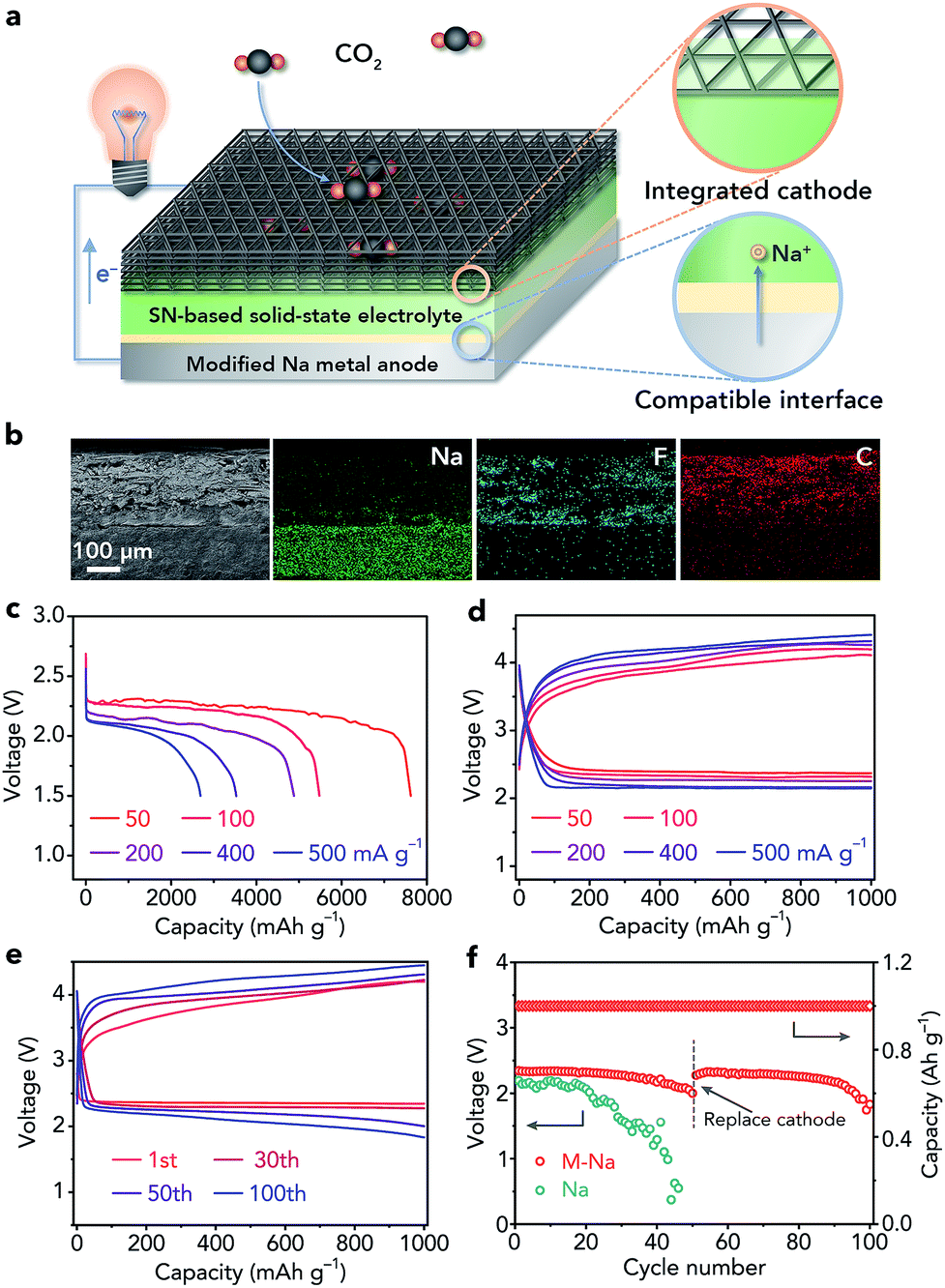 | ||
| Fig. 5 Configuration and electrochemical performance of all-solid-state Na–CO2 batteries. (a) Schematic illustration, and (b) cross-sectional SEM image and corresponding elemental maps (Na, F, and C) of the batteries. (c) Discharge curves with a cutoff voltage of 1.5 V, and (d) rate performance at different current rates (50, 100, 200, 400, and 500 mA g−1). (e) Discharge/charge profiles with a controlled specific capacity of 1000 mA h g−1 at 200 mA g−1 in selected cycles. (f) The terminal discharge voltages of batteries with the pristine and modified Na anode during cycling; the integrated cathode was replaced with a fresh one after 50 cycles. | ||
The reaction mechanism of all-solid-state Na–CO2 batteries was demonstrated by ex situ Raman spectroscopy (Fig. S23†), SEM (Fig. S24†), and TEM (Fig. S25†), and is well consistent with that in liquid or quasi-solid-state electrolyte-based Na–CO2 batteries (4Na + 3CO2 ↔ 2Na2CO3 + C).16–18 Then, we investigated the influence of the thickness of the SSE on the electrochemical performance (20–40, 50–70, and 80–100 μm, Fig. S26†). On the basis of the corresponding discharge/charge profiles (Fig. S27†), we selected the SSE with a moderate thickness (50–70 μm) for further studies.
The full discharge curves of Na–CO2 batteries at different rates (50, 100, 200, 400, and 500 mA g−1) with a cutoff voltage of 1.5 V are shown in Fig. 5c. The discharge capacity could reach 7624 mA h g−1 at 50 mA g−1 and still be maintained at 2689 mA h g−1 even at 500 mA g−1. Note that all the capacities and current densities are based on the mass of MWCNTs and the capacity derived from the carbon paper current collector is negligible (Fig. S28†). The overpotentials of the batteries in the second cycle are 1.53, 1.67, 1.85, 2.02, and 2.08 V at 50, 100, 200, 400, and 500 mA g−1, respectively, indicating high-rate performance (Fig. 5d). Then, we evaluate the cycling stability of the batteries with a controlled specific capacity of 1000 mA h g−1 at 200 mA g−1. The charge voltage does not increase obviously (Fig. 5e) and the terminal discharge voltage only decreases from 2.34 to 2.00 V after 50 cycles (Fig. 5f), implying good cycling performance of the all-solid-state Na–CO2 batteries.
To investigate whether the deteriorated cycling performance originated from the modified Na anode or the cathode, we replaced the integrated cathode with a fresh one after 50 cycles. The Na–CO2 batteries with the new cathode could show good cycling stability again (Fig. 5f), proving that the major problem that restricts the cyclability is the cathode rather than the anode. These results further demonstrate the high stability of the modified Na anode in Na–CO2 battery systems. In addition, we studied the cycling performance of the Na–CO2 batteries with a bare Na metal anode, which show continuously increased charge voltage (Fig. S29†) and decreased discharge voltage (Fig. 5f) owing to the serious side reactions between the Na anode and the SSE. Compared with other reported room-temperature metal–CO2 batteries, our fabricated all-solid-state Na–CO2 batteries with the modified Na anode exhibit relatively good comprehensive performance (Table S1†), which can be attributed to the compatible anode/electrolyte interface, high ionic conductivity of the SSE, activated MWCNTs, and integrated cathode.
Furthermore, we applied the modified Na metal anode in all-solid-state Na|Na3V2(PO4)3 batteries with the SN-based SSE (Fig. S30†). As shown in Fig. S31,† the batteries with the modified Na anode exhibit good cycling stability (capacity retention of 80% after 200 cycles) and superior rate performance (94 mA h g−1 at 2.0 C), which are far better than those of the batteries with the pristine Na anode. These results indicate the wide universality of the modified Na anode in batteries with the SN-based SSE. It is meaningful to extend this modified Na metal anode to match with other unstable SSEs such as Na3PS4 and Na3PSe4 in the future. Note that Na3V2(PO4)3 is actually a very stable cathode material in sodium-ion batteries.59 To reveal the reason why our fabricated Na|Na3V2(PO4)3 batteries did not exhibit excellent cycling performance, we studied the EIS plots of the Na3V2(PO4)3|Na3V2(PO4)3 symmetric batteries (with the SN-based SSE as the electrolyte) at different states. The results in Fig. S32† reveal that charge transfer resistance of the symmetric batteries gradually increases during cycling, indicating that there may be slight side reactions between Na3V2(PO4)3 and the SSE, which inevitably affect the cycling stability.
Conclusions
In summary, we have successfully developed an extremely simple method to modify Na metal and thus achieve a compatible interface of Na anode/electrolyte, especially for the SSE which is unstable toward Na metal. Owing to the robust and compact NaF-rich interphase on the surface of modified Na metal, the symmetric cells remain remarkably stable after 4000 h with a low overpotential of 150 mV. Moreover, the all-solid-state Na–CO2 batteries with the compatible interface show stable cycling performance (terminal discharge voltage of 2.00 V after 50 cycles) and high-rate capability. The compatible interface could also be extended to other solid-state systems such as Na|Na3V2(PO4)3 batteries. This work paves the way to construct a compatible interface of Na metal anode/unstable SSE and could stimulate the application of other unstable but high-performance SSEs in Na metal batteries.Conflicts of interest
There are no conflicts of interest to declare.Acknowledgements
This work was supported by the National Programs for Nano-Key Project (2017YFA0206700), the National Natural Science Foundation of China (21835004), and the 111 Project from the Ministry of Education of China (B12015). The calculations in this work were performed on TianHe-1(A), National Supercomputer Center in Tianjin.Notes and references
- S. K. Das, S. Xu and L. A. Archer, Electrochem. Commun., 2013, 27, 59–62 CrossRef CAS.
- S. Licht, A. Douglas, J. Ren, R. Carter, M. Lefler and C. L. Pint, ACS Cent. Sci., 2016, 2, 162–168 CrossRef CAS PubMed.
- Y. Lu, N. Zhang, S. Jiang, Y. Zhang, M. Zhou, Z. Tao, L. A. Archer and J. Chen, Nano Lett., 2017, 17, 3668–3674 CrossRef CAS PubMed.
- M. Bianchini, P. Xiao, Y. Wang and G. Ceder, Adv. Energy Mater., 2017, 7, 1700514 CrossRef.
- H. Che, S. Chen, Y. Xie, H. Wang, K. Amine, X.-Z. Liao and Z.-F. Ma, Energy Environ. Sci., 2017, 10, 1075–1101 RSC.
- Y. Lu, Y. Lu, Z. Niu and J. Chen, Adv. Energy Mater., 2018, 8, 1702469 CrossRef.
- Y. Kee, N. Dimov, S. Champet, D. H. Gregory and S. Okada, Ionics, 2016, 22, 2245–2248 CrossRef CAS.
- H. Yadegari and X. Sun, Acc. Chem. Res., 2018, 51, 1532–1540 CrossRef CAS PubMed.
- Q. Liu, Z. Chang, Z. Li and X. Zhang, Small Methods, 2018, 2, 1700231 CrossRef.
- S. Xu, Y. Yao, Y. Guo, X. Zeng, S. D. Lacey, H. Song, C. Chen, Y. Li, J. Dai, Y. Wang, Y. Chen, B. Liu, K. Fu, K. Amine, J. Lu and L. Hu, Adv. Mater., 2018, 30, 1704907 CrossRef PubMed.
- C. Xia, R. Black, R. Fernandes, B. Adams and L. F. Nazar, Nat. Chem., 2015, 7, 496–501 CrossRef CAS PubMed.
- K. Song, D. A. Agyeman, M. Park, J. Yang and Y. M. Kang, Adv. Mater., 2017, 29, 1606572 CrossRef PubMed.
- P. Hartmann, C. L. Bender, M. Vračar, A. K. Dürr, A. Garsuch, J. Janek and P. Adelhelm, Nat. Mater., 2013, 12, 228–232 CrossRef CAS PubMed.
- J. Kim, H.-D. Lim, H. Gwon and K. Kang, Phys. Chem. Chem. Phys., 2013, 15, 3623–3629 RSC.
- S. Zhang, M. J. Nava, G. K. Chow, N. Lopez, G. Wu, D. R. Britt, D. G. Nocera and C. C. Cummins, Chem. Sci., 2017, 8, 6117–6122 RSC.
- X. Hu, J. Sun, Z. Li, Q. Zhao, C. Chen and J. Chen, Angew. Chem., Int. Ed., 2016, 55, 6482–6486 CrossRef CAS PubMed.
- X. Hu, Z. Li, Y. Zhao, J. Sun, Q. Zhao, J. Wang, Z. Tao and J. Chen, Sci. Adv., 2017, 3, e1602396 CrossRef PubMed.
- C. Fang, J. Luo, C. Jin, H. Yuan, O. Sheng, H. Huang, Y. Gan, Y. Xia, C. Liang, J. Zhang, W. Zhang and X. Tao, ACS Appl. Mater. Interfaces, 2018, 10, 17240–17248 CrossRef CAS PubMed.
- J. Sun, Y. Lu, H. Yang, M. Han, L. Shao and J. Chen, Research, 2018, 2018, 6914626 Search PubMed.
- X. Wang, X. Zhang, Y. Lu, Z. Yan, Z. Tao, D. Jia and J. Chen, ChemElectroChem, 2018, 5, 3628–3632 CrossRef CAS.
- L. Qie, Y. Lin, J. W. Connell, J. Xu and L. Dai, Angew. Chem., Int. Ed., 2017, 56, 6970–6974 CrossRef CAS PubMed.
- Z. Zhang, X.-G. Wang, X. Zhang, Z. Xie, Y. N. Chen, L. Ma, Z. Peng and Z. Zhou, Adv. Sci., 2018, 5, 1700567 CrossRef PubMed.
- Y. Qiao, J. Yi, S. Wu, Y. Liu, S. Yang, P. He and H. Zhou, Joule, 2017, 1, 359–370 CrossRef CAS.
- W. Ma, X. Liu, C. Li, H. Yin, W. Xi, R. Liu, G. He, X. Zhao, J. Luo and Y. Ding, Adv. Mater., 2018, 30, 1801152 CrossRef PubMed.
- C. Li, Z. Guo, B. Yang, Y. Liu, Y. Wang and Y. Xia, Angew. Chem., Int. Ed., 2017, 56, 9126–9130 CrossRef CAS PubMed.
- T. N. Huan, P. Simon, G. Rousse, I. Génois, V. Artero and M. Fontecave, Chem. Sci., 2017, 8, 742–747 RSC.
- P.-J. Alarco, Y. Abu-Lebdeh, A. Abouimrane and M. Armand, Nat. Mater., 2004, 3, 476–481 CrossRef CAS PubMed.
- X. Zhu, R. Zhao, W. Deng, X. Ai, H. Yang and Y. Cao, Electrochim. Acta, 2015, 178, 55–59 CrossRef CAS.
- L. Sieuw, A. Jouhara, É. Quarez, C. Auger, J.-F. Gohy, P. Poizot and A. Vlad, Chem. Sci., 2019, 10, 418–426 RSC.
- Y. Lu, L. Li, Q. Zhang, Z. Niu and J. Chen, Joule, 2018, 2, 1747–1770 CrossRef CAS.
- A. Manthiram, X. Yu and S. Wang, Nat. Rev. Mater., 2017, 2, 16103 CrossRef CAS.
- A. Banerjee, K. H. Park, J. W. Heo, Y. J. Nam, C. K. Moon, S. M. Oh, S.-T. Hong and Y. S. Jung, Angew. Chem., Int. Ed., 2016, 55, 9634–9638 CrossRef CAS PubMed.
- S. S. Park, Y. Tulchinsky and M. Dincă, J. Am. Chem. Soc., 2017, 139, 13260–13263 CrossRef CAS PubMed.
- J. Song, B. Xiao, Y. Lin, K. Xu and X. Li, Adv. Energy Mater., 2018, 8, 1703082 CrossRef.
- D. Wöhrle and G. Knothe, J. Polym. Sci., Part A: Polym. Chem., 1988, 26, 2435–2447 CrossRef.
- X. Chi, Y. Liang, F. Hao, Y. Zhang, J. Whiteley, H. Dong, P. Hu, S. Lee and Y. Yao, Angew. Chem., Int. Ed., 2018, 57, 2630–2634 CrossRef CAS PubMed.
- A. Hayashi, K. Noi, A. Sakuda and M. Tatsumisago, Nat. Commun., 2012, 3, 856 CrossRef PubMed.
- H. Tang, Z. Deng, Z. Lin, Z. Wang, I.-H. Chu, C. Chen, Z. Zhu, C. Zheng and S. P. Ong, Chem. Mater., 2018, 30, 163–173 CrossRef CAS.
- X. Chen, X. Shen, B. Li, H.-J. Peng, X.-B. Cheng, B.-Q. Li, X.-Q. Zhang, J.-Q. Huang and Q. Zhang, Angew. Chem., Int. Ed., 2018, 57, 734–737 CrossRef CAS PubMed.
- Z. W. Seh, J. Sun, Y. Sun and Y. Cui, ACS Cent. Sci., 2015, 1, 449–455 CrossRef CAS PubMed.
- P. Verma, P. Maire and P. Novák, Electrochim. Acta, 2010, 55, 6332–6341 CrossRef CAS.
- X. Hu, G. Dawut, J. Wang, H. Li and J. Chen, Chem. Commun., 2018, 54, 5315–5318 RSC.
- P. Peljo and H. H. Girault, Energy Environ. Sci., 2018, 11, 2306–2309 RSC.
- N. D. Trinh, D. Lepage, D. Aymé-Perrot, A. Badia, M. Dollé and D. Rochefort, Angew. Chem., Int. Ed., 2018, 57, 5072–5075 CrossRef CAS PubMed.
- C. Yan, X.-B. Cheng, Y. Tian, X. Chen, X.-Q. Zhang, W.-J. Li, J.-Q. Huang and Q. Zhang, Adv. Mater., 2018, 30, 1707629 CrossRef PubMed.
- M. Han, C. Zhu, T. Ma, Z. Pan, Z. Tao and J. Chen, Chem. Commun., 2018, 54, 2381–2384 RSC.
- Y. Lee, J. Lee, J. Lee, K. Kim, A. Cha, S. Kang, T. Wi, S. J. Kang, H.-W. Lee and N.-S. Choi, ACS Appl. Mater. Interfaces, 2018, 10, 15270–15280 CrossRef CAS PubMed.
- Z. Zhu, Y. Tang, Z. Lv, J. Wei, Y. Zhang, R. Wang, W. Zhang, H. Xia, M. Ge and X. Chen, Angew. Chem., Int. Ed., 2018, 57, 3656–3660 CrossRef CAS PubMed.
- X. Zheng, C. Bommier, W. Luo, L. Jiang, Y. Hao and Y. Huang, Energy Storage Mater., 2019, 16, 6–23 CrossRef.
- C.-Z. Zhao, P.-Y. Chen, R. Zhang, X. Chen, B.-Q. Li, X.-Q. Zhang, X.-B. Cheng and Q. Zhang, Sci. Adv., 2018, 4, eaat3446 CrossRef PubMed.
- A. Barrie and F. J. Street, J. Electron Spectrosc. Relat. Phenom., 1975, 7, 1–31 CrossRef CAS.
- M. Barber, J. A. Connor, M. F. Guest, I. H. Hillier, M. Schwarz and M. Stacey, J. Chem. Soc., Faraday Trans. 2, 1973, 69, 551–558 RSC.
- B. A. Sexton and N. R. Avery, Surf. Sci., 1983, 129, 21–36 CrossRef CAS.
- J. Wang and W.-D. Zhang, Electrochim. Acta, 2012, 71, 10–16 CrossRef CAS.
- X. Xu, G. Liu, C. Randorn and J. T. S. Irvine, Int. J. Hydrogen Energy, 2011, 36, 13501–13507 CrossRef CAS.
- J. Cao, C. Chen, Q. Zhao, N. Zhang, Q. Lu, X. Wang, Z. Niu and J. Chen, Adv. Mater., 2016, 28, 9629–9636 CrossRef CAS PubMed.
- A. P. Dementjev, A. de Graaf, M. C. M. van de Sanden, K. I. Maslakov, A. V. Naumkin and A. A. Serov, Diamond Relat. Mater., 2000, 9, 1904–1907 CrossRef CAS.
- Q. Zhao, Z. Tu, S. Wei, K. Zhang, S. Choudhury, X. Liu and L. A. Archer, Angew. Chem., Int. Ed., 2018, 57, 992–996 CrossRef CAS PubMed.
- J. Zheng, S. Chen, W. Zhao, J. Song, M. H. Engelhard and J.-G. Zhang, ACS Energy Lett., 2018, 3, 315–321 CrossRef CAS.
Footnote |
| † Electronic supplementary information (ESI) available: Computational details, experimental section, and additional figures and tables as mentioned in the text. See DOI: 10.1039/c8sc05178j |
| This journal is © The Royal Society of Chemistry 2019 |