 Open Access Article
Integration of marker-free selection of single cells at a wireless electrode array with parallel fluidic isolation and electrical lysis†
Min
Li
and
Robbyn K.
Anand
 *
*
Department of Chemistry, Iowa State University, Ames, IA 50011, USA. E-mail: rkanand@iastate.edu
First published on 26th November 2018
Abstract
We present integration of selective single-cell capture at an array of wireless electrodes (bipolar electrodes, BPEs) with transfer into chambers, reagent exchange, fluidic isolation and rapid electrical lysis in a single platform, thus minimizing sample loss and manual intervention steps. The whole process is achieved simply by exchanging the solution in a single inlet reservoir and by adjusting the applied voltage at a pair of driving electrodes, thus making this approach particularly well-suited for a broad range of research and clinical applications. Further, the use of BPEs allows the array to be scalable to increase throughput. Specific innovations reported here include the incorporation of a leak channel to balance competing flow paths, the use of ‘split BPEs’ to create a distinct recapture and electrical lysis point within the reaction chamber, and the dual purposing of an ionic liquid as an immiscible phase to seal the chambers and as a conductive medium to permit electrical lysis at the split BPEs.
Introduction
Here we report a scalable dielectrophoretic cell array that integrates marker-free selection and sequestration of single cells with parallel lysis to prepare for analysis in one microfluidic platform. This approach is significant because (i) it addresses a need for development of versatile devices that integrate all steps needed for single-cell analysis (selection, isolation, assays), (ii) the whole manipulation process (capture, transfer, retention, and electrical lysis) was valve-free and achieved by only adjusting the applied voltage and exchanging the fluid in a single inlet, and (iii) the use of wireless bipolar electrodes (BPEs) allows facile arraying for increased throughput.Analysis of the composition and response of individual cells allows unique and differentiated subpopulations of cells to be delineated.1 Understanding cell-to-cell heterogeneity, such as in the expression of a particular gene2 or protein,3 concentration of an ion,4 or differences in regulatory and signaling patterns,5 helps define their distinct roles in disease states. In pathologies that are driven by a minority of cells, broad access to such information in research and clinical settings could revolutionize medicine. For instance, in cancer biology, the interrogation of individual circulating tumor cells (CTCs) provides key information that can inform therapeutic decisions.6 However, the enormous value of CTCs has not been completely realized because accurate cellular selection of CTCs is made challenging by their varied physical and biological characteristics and extreme rarity.7 For such rare cell applications, a key point is that integration of selection with parallel isolation and analysis of individual cells reduces device complexity and the likelihood of cell loss.
Many microfluidic lab-on-a-chip (LOC) technologies have been developed for manipulation and sampling of cells.8 However, they often suffer from the following issues: (i) most methods for single-cell isolation are not selective. Cells passively settle into divots9 or nanowells10 or are fluidically aligned prior to encapsulation into droplets.11 Selection must happen prior to the isolation step, and therefore, the overall process is necessarily modular. (ii) Selection methods based on immunoaffinity12 or size13 are either over-selective and miss certain cell populations, thus biasing results, or are under-selective and do not result in highly pure samples. (iii) Most existing capture and detection methods are not easily interfaced with assays. After capture, cells remain trapped on pillars,14 have been altered by molecular labels/tags,15 or become lost during transit to a secondary device.16 To facilitate assays in confined microstructures, embedded microvalves with a large number of control lines are often required.8b,17 The engineering complexity of these microvalves hinders their application in many research and clinical settings. Further, despite there being many lysis methods reported in microfluidics, integration of cell lysis with other functions to make a complete diagnostic system remains rare.18 Thus, development of fully integrated devices that offer simplicity in manufacturing and operation remains an important challenge.
Among cell manipulation techniques, dielectrophoresis (DEP) has distinct advantages in that it is highly selective, antibody independent and exhibits high output cell viability.19 Recent studies have demonstrated that this selectivity stems from biophysical properties with high biological relevance.20 Despite these advantages, most DEP sorting designs are not readily paired with single-cell assays. For instance, in dielectrophoretic field-flow fractionation (DEP-FFF),21 high-throughput continuous sorting of rare cells is achieved, but cells are not captured individually. Additionally, DEP-based strategies that integrate selection with analysis are frequently sequential, limiting throughput, or require transport of the cells for off-chip analysis, which risks cell loss.22 The Fujii group pioneered DEP capture in microwells for high-throughput analysis of confined cell lysates.23 However, the geometric constraints placed on the microwells limited the reaction volumes to only 56 pL, which is insufficient for certain assays such as single-cell RT-qPCR.24 Further, sealing microwells relies on mechanical actuation that collapses the overlying fluidic structure onto the array. An alternative DEP design that removes these constraints would improve design flexibility and better prevent crosstalk.
We previously developed the use of DEP at a BPE array to address the need for selective and high-throughput single-cell capture.7 In this device, BPE tips aligned to cell-sized micropockets accomplished individual capture of CTCs from a background of white blood cells (WBCs). BPEs do not require wire leads, which thereby allowed bifurcation to 32 parallel microchannels, greatly increasing throughput. In this way, this design took advantage of the ability of a BPE – a conductor immersed in an ionically conductive phase – to polarize in response to an externally applied electric field via charging of the electrical double layer (EDL) at its opposite ends.25 This charging effect communicates the voltage applied at just two driving electrodes across the entire BPE array. BPEs are versatile and have been employed previously for screening electrocatalysts,26,27 imaging,27 sensing,27,28 materials synthesis,29 micromotors,30 desalination,31 preconcentration of ionic species,32 and for DEP.7,33
This preliminary design did not incorporate reaction volumes for on-chip assays (e.g., for mutations, transcripts, or enzymatic activity). Separately, we recently reported insulating DEP (iDEP) capture at cell-sized constrictions and fluidic transfer of these cells into co-planar flow-through reaction chambers followed by thermal lysis and loop-mediated amplification (LAMP).34 This design utilizes the self-digitization (SD) principle to address the need for an isolated reaction volumes – an oil phase filled the fluidic channel and sealed off the chambers. A key advantage of this design is that capture efficiency is decoupled from the geometry of the reaction chamber, and therefore, the reaction volume could be independently tuned. However, the flow-through reaction chamber and traditional electrodes employed are not readily amenable to a bifurcation scheme, thus limiting throughput. Further, the fluidic resistance of these chambers was sufficiently low that imbalances in pressure resulted in both disruption of cell capture and intrusion of oil into the chamber.
In this paper, we integrate the advantages of both the BPE and SD schemes to accomplish selection, isolation, and electrical lysis – the steps required prior to molecular analysis of the contents of individual cells – in a valve-free and robust platform with a single inlet. While the approach is conceptually similar to the electroactive microwell device introduced by Fujii and coworkers, there are three key distinctions. First, there is only one fluidic layer, which greatly simplifies fabrication. Second, cell capture is accomplished at the reaction chamber inlet (instead of at the bottom of a reaction well), which critically provides independent control over reaction volume and capture efficiency. Third, and most importantly, the cell assay structures are readily fluidically isolated by an immiscible phase (SD principle) to prevent assay crosstalk. Beyond a simple combination of the BPE and SD schemes, a separate innovation is the incorporation of a split BPE inside the reaction chamber that allows electric field-directed cell recapture and electrical lysis. Finally, the use of ionic liquid (IL) as an electrically conductive substitute for oil allowed electrical lysis. These functions are accomplished with minimal peripheral equipment – a power supply and a microscope – thus increasing the relevance of this platform to broad application in research and clinical laboratories.
Results and discussion
As shown in Scheme 1a, DEP is a field-induced force exerted on a particle due to the interaction of the particle's frequency-dependent dipole moment with the spatial gradient of the electric field. Scheme 1b and c illustrate the pDEP and nDEP responses that we observed for model CTCs and WBCs, respectively, in our previously reported device.7 We have now advanced this design to enable analysis of the captured cells. Scheme 2a is an image of the device, which notably has only a single inlet and outlet and two electrical leads. Scheme 2b–h illustrate the steps of operation: (b) when an AC electric field is applied, cells of interest are selectively separated from the flowing sample and individually isolated in the pockets; (c and d) by turning the AC field ‘off’ and then ‘on’ again, the captured single-cells are further directed forward and retained at the center of the reaction chambers between adjacent BPE tips. (e) At this juncture, the fluid can be exchanged if warranted by the assay; (f) the microchannel is then filled with a hydrophobic IL to fluidically isolate the chambers. (g) Optionally, the AC field strength can then be increased to lyse captured cells. (h) This approach is therefore amenable to live cell assays or interrogation of cell contents. | ||
| Scheme 1 (a) Principles of pDEP attraction and nDEP repulsion in an external electric field and (b and c) near a BPE tip. | ||
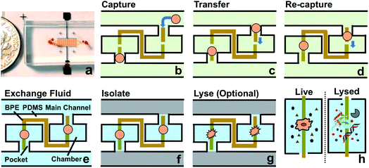 | ||
| Scheme 2 (a) Picture of the microfluidic chip. The channels are filled with red food dye to show detail. A coin is shown at the side for scale. (b–h) Schematic overview of the current approach. | ||
Leak channel enables valve-free transport and isolation of individual cells
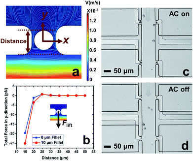
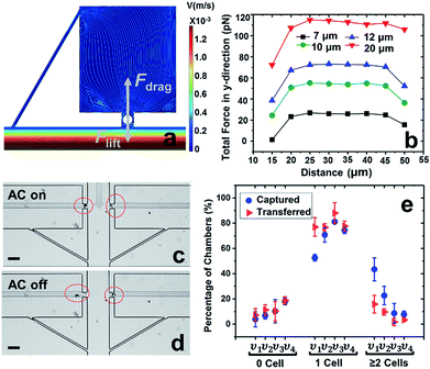
In our previous work,7 cell-scale micropockets extruding from either side of each microchannel ensured that individual cells were captured at each electrode tip. Here, reaction chambers are introduced adjacent to the pockets to store a sufficient amount of reagent solution (2.0 nL) for single-cell assay. Transfer of each cell from pocket to chamber must be accomplished to increase contact area between cells and reagents. However, the lift force created by fluid flow in the channel can easily pull the cell out of the pocket, once the capture voltage is turned off, and thereby impedes cell transfer into the chamber. Fig. 1 shows the results of cell transfer in the absence of a leak channel design. Fig. 1a is a surface plot showing the total fluid flow velocity in a segment of the main channel and a micropocket that contains a cell (represented by a white circle). In the y-direction, the cell experiences lift force (pressure force, towards the main channel) and drag force (viscous force, towards the chamber), while in the x-direction, only drag force is exerted on the cell. Positive total force along the y-direction is required for forward movement into reaction chambers. Fig. 1b is the computed result of the total force (FTotal) exerted on a cell when it is located in the pocket. The x-axis, as depicted in Fig. 1a, is the distance of the farthest edge of a cell (20.0 μm diameter) from the main channel opening. Importantly, this result was simulated for a design in which the reaction chamber has no additional fluidic connection (i.e., no leak channel). The BPE is not shown. Fig. 1c and d are sequential bright field images that show the result of turning off the AC voltage after cell capture. From this result, it can be concluded that in the absence of a leak channel, the drag force along the y-direction is negligible, while the lift force created by fluid flow can easily pull the cell out of the pocket. Additionally, a rounded pocket corner enhances lift force, and thereby impedes cell transfer. Based on the results, sharp pocket corners are desired, and it is further apparent that an additional force is required to push cells forward into the reaction chambers.We address this need by introducing a leak channel, which induces an additional drag force perpendicular to the main channel by forming a flow pathway into the micropocket and out of the leak channel (Fig. 2a). To investigate the influence of leak channel width and BPE location on cell transfer, the total force exerted on captured cells was computed (Fig. 2b). Based on these results, it can be concluded that FDrag is very sensitive to leak channel resistance, which increases exponentially with decreasing hydraulic radius. A 7 μm width permitted cell entry into the chamber without creating excessive drag force (stronger than DEP capture force), and was therefore chosen for subsequent experiments. Additionally, a distance (d, Fig. 2a) of 25–35 μm from the main channel to the farthest edge of the cell (20 μm diameter) prevents the cell from being washed away without compromising capture efficiency. It was found experimentally that this capture position was best achieved with a BPE tip positioned 5–15 μm inside the pocket.
Using this optimized design, MDA-MB-231 cells were successfully captured individually at each electrode tip when the AC capture voltage was on, and subsequently transferred into reaction chambers after turning off the AC voltage (Fig. 2c and d). To obtain optimal capture and transfer performance, the effect of flow rate was evaluated. As shown in Fig. 2e, increasing linear flow velocity from 80 μm s−1 to 120 μm s−1 reduced multi-cell capture, while going further to 150 μm s−1, the number of empty micropockets was significantly increased, leading to a decrease in the percentage of single-cell capture. At 120 μm s−1, excellent single cell capture (81.2%) and transfer (88.0%) were achieved. Therefore, 120 μm s−1 was chosen for subsequent experiments. These results are significant because they demonstrate the valve-free capture and sequestration of individual breast cancer cells in a scalable DEP device at an array of wireless electrodes.
Split BPE design enables selective recapture and retention of individual cells
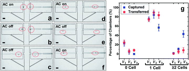
To prepare for on-chip molecular analysis of single cells, firm retention of isolated cells in the confined microstructures is crucial, especially if subsequent fluid exchange is required. To address such demand, we further developed a split BPE design, in which each single BPE employed previously was divided into two separate BPEs (Fig. 3a–f). Due to the electric field in the split, cells transferred into reaction chambers could be attracted and firmly retained there. This approach has the following advantages: (i) only cells that experience pDEP can be re-captured, which further enhances selective trapping of target cells, (ii) rapid fluid exchange can be conducted via both convection and diffusion (Fig. 4) since cells are held in place (Fig. 3d and f), and (iii) at electric field strengths required for DEP capture, cell viability is retained (important for live cell assays), while optionally, the voltage can be increased to lyse the cells.Considering that breaking of a single BPE into two individual BPEs gives rise to an additional potential drop in the ‘split’, a higher voltage is necessitated to achieve cell capture. Thus, the applied voltage was increased and the optimal voltage for the split BPE device was evaluated. As shown in Fig. 3g, at 18 Vpp, 23.3% of micropockets were empty, while this number dropped to 5.4% after increasing the capture voltage to 22 Vpp. A further increase to 26 Vpp resulted in 100% of pockets being filled. However, at this elevated voltage, the percentage of chambers containing multiple cells dramatically increased from 10.6% to 43.1%. Based on these results, 22 Vpp was selected as the optimal voltage to achieve single-cell capture (84.4%) and transfer (89.4%) in the split BPE design.
Fig. 3a–f depicts the cell manipulation process at 22 Vpp. Notably, after cell transfer is achieved with the AC field ‘off’, turning it ‘on’ again causes cells to be re-directed towards the split BPE and re-captured in the gap (Fig. 3e, f and S4†). These results demonstrate the ability of a split BPE to recapture an individual cell inside the chamber. Such recapture allows retention of the cell during fluid exchange and positions the cell for electrical lysis.
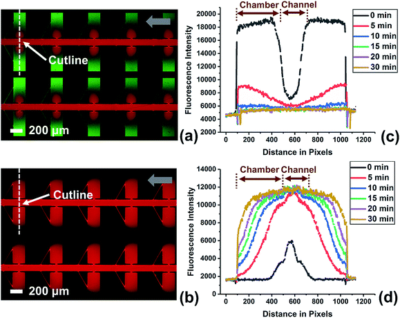
To investigate the efficiency of fluid exchange when allowed to occur primarily by diffusion, the device without a leak channel was employed. Fig. S3† shows the result obtained for the exchange of two solutions of fluorescent dye in DEP buffer. The device was first filled with green fluorescent dye at a flow rate of 0.1 μL min−1 by withdrawing from the outlet. Then, the solution in the inlet was exchanged for the red dye solution and fluorescence images were obtained at multiple time points (up to 1 h) after solution exchange. An important point is that the red dye is 70 kDa dextran tagged with Texas Red. Therefore, it has a diffusion coefficient that is more representative of a large biomolecule that may be incorporated into a reagent mixture for a bioassay. As a result, the exchange of the green dye (a small molecule) is much more rapid than for the red dye. As shown in Fig. S3c,† 78.4% of green dye was exchanged after 20 min, while red dye diffused into the chambers even after 60 min (Fig. S3d†). This slow rate of fluid exchange by diffusion contrasts the higher efficiency of fluid exchange by both convection and diffusion that is achieved when a leak channel is added (Fig. 4). Using the device with leak channels, the green dye solution could be completely replaced within 10 min, and the red dye reached the end (furthest edge) of reaction chambers after only 5 min. Therefore, the leak channel design allows DEP buffer to be exchanged with reagent solution rapidly, which decreases potential alteration of a target molecule and increases ease of use.
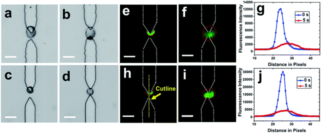
After cells were re-captured at the split BPEs, electric lysis was performed by stepping to a higher voltage for 5 s (Fig. 5). Upon electroporation, the cell membrane was disrupted and cells expanded, which is consistent with previously reported results.35 It was found that 100% of cells were lysed at 166 Vpp (Fig. S6†). Non-uniform lysis was observed from 112 Vpp to 166 Vpp (Fig. S5†) and is attributed to heterogeneous size distribution. Cells with small diameter have a higher threshold field strength for electroporation.35 To further confirm lysis, we demonstrated release of a membrane-permeant dye calcein from MDA-MB-231 cells. Upon electroporation, the fluorescence intensity immediately decreased, which indicates membrane disruption and calcein leakage (Fig. 5g and j).
Fluid isolation by ionic liquid inhibits cross-contamination and permits electrical lysis
Considering that cross-talk of adjacent chambers may affect the accuracy of the readout during cellular characterization, fluidic isolation of each individual reaction chamber is crucial. For live cell assays, digitization of each compartment could be conducted using a mixture of mineral oil and surfactant, as reported by the Chiu group.36 However, to assay cellular contents in the present device, the isolation fluid must be electrically conductive to enable electrical lysis. Moreover, the fluid must be hydrophobic and exhibit modest viscosity for liquid handling. Most importantly, the phase boundary needs to be stable throughout the subsequent assay.We addressed this need by choosing an IL as the immiscible phase considering its high hydrophobicity, low viscosity and electrical conductivity. Various flow patterns and flow rates were evaluated to achieve optimal fluidic isolation (Fig. S7–S9†). It was found that continuous flow at 0.1 μL min−1 allowed the fluid boundary to be maintained for at least 1 h without any propagation of IL into chambers. This result is significant because it demonstrates the potential for fluidic isolation using an IL for on-chip single-cell analysis.
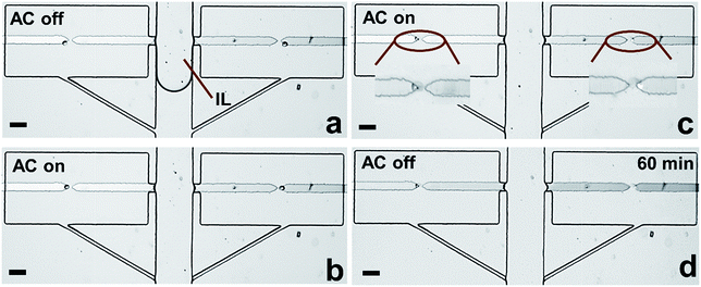
To further verify the robustness of the current technique, the entire workflow was conducted in sequence (Fig. S10†). Notably, after fluidic isolation using IL, 100% of captured cells were electrically lysed, and the buffer/IL boundary was maintained 1 h afterward (Fig. 6c and d). These results are significant because they demonstrate the integration of all steps required prior to analysis in one microfluidic unit. Notably, in our previous report,7 we demonstrated the selective capture of CTCs from WBCs at each micropocket. Therefore, the strategy demonstrated here not only meets the challenge of integration but also selectivity relevant to CTCs. In subsequent studies, we aim to exploit the flexibility in microchamber geometry to accomplish a variety of molecular analyses of individual cells.
Conclusion
In conclusion, we have developed a DEP-based approach for marker-free selection, isolation, and assay of single cells that is scalable and allows the reaction volume to be tuned. The process is amenable to either live cell assay or the assessment of cellular contents and is sufficiently inexpensive and easy to operate to be practical for broad application. Scalability permits sampling and analysis of larger input volumes. The current device has 2 parallel channels in a footprint of 15.6 mm2 and 40 reaction chambers. However, we previously demonstrated bifurcation to 32 parallel channels, which with 640 chambers would approach 2.5 cm2 and about 18 μL h−1 throughput, which is effective for many applications. The technology reported here is broadly applicable to individual analysis of many cell types and has a distinct advantage where cell phenotypes are distinguishable by their electrophysiological properties. In the context of CTCs, these dielectric properties are a much more specific differentiator of phenotype than size alone while not being as overly selective as a single biomarker such as EpCAM. Toner and coworkers recently demonstrated the wide range of CTC size and EpCAM expression thereby underscoring the need for alternatives to size- and antibody-based capture.37 This study is a premier example of the cutting edge in CTC detection, and importantly, it clearly demonstrates where there is remaining need – namely, to interface cell selection with single-cell isolation and subsequent assays. We anticipate that the platform reported here would be appropriate as secondary to an inline pre-sort for nucleated cells (e.g., by lateral displacement) with or without WBC depletion37 or to pre-enrichment by acoustophoresis.19b Finally, the isolation of individual cells at an array of wireless electrodes (BPEs), which are also frequently employed for sensing,38 presents the possibility for future integration of this technology with electrochemical methods of cell analysis.39Conflicts of interest
There are no conflicts to declare.Acknowledgements
The authors thank Prof. Jared Anderson and He Nan for providing ionic liquid samples for testing.References
- (a) X. Chen, J. C. Love, N. E. Navin, L. Pachter, M. J. Stubbington, V. Svensson, J. V. Sweedler and S. A. Teichmann, Nat. Biotechnol., 2016, 34, 1111–1118 CrossRef CAS PubMed; (b) L. Zhang and A. Vertes, Angew. Chem., Int. Ed., 2018, 57, 4466–4477 CrossRef CAS PubMed.
- C. Gawad, W. Koh and S. R. Quake, Nat. Rev. Genet., 2016, 17, 175–188 CrossRef CAS PubMed.
- S. S. Agasti, M. Liong, V. M. Peterson, H. Lee and R. Weissleder, J. Am. Chem. Soc., 2012, 134, 18499–18502 CrossRef CAS PubMed.
- L. Li, Y. Fan, Q. Li, R. Sheng, H. Si, J. Fang, L. Tong and B. Tang, Anal. Chem., 2017, 89, 4559–4565 CrossRef CAS PubMed.
- Q. Shi, L. Qin, W. Wei, F. Geng, R. Fan, Y. S. Shin, D. Guo, L. Hood, P. S. Mischel and J. R. Heath, Proc. Natl. Acad. Sci. U. S. A., 2012, 109, 419–424 CrossRef CAS PubMed.
- S. A. Joosse, T. M. Gorges and K. Pantel, EMBO Mol. Med., 2015, 7, 1–11 CrossRef CAS PubMed.
- M. Li and R. K. Anand, J. Am. Chem. Soc., 2017, 139, 8950–8959 CrossRef CAS PubMed.
- (a) B. J. Green, T. Saberi Safaei, A. Mepham, M. Labib, R. M. Mohamadi and S. O. Kelley, Angew. Chem., Int. Ed., 2016, 55, 1252–1265 CrossRef CAS PubMed; (b) R. N. Zare and S. Kim, Annu. Rev. Biomed. Eng., 2010, 12, 187–201 CrossRef CAS PubMed.
- D. Di Carlo, L. Y. Wu and L. P. Lee, Lab Chip, 2006, 6, 1445–1449 RSC.
- S. M. Park, D. J. Wong, C. C. Ooi, D. M. Kurtz, O. Vermesh, A. Aalipour, S. Suh, K. L. Pian, J. J. Chabon, S. H. Lee, M. Jamali, C. Say, J. N. Carter, L. P. Lee, W. G. Kuschner, E. J. Schwartz, J. B. Shrager, J. W. Neal, H. A. Wakelee, M. Diehn, V. S. Nair, S. X. Wang and S. S. Gambhir, Proc. Natl. Acad. Sci. U. S. A., 2016, 113, E8379–E8386 CrossRef CAS PubMed.
- H. N. Joensson and H. Andersson Svahn, Angew. Chem., Int. Ed., 2012, 51, 12176–12192 CrossRef CAS PubMed.
- (a) S. T. Wang, K. Liu, J. A. Liu, Z. T. F. Yu, X. W. Xu, L. B. Zhao, T. Lee, E. K. Lee, J. Reiss, Y. K. Lee, L. W. K. Chung, J. T. Huang, M. Rettig, D. Seligson, K. N. Duraiswamy, C. K. F. Shen and H. R. Tseng, Angew. Chem., Int. Ed., 2011, 50, 3084–3088 CrossRef CAS PubMed; (b) S. Wang, H. Wang, J. Jiao, K. J. Chen, G. E. Owens, K. Kamei, J. Sun, D. J. Sherman, C. P. Behrenbruch, H. Wu and H. R. Tseng, Angew. Chem., Int. Ed., 2009, 48, 8970–8973 CrossRef CAS PubMed.
- (a) V. De Giorgi, P. Pinzani, F. Salvianti, J. Panelos, M. Paglierani, A. Janowska, M. Grazzini, J. Wechsler, C. Orlando, M. Santucci, T. Lotti, M. Pazzagli and D. Massi, J. Invest. Dermatol., 2010, 130, 2440–2447 CrossRef CAS PubMed; (b) X. Fan, C. Jia, J. Yang, G. Li, H. Mao, Q. Jin and J. Zhao, Biosens. Bioelectron., 2015, 71, 380–386 CrossRef CAS PubMed.
- M. G. Ahmed, M. F. Abate, Y. Song, Z. Zhu, F. Yan, Y. Xu, X. Wang, Q. Li and C. Yang, Angew. Chem., Int. Ed., 2017, 129, 10821–10825 CrossRef.
- S. Hou, L. Zhao, Q. Shen, J. Yu, C. Ng, X. Kong, D. Wu, M. Song, X. Shi, X. Xu, W. H. OuYang, R. He, X. Z. Zhao, T. Lee, F. C. Brunicardi, M. A. Garcia, A. Ribas, R. S. Lo and H. R. Tseng, Angew. Chem., Int. Ed., 2013, 52, 3379–3383 CrossRef CAS PubMed.
- J. Cemazar, T. A. Douglas, E. M. Schmelz and R. V. Davalos, Biomicrofluidics, 2016, 10, 014109 CrossRef PubMed.
- A. K. White, K. A. Heyries, C. Doolin, M. Vaninsberghe and C. L. Hansen, Anal. Chem., 2013, 85, 7182–7190 CrossRef CAS PubMed.
- L. Nan, Z. Jiang and X. Wei, Lab Chip, 2014, 14, 1060–1073 RSC.
- (a) Z. R. Gagnon, Electrophoresis, 2011, 32, 2466–2487 CrossRef CAS PubMed; (b) M. Li and R. K. Anand, Anal. Bioanal. Chem., 2018, 410, 2499–2515 CrossRef CAS PubMed.
- A. R. Yale, J. L. Nourse, K. R. Lee, S. N. Ahmed, J. Arulmoli, A. Y. L. Jiang, L. P. McDonnell, G. A. Botten, A. P. Lee, E. S. Monuki, M. Demetriou and L. A. Flanagan, Stem Cell Rep., 2018, 11, 869–882 CrossRef CAS PubMed.
- P. R. Gascoyne, J. Noshari, T. J. Anderson and F. F. Becker, Electrophoresis, 2009, 30, 1388–1398 CrossRef CAS PubMed.
- (a) K. W. Huang, Y. C. Wu, J. A. Lee and P. Y. Chiou, Lab Chip, 2013, 13, 3721–3727 RSC; (b) P. Zhang, L. Ren, X. Zhang, Y. Shan, Y. Wang, Y. Ji, H. Yin, W. E. Huang, J. Xu and B. Ma, Anal. Chem., 2015, 87, 2282–2289 CrossRef CAS PubMed.
- S. H. Kim and T. Fujii, Lab Chip, 2016, 16, 2440–2449 RSC.
- (a) A. Ståhlberg and M. Kubista, Expert Rev. Mol. Diagn., 2014, 14, 323–331 CrossRef PubMed; (b) Y. Gong, A. O. Ogunniyi and J. C. Love, Lab Chip, 2010, 10, 2334–2337 RSC; (c) A. K. White, M. VanInsberghe, O. I. Petriv, M. Hamidi, D. Sikorski, M. A. Marra, J. Piret, S. Aparicio and C. L. Hansen, Proc. Natl. Acad. Sci. U. S. A., 2011, 108, 13999–14004 CrossRef CAS PubMed.
- (a) F. Mavré, R. K. Anand, D. R. Laws, K.-F. Chow, B. Y. Chang, J. A. Crooks and R. M. Crooks, Anal. Chem., 2010, 82, 8766–8774 CrossRef PubMed; (b) S. E. Fosdick, K. N. Knust, K. Scida and R. M. Crooks, Angew. Chem., Int. Ed., 2013, 52, 10438–10456 CrossRef CAS PubMed; (c) G. Loget, D. Zigah, L. Bouffier, N. Sojic and A. Kuhn, Acc. Chem. Res., 2013, 46, 2513–2523 CrossRef CAS PubMed.
- (a) S. E. Fosdick, S. P. Berglund, C. B. Mullins and R. M. Crooks, ACS Catal., 2014, 4, 1332–1339 CrossRef CAS; (b) S. E. Fosdick, S. P. Berglund, C. B. Mullins and R. M. Crooks, Anal. Chem., 2013, 85, 2493–2499 CrossRef CAS PubMed; (c) X. Zhang, L. Zhang, Q. Zhai, W. Gu, J. Li and E. Wang, Anal. Chem., 2016, 88, 2543–2547 CrossRef CAS PubMed; (d) X. Lin, L. Zheng, G. Gao, Y. Chi and G. Chen, Anal. Chem., 2012, 84, 7700–7707 CrossRef CAS PubMed.
- J. P. Guerrette, S. J. Percival and B. Zhang, J. Am. Chem. Soc., 2013, 135, 855–861 CrossRef CAS PubMed.
- (a) K.-F. Chow, F. Mavré and R. M. Crooks, J. Am. Chem. Soc., 2008, 130, 7544 CrossRef CAS PubMed; (b) W. Xu, K. Fu and P. W. Bohn, ACS Sens., 2017, 2, 1020–1026 CrossRef CAS PubMed; (c) A. Arora, J. C. T. Eijkel, W. E. Morf and A. Manz, Anal. Chem., 2001, 73, 3282–3288 CrossRef CAS PubMed.
- (a) J. C. Bradley and Z. Ma, Angew. Chem., Int. Ed., 1999, 38, 1663–1666 CrossRef CAS; (b) C. Ulrich, O. Andersson, L. Nyholm and F. Björefors, Angew. Chem., Int. Ed., 2008, 47, 3034–3036 CrossRef CAS PubMed; (c) R. Ramaswamy and C. Shannon, Langmuir, 2010, 27, 878–881 CrossRef PubMed; (d) S. Inagi, Y. Ishiguro, M. Atobe and T. Fuchigami, Angew. Chem., Int. Ed., 2010, 49, 10136–10139 CrossRef CAS PubMed; (e) S. Ramakrishnan and C. Shannon, Langmuir, 2010, 26, 4602–4606 CrossRef CAS PubMed.
- (a) Z. Fattah, G. Loget, V. Lapeyre, P. Garrigue, C. Warakulwit, J. Limtrakul, L. Bouffier and A. Kuhn, Electrochim. Acta, 2011, 56, 10562–10566 CrossRef CAS; (b) G. Loget and A. Kuhn, J. Am. Chem. Soc., 2010, 132, 15918–15919 CrossRef CAS PubMed.
- (a) K. N. Knust, D. Hlushkou, R. K. Anand, U. Tallarek and R. M. Crooks, Angew. Chem., Int. Ed., 2013, 52, 8107–8110 CrossRef CAS PubMed; (b) E. Yoon, C. D. Davies, T. A. Hooper and R. M. Crooks, Lab Chip, 2017, 17, 2491–2499 RSC.
- (a) R. K. Anand, E. Sheridan, K. Knust and R. M. Crooks, Anal. Chem., 2011, 83, 2351–2358 CrossRef CAS PubMed; (b) D. R. Laws, D. Hlushkou, R. K. Perdue, U. Tallarek and R. M. Crooks, Anal. Chem., 2009, 81, 8923–8929 CrossRef CAS PubMed; (c) K. Scida, E. Sheridan and R. M. Crooks, Lab Chip, 2013, 13, 2292–2299 RSC.
- (a) R. K. Anand, E. S. Johnson and D. T. Chiu, J. Am. Chem. Soc., 2015, 137, 776–783 CrossRef CAS PubMed; (b) Y. Wu, Y. Ren, Y. Tao, L. Hou and H. Jiang, Anal. Chem., 2018, 90, 11461–11469 CrossRef CAS PubMed.
- Y. Qin, L. Wu, T. Schneider, G. S. Yen, J. Wang, S. Xu, M. Li, A. L. Paguirigan, J. L. Smith, J. P. Radich, R. K. Anand and D. T. Chiu, Angew. Chem., Int. Ed., 2018, 57, 11378–11383 CrossRef CAS PubMed.
- H. Y. Wang and C. Lu, Anal. Chem., 2006, 78, 5158–5164 CrossRef CAS PubMed.
- D. E. Cohen, T. Schneider, M. Wang and D. T. Chiu, Anal. Chem., 2010, 82, 5707–5717 CrossRef CAS PubMed.
- F. Fachin, P. Spuhler, J. M. Martel-Foley, J. F. Edd, T. A. Barber, J. Walsh, M. Karabacak, V. Pai, M. Yu, K. Smith, H. Hwang, J. Yang, S. Shah, R. Yarmush, L. V. Sequist, S. L. Stott, S. Maheswaran, D. A. Haber, R. Kapur and M. Toner, Sci. Rep., 2017, 7, 10936 CrossRef PubMed.
- S. E. Fosdick, K. N. Knust, K. Scida and R. M. Crooks, Angew. Chem., Int. Ed., 2013, 52, 10438 CrossRef CAS PubMed.
- T. E. Lin, S. Rapino, H. H. Girault and A. Lesch, Chem. Sci., 2018, 9, 4546 RSC.
Footnote |
| † Electronic supplementary information (ESI) available: Materials and methods, details of experimental procedures, and supplementary results of fluid exchange, lysis, and fluidic isolation steps. See DOI: 10.1039/c8sc04804e |
| This journal is © The Royal Society of Chemistry 2019 |

