
 Open Access Article
 This Open Access Article is licensed under a Creative Commons Attribution-Non Commercial 3.0 Unported Licence
Energy-storage covalent organic frameworks: improving performance via engineering polysulfide chains on walls†
Fei
Xu
 a,
Shuhao
Yang
a,
Xiong
Chen
*b,
Qianhui
Liu
a,
Hejun
Li
a,
Hongqiang
Wang
a,
Bingqing
Wei
a and
Donglin
Jiang
*cd
a,
Shuhao
Yang
a,
Xiong
Chen
*b,
Qianhui
Liu
a,
Hejun
Li
a,
Hongqiang
Wang
a,
Bingqing
Wei
a and
Donglin
Jiang
*cd
aState Key Laboratory of Solidification Processing, Center for Nano Energy Materials, School of Materials Science and Engineering, Northwestern Polytechnical University, Shaanxi Joint Laboratory of Graphene (NPU), Xi'an, 710072, P. R. China
bState Key Laboratory of Photocatalysis on Energy and Environment, College of Chemistry, Fuzhou University, Fuzhou 350116, P. R. China. E-mail: chenxiong987@fzu.edu.cn
cDepartment of Chemistry, Faculty of Science, National University of Singapore, 3 Science Drive 3, Singapore 117543, Singapore. E-mail: chmjd@nus.edu.sg
dJoint School of National University of Singapore and Tianjin University, International Campus of Tianjin University, Binhai New City, Fuzhou 350207, P. R. China
First published on 7th May 2019
Abstract
The aligned one-dimensional channels found in covalent organic frameworks offer a unique space for energy storage. However, physical isolation of sulfur in the channels is not sufficient to prevent the shuttle of lithium-sulfide intermediates that eventually results in a poor performance of lithium–sulfur energy storage. Herein, we report a strategy based on imine-linked frameworks for addressing this shuttle issue by covalently engineering polysulfide chains on the pore walls. The imine linkages can trigger the polymerization of sulfur to form polysulfide chains and anchor them on the channel walls. The immobilized polysulfide chains suppress the shuttle effect and are highly redox active. This structural evolution induces multifold positive effects on energy storage and achieves improved capacity, sulfur accessibility, rate capability and cycle stability. Our results suggest a porous platform achieved by pore wall engineering for tackling key issues in energy storage.
Introduction
Covalent organic frameworks (COFs) are a class of extended molecular frameworks that enable the covalent integration of organic units into periodic skeletons and ordered nanopores.1 COFs have shown great potential of developing multifunctionalities ranging from gas adsorption/storage2 to molecular separation,3 water treatment,4 semiconducting,5 catalysis,6 proton conduction,7 sensors,8 water splitting9 and energy conversion and storage.10 The one-dimensional channels of COFs offer a predesignable nanospace for energy storage.11,12 However, physical loading of sulfur in the nanopores is not strong enough because the lithium-sulfide intermediates will eventually diffuse and shuttle to the anode, which results in poor energy storage performance.12a,c,e The shuttle issue is key to lithium–sulfur energy storage;13–15 how to eliminate this effect remains a fundamental challenge.In this work, we aim to explore new potential of COFs for eliminating the shuttle effect. Among various linkages of COFs, we focused on the imine linkage because it is robust enough in terms of both chemical and thermal stabilities and it offers a broad diversity of skeletons and pores. More importantly, we observed that the imine linkages (C![[double bond, length as m-dash]](https://www.rsc.org/images/entities/char_e001.gif) N) at elevated temperature can trigger the polymerization of sulfur into polysulfide chains and covalently anchor them on the channel wall via a C–S bond. The immobilized polysulfide chains transform an electrochemically inert framework into an energy-storage COF and offer a completely new interface for mediating redox reactions. We disclose that this structural evolution exerts multifold positive effects on redox reactions and enables the production of high-performance energy-storage COFs.
N) at elevated temperature can trigger the polymerization of sulfur into polysulfide chains and covalently anchor them on the channel wall via a C–S bond. The immobilized polysulfide chains transform an electrochemically inert framework into an energy-storage COF and offer a completely new interface for mediating redox reactions. We disclose that this structural evolution exerts multifold positive effects on redox reactions and enables the production of high-performance energy-storage COFs.
Results and discussion
COF synthesis and crystal structure
We synthesized an imine-linked new TFPPy–ETTA–COF (Scheme 1a) by condensation of 1,3,6,8-tetrakis(4-formylphenyl)pyrene (TFPPy) and 4,4′,4′′,4′′′-(ethene-1,1,2,2-tetrayl)tetraaniline (ETTA) under optimized solvothermal conditions (Fig. S1†). The elemental analysis result agrees well with the theoretical values of an infinite 2D sheet (Table S1†). TFPPy–ETTA–COF exhibited strong powder X-ray diffraction (PXRD) signals at 5.82°, 8.86°, 11.80°, and 19.54°, which were assigned to the (110), (210), (220), and (001) Miller indices, respectively (Fig. 1a, red curve). The structure of TFPPy–ETTA–COF was characterised using the density-functional tight-binding (DFTB+) method including Lennard-Jones (LJ) dispersion (Tables S2 and S3†). The eclipsed AA model yielded a stable structure and generated a PXRD pattern (green curve) that is consistent with the experimental profile. Pawley refinement (dotted green curve) suggested the correctness of peak assignment as evidenced by their negligible difference (black curve). By contrast, the staggered AB mode (blue curve) could not reproduce the experimental result. TFPPy–ETTA–COF consists of ordered 1D channels and dense imine sites stacked on the edges (Fig. 1b and c).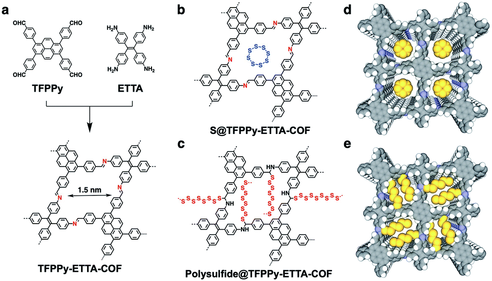 | ||
| Scheme 1 (a) Schematic of the synthesis of TFPPy–ETTA–COF. (b) Physical isolation of sulfur (S8 ring) in the COF. (c) Covalent engineering of polysulfide chains on the pore walls. (d) Graphic of S8 (yellow) loaded in S@TFPPy–ETTA–COF. (e) Graphic of polysulfide chains locked in polysulfide@TFPPy–ETTA–COF (one-layer polysulfide is shown for clarity; yellow; polysulfide). | ||
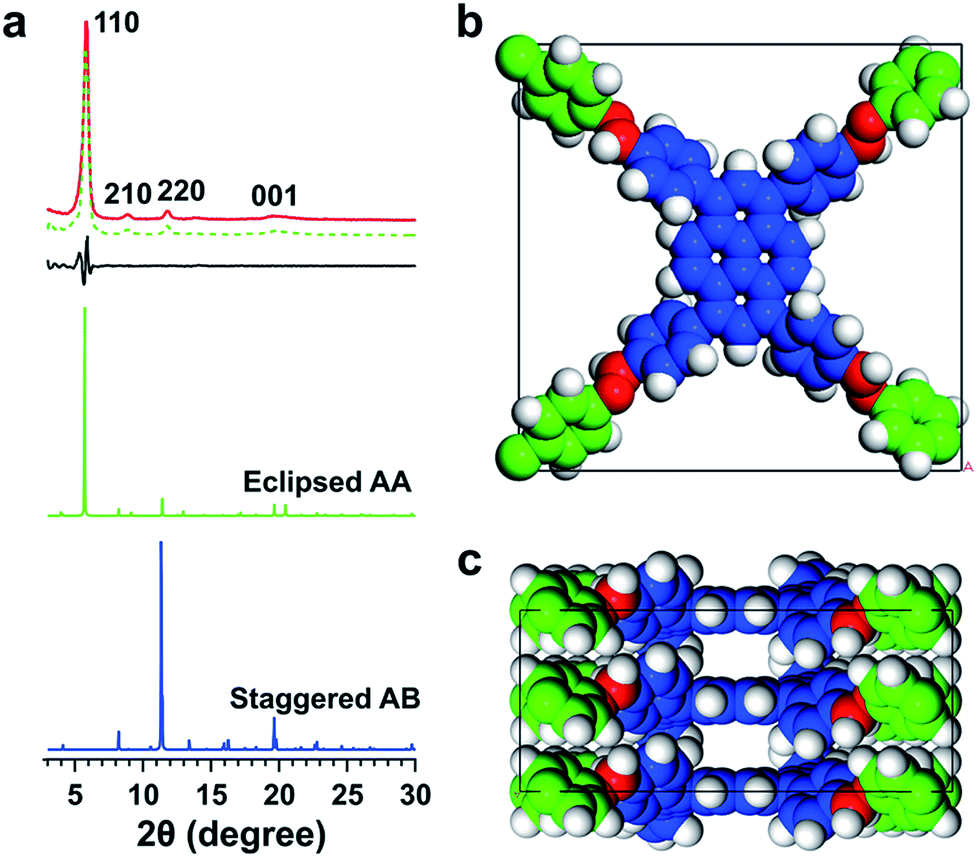 | ||
| Fig. 1 (a) PXRD patterns of TFPPy–ETTA–COF (red), the Pawley refinement (dotted green) and their difference (black), eclipsed AA (green), and AB (blue) stacking modes. (b) Top and (c) side views of the unit cell. | ||
Porosity
TFPPy–ETTA–COF is a microporous framework (Fig. 2a) with a Brunauer–Emmett–Teller (BET) surface area and a pore volume of 1223 m2 g−1 and 0.98 cm3 g−1, respectively. The pore size distribution profile revealed the presence of 1.5 nm-sized pores (Fig. 2b), which is identical to that of the lattice size. Moreover, the large meso- and macropores (Fig. 2b) were likely derived from interstitial sites of entangled nanofibers with a length of up to several micrometers and a diameter of 200 to 500 nm (Fig. S2†). Although scanning electron microscopy did not directly show such mesopores and macropores (inter-fiber space without a specific shape), the interstitial sites of entangled and intertwisted fibers would form these larger spaces (10–100 nm). A hierarchical porous structure is desired because the micropores ensure the confinement of sulfur or polysulfide chains, whereas the large pores allow for rapid ion delivery.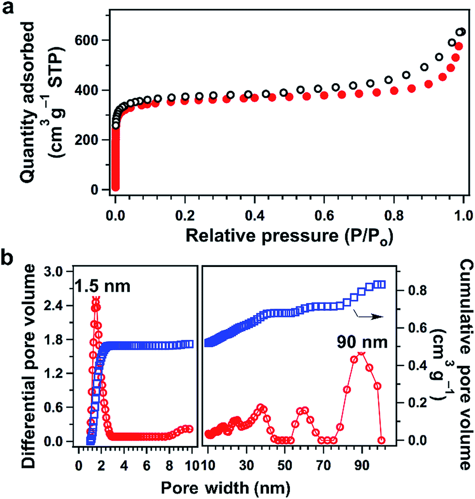 | ||
| Fig. 2 (a) Nitrogen sorption isotherms of TFPPy–ETTA–COF (filled circle: adsorption; open circle: desorption). (b) Pore-size distribution (red) and cumulative pore volume (blue) profiles. | ||
Engineering pore walls to anchor polysulfide chains
TFPPy–ETTA–COF exhibited outstanding thermal stability (Fig. 3a, black curve) and retained its crystalline (Fig. S3†) and chemical structures (Fig. S4†) up to even 430 °C under evacuated conditions. Polysulfide@TFPPy–ETTA–COF (Scheme 1c and e) was prepared by heating sulfur at 300 °C with TFPPy–ETTA–COF in which the CN imine units triggered the polymerization of sulfur to form polysulfide chains that are anchored on the pore walls via C–S bonds.16 Melting sulfur at 155 °C with the COF yielded S@TFPPy–ETTA–COF (Scheme 1b and d) with S8 loaded in the pores while the imine units are intact.
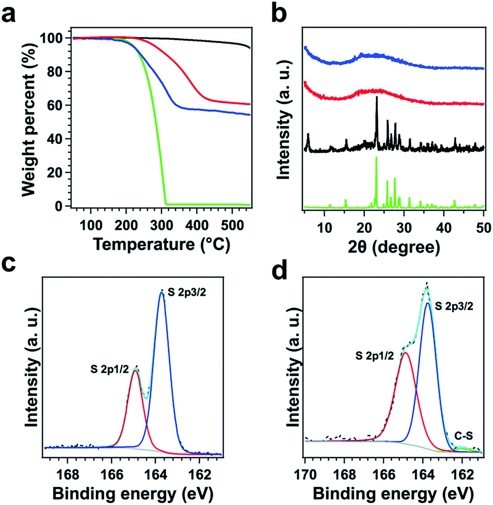 | ||
| Fig. 3 (a) TGA curves of TFPPy–ETTA–COF (black curve), polysulfide@TFPPy–ETTA–COF (red), S@TFPPy–ETTA–COF (blue), and sulfur (green). (b) PXRD patterns of S@TFPPy–ETTA–COF (blue), polysulfide@TFPPy–ETTA–COF (red), a simple mixture of TFPPy–ETTA–COF and sulfur (black), and elemental sulfur (green). The XPS S2p spectra of (c) S@TFPPy–ETTA–COF and (d) polysulfide@TFPPy–ETTA–COF. A clear C–S band was identified. | ||
Both COFs retained a nanofiber morphology with a uniform distribution of sulfur in the COFs (Fig. S2 and S5†). The disappeared crystalline sulfur peak (Fig. 3b) and decreased BET surface areas (Fig. S6 and Table S4†) indicated that the pores are occupied by polysulfide chains or S8. We washed the polysulfide@COF sample using CS2 solvent, collected the resulting solid and performed PXRD spectroscopy. The resulting solid exhibited a PXRD pattern with peak positions and relative intensities that are similar to these of TFPPy–ETTA–COF (Fig. S7†), indicating that the crystal structure of TFPPy–ETTA–COF is maintained in polysulfide@TFPPy–ETTA–COF, although polysulfide@TFPPy–ETTA–COF itself does not show any PXRD peaks. The sulfur and polysulfide chains in the pores are amorphous and they decrease the diffraction of the COF lattice. The S content was 42 wt% and 38 wt% for S@TFPPy–ETTA–COF and polysulfide@TFPPy–ETTA–COF, respectively (Fig. 3a). Owing to the covalent linkages, polysulfide@TFPPy–ETTA–COF exhibited an improved thermal stability compared to S@TFPPy–ETTA–COF (Fig. 3a and S8†).
The formation of polysulfide chains was investigated by Fourier-transform infrared (FT IR) and X-ray photoelectron spectroscopy (XPS). The CN peak at 1624 cm−1 found in TFPPy–ETTA–COF and S@TFPPy–ETTA–COF disappeared in polysulfide@TFPPy–ETTA–COF (Fig. 4), because the ring-opening of elemental sulfur with the diradical formed at elevated temperatures undergoes radical insertion reactions with the CN linkages.16 The red shift of the CC stretching vibration at 1500 cm−1 and the decreased intensity of the (–N–)C–H vibration at 1169 cm−1 in polysulfide@TFPPy–ETTA–COF indicate the substitution of H in (–N–)C–H by S. The C–S bond was observed by stretching bands at 690 and 1062 cm−1 (Fig. 4),17 and the S2p (162.1 eV for the C–S peak, Fig. 3c and d)15,18 and C1s (285.5 eV, Fig. S9†) peaks. The vibration band at 508 cm−1 was assigned to the S–S stretching of polysulfide chains (Fig. 4).17,19 These peaks were further supported by their similar XPS (Fig. S10†), FT IR spectra (Fig. S11†) and TGA (Fig. S12†) of a polysulfide@model compound. The recovered COF by washing polysulfide@TFPPy–ETTA–COF with CS2 shows an FT IR spectrum similar to that of polysulfide@TFPPy–ETTA–COF (Fig. S13†), suggesting that the polysulfide chains are chemically bonded to the pore walls. The polysulfide percentage was estimated to be 11 wt% based on the TGA measurements of polysulfide@TFPPy–ETTA–COF and the resulting solid sample upon washing with CS2 (Fig. S14†).
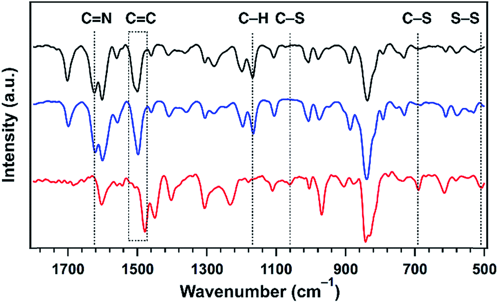 | ||
| Fig. 4 The FT IR spectra of TFPPy–ETTA–COF (black), S@TFPPy–ETTA–COF (blue), and polysulfide@TFPPy–ETTA–COF (red). | ||
Electrochemical kinetics and redox activities
Cyclic voltammetry (CV) revealed that polysulfide@TFPPy–ETTA–COF (Fig. 5a, red curve) has two sharp reduction peaks at 2.059 and 2.302 V; both of them yielded a higher current density than those (2.052 and 2.307 V) of S@TFPPy–ETTA–COF (blue curve), indicating an enhanced activity in reduction. Compared to S@TFPPy–ETTA–COF, a low potential in polysulfide@TFPPy–ETTA–COF suggests that the polysulfide chain is easy to be reduced to yield heavily lithiated polysulfide chains. In the charge process, polysulfide@TFPPy–ETTA–COF exhibited an oxidation peak at 2.388 V, which was higher in the current density and lower in the potential than those of S@TFPPy–ETTA–COF (2.405 V). Notably, compared to S@TFPPy–ETTA–COF (0.097 V), polysulfide@TFPPy–ETTA–COF exhibited a decreased peak separation (0.086 V), reflecting facilitated redox kinetics.12f Therefore, the polysulfide chains are capable of reversible lithiation and delithiation and show improved electrochemical kinetics and redox activities, compared to those of physically isolated sulfur. | ||
| Fig. 5 (a) CV profiles of S@TFPPy–ETTA–COF (blue) and polysulfide@TFPPy–ETTA–COF (red) at a scan rate of 0.1 mV s−1. (b) Charge–discharge profiles of polysulfide@TFPPy–ETTA–COF (red) and S@TFPPy–ETTA–COF (blue) at 0.1C. (c) Cycling performances and coulombic efficiency of polysulfide@TFPPy–ETTA–COF (red) and S@TFPPy–ETTA–COF (blue) over 100 cycles at 0.1C. | ||
Battery performance
Galvanostatic discharge–charge tests of polysulfide@TFPPy–ETTA–COF revealed two plateaus at 2.31 and 2.11 V during discharge and a continuous quasi-plateau from 2.23 to 2.35 V during charge (Fig. 5b, red curve). Each sample was evaluated with 3 cells to confirm the experimental reproducibility (Fig. S15†). Interestingly, polysulfide@TFPPy–ETTA–COF exhibited a long discharge/charge plateau to yield a high capacity of 1069 mA h g−1, which is 1.5 times as high as that (723 mA h g−1) of S@TFPPy–ETTA–COF (Fig. 5b). Considering the fact that only two polysulfide chains are integrated into one tetragonal macrocycle, this enhancement is remarkable. The sulfur accessibility of polysulfide@TFPPy–ETTA–COF reaches 64%, which is much higher than that (43%) of S@TFPPy–ETTA–COF. Therefore, the polysulfide chains can enhance not only capacity but also sulfur utilization efficiency.Surprisingly, these plateaus retained their shape upon cycling (Fig. S16†). The coulombic efficiency does not change during cycling (Fig. 5c). Notably, polysulfide@TFPPy–ETTA–COF is superior to S@TFPPy–ETTA–COF in terms of capacity over the whole cycle (Fig. 5c). The polysulfide@TFPPy–ETTA–COF sample consists of 11 wt% sulfur that is chemically bonded to the pore walls while the remaining sulfur in polysulfide@TFPPy–ETTA–COF is physically confined in the pores of COFs. Therefore, the initial quick loss of capacity is similar, as most sulfur is in the same form for both polysulfide@TFPPy–ETTA–COF and S@TFPPy–ETTA–COF. Nevertheless, polysulfide@TFPPy–ETTA–COF shows almost unchanged capacity after 60 cycles (Fig. S16b†), while S@TFPPy–ETTA–COF exhibits continuous fading upon cycling (Fig. S16a†). The capacity retention after 130 cycles is 99% (based on the capacity at the 60th cycle) and 54% (based on the capacity at the initial cycle) for polysulfide@TFPPy–ETTA–COF, which are both superior to 80% and 47% of S@TFPPy–ETTA–COF under the same conditions (Fig. S17†). Thus, the presence of chemically bonded polysulfide chains shows a positive yet great effect on cycle performance, as a result of decreased shuttle effects. The shuttle factor of the polysulfide@TFPPy–ETTA–COF electrode is 0.19, which is significantly lower than that (0.70) of the S@TFPPy–ETTA–COF electrode (ESI†). These results demonstrated that the chemically bonded polysulfide chains play a key role in energy storage.
We investigated the effect of polysulfide chains on the Li+ diffusion using the Randles–Sevcik equation via CV measurements at different sweeping rates (Fig. 6a and b, ESI Method†). Plots of the current versus the square root of the scan rate yielded a series of linear curves (Fig. 6d–f). Polysulfide@TFPPy–ETTA–COF exhibited diffusion coefficients of anodic DA1 = 3.55 × 10⁻⁸ cm2 s−1 (Fig. 6d, red dots), cathodic DC1 = 3.85 × 10⁻⁹ cm2 s−1 (Fig. 6e, red dots), and cathodic DC2 = 3.53 × 10⁻⁹ cm2 s−1 (Fig. 6f, red dots). These values are much higher than those of S@TFPPy–ETTA–COF (DA1 = 7.53 × 10⁻⁹ cm2 s−1 (Fig. 6d, blue dots), DC1 = 1.40 × 10⁻⁹ cm2 s−1 (Fig. 6e, blue curve), and DC2 = 1.36 × 10⁻⁹ cm2 s−1 (Fig. 6f, blue dots)). Thus, the polysulfide chains facilitate ion transport enhancement by 2.5–4.8 fold compared to S@TFPPy–ETTA–COF (Fig. S19†).
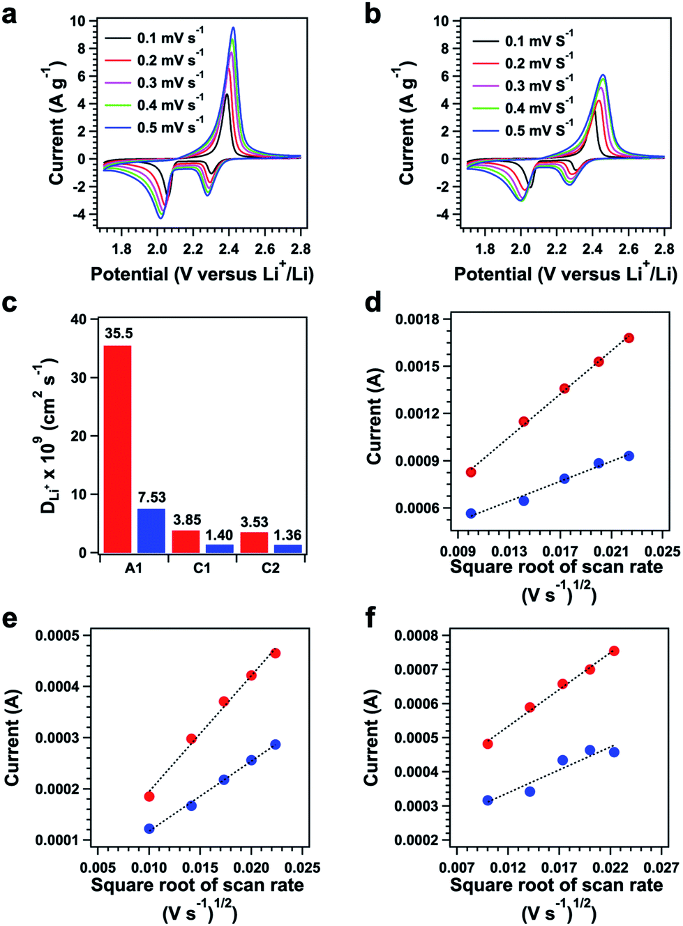 | ||
| Fig. 6 CV profiles of (a) polysulfide@TFPPy–ETTA–COF and (b) S@TFPPy–ETTA–COF at different scanning rates. (c) Li+ ion diffusion coefficients of polysulfide@TFPPy–ETTA–COF (red) and S@TFPPy–ETTA–COF (blue). The plots of current versus square root of the scanning rate of the (d) anodic peak (A1), (e) cathodic peak C1, and (f) cathodic peak C2 for polysulfide@TFPPy–ETTA–COF (red) and S@TFPPy–ETTA–COF (blue). | ||
Owing to the facilitated ion transport, polysulfide@TFPPy–ETTA–COF greatly improved rate performance (Fig. 7a, red curve). Reversible capacities of 698, 524, 414 and 347 mA h g−1 were achieved at 0.2, 0.5, 0.8 and 1C. The discharge and charge plateaus also demonstrated a reversible energy storage and power supply at different rates (Fig. 7b). In contrast, S@TFPPy–ETTA–COF (Fig. 7a, blue curve) suffers from the shuttle effect and delivers low capacities at various rates (Fig. S18†). When the current density is switched back to 0.2C, polysulfide@TFPPy–ETTA–COF achieves an 80.5% retention, which is also higher than the 75.8% retention of S@TFPPy–ETTA–COF (Fig. S19†). This effect also clearly indicates that the polysulfide chains are superior to sulfur in retaining the capacity. We further compared the retention of the same COF materials after long charge–discharge cycles. Polysulfide@TFPPy–ETTA–COF upon the final cycle at 0.2C achieves a capacity of 698 mA h g−1, which corresponds to an 88.6% retention compared to that of the initial 10 cycles at 0.2C. Under the same conditions, S@TFPPy–ETTA–COF has a capacity of 572 mA h g−1 with a retention of 85%.
 | ||
| Fig. 7 (a) Rate performances of polysulfide@TFPPy–ETTA–COF (red) and S@TFPPy–ETTA–COF (blue). (b) Charge–discharge curves of polysulfide@TFPPy–ETTA–COF at different rates. (c) Nyquist plots of polysulfide@TFPPy–ETTA–COF (red) and S@TFPPy–ETTA–COF (blue). | ||
Impedance spectra in Nyquist plots (Fig. 7c) revealed that both cathodes yielded two semicircles in a high-to-middle frequency range and a sloping line in the low frequency zone. The intercept at the real axis Z′ yielded the combination resistance R0 (Table S5†).20 By using an equivalent circuit, the resistance of ion transfer through the surface layer of the active material (Rs), charge transfer resistances (Rct), and the Warburg impedance (W0) were established (Fig. S20 and Table S5†). Apparently, polysulfide@TFPPy–ETTA–COF (Fig. 7c, red curve) exhibited much smaller Rct (56.2 Ω) and Rs (18.8 Ω) values than S@TFPPy–ETTA–COF (blue curve) (92.4 and 42.1 Ω for Rct and Rs, respectively). These results indicate that the polysulfide chains can accelerate charge conduction; a similar phenomenon has been shown for a polymer sulfur chain in carbon nanotubes.21 We measured the impedance spectra of these COFs after 11 cycles (Fig. S21†) and observed that both samples exhibited a decrement of resistivity, owing to the electrolyte penetration and electrode wetting. Notably, polysulfide@TFPPy–ETTA–COF exhibited a sharp drop in Rct from 56.2 to 33.1 Ω, which was greater than that (from 92.4 to 78.1 Ω) of S@TFPPy–ETTA–COF (Fig. S19†).
Conclusions
In summary, we have demonstrated that COFs offer a unique platform for addressing the shuttle issue by immobilizing the polysulfide chains on the pore walls. The integration of polysulfide chains transforms the electrochemically inert skeleton into energy storage frameworks. We disclosed for the first time the multifold positive effects of the polysulfide chains on redox reactions. In contrast to sulfur physically isolated in the nanochannels, the polysulfide chains fastened on the walls inhibit the shuttle effect, accelerate the redox kinetics and activity, facilitate ion transport, and improve charge conduction. These synergistic effects improve the overall performance. The resulting COFs achieve high sulfur efficiency, large capacity, high-rate performance and cycle stability – a set of important features that are highly desired for energy storage. Our strategy is simple as it is based on a post-synthetic engineering approach while it is also general as it is applicable to other imine-linked COFs with different topologies, skeletons and pore sizes. Therefore, the present work successfully demonstrates the great potential of COFs for addressing key issues in energy storage.Conflicts of interest
There are no conflicts to declare.Acknowledgements
D. J. appreciates the start-up grant of NUS (R-143-000-A28-133) and X. C. would like to acknowledge the research start-up fund from FZU for Minjiang Scholar Distinguished Professor (510760). This work was supported by the project of the National Natural Science Foundation of China (51702262, 51672225, and 51821091), the Creative Research Foundation of Science and Technology on Thermostructural Composite Materials Laboratory (6142911030512), and the project of China Postdoctoral Science Foundation (2018T111094 and 2018M643734).References
- (a) A. P. Côte, A. I. Benin, N. W. Ockwig, M. O'Keeffe, A. J. Matzger and O. M. Yaghi, Science, 2005, 310, 1166 CrossRef PubMed; (b) E. Jin, M. Asada, Q. Xu, S. Dalapati, M. A. Addicoat, M. A. Brady, H. Xu, T. Nakamura, T. Heine, Q. Chen and D. Jiang, Science, 2017, 357, 673 CrossRef CAS PubMed; (c) T. Ma, E. A. Kapustin, S. X. Yin, L. Liang, Z. Zhou, J. Niu, L. H. Li, Y. Wang, J. Su, J. Li, X. Wang, W. D. Wang, W. Wang, J. Sun and O. M. Yaghi, Science, 2018, 361, 48 CrossRef CAS PubMed; (d) A. M. Evans, L. R. Parent, N. C. Flanders, R. P. Bisbey, E. Vitaku, M. S. Kirschner, R. D. Schaller, L. X. Chen, N. C. Gianneschi and W. R. Dichtel, Science, 2018, 361, 52 CrossRef CAS PubMed; (e) X. Feng, X. Ding and D. Jiang, Chem. Soc. Rev., 2012, 41, 6010 RSC; (f) J. L. Segura, M. J. Mancheño and F. Zamora, Chem. Soc. Rev., 2016, 45, 5635 RSC; (g) N. Huang, P. Wang and D. Jiang, Nat. Rev. Mater., 2016, 1, 16068 CrossRef CAS; (h) C. S. Diercks and O. M. Yaghi, Science, 2017, 355, eaal1585 CrossRef PubMed; (i) S.-Y. Ding and W. Wang, Chem. Soc. Rev., 2013, 42, 548 RSC; (j) S. Das, P. Heasman, T. Ben and S. Qiu, Chem. Rev., 2018, 117, 1515 CrossRef PubMed.
- (a) C. J. Doonan, D. J. Tranchemontagne, T. G. Glover, J. R. Hunt and O. M. Yaghi, Nat. Chem., 2010, 2, 235 CrossRef CAS PubMed; (b) N. Huang, X. Chen, R. Krishna and D. Jiang, Angew. Chem., Int. Ed., 2015, 54, 2986 CrossRef CAS PubMed; (c) S. S. Han, H. Furukawa, O. M. Yaghi and W. A. Goddard, J. Am. Chem. Soc., 2008, 130, 11580 CrossRef CAS PubMed; (d) F. J. Uribe-Romo, J. R. Hunt, H. Furukawa, C. Klöck, M. O'Keeffe and O. M. Yaghi, J. Am. Chem. Soc., 2009, 131, 4570 CrossRef CAS PubMed; (e) C. Qian, Q. Qi, G. Jiang, F. Cui, Y. Tian and X. Zhao, J. Am. Chem. Soc., 2017, 139, 6736 CrossRef CAS PubMed; (f) T. Ben, C. Pei, D. Zhang, J. Xu, F. Deng, X. Jing and S. Qiu, Energy Environ. Sci., 2011, 4, 3991 RSC.
- (a) X. Hang, J. Huang, C. Yuan, Y. Liu and Y. Cui, J. Am. Chem. Soc., 2018, 140, 892 CrossRef PubMed; (b) H. Oh, S. B. Kalidindi, Y. Um, S. Bureekaew, R. Schmid, R. A. Fischer and M. Hirscher, Angew. Chem., Int. Ed., 2013, 52, 13219 CrossRef CAS PubMed; (c) C. Liu, E. Park, Y. Jin, J. Liu, Y. Yu, W. Zhang, S. Lei and W. Hu, Angew. Chem., Int. Ed., 2018, 57, 8984 CrossRef CAS PubMed.
- (a) N. Huang, L. Zhai, H. Xu and D. Jiang, J. Am. Chem. Soc., 2017, 139, 2428 CrossRef CAS PubMed; (b) Q. Sun, B. Aguila, J. Perman, L. D. Earl, C. W. Abney, Y. Cheng, H. Wei, N. Nguyen, L. Wojtas and S. Ma, J. Am. Chem. Soc., 2017, 139, 2786 CrossRef CAS PubMed; (c) S. Y. Ding, M. Dong, Y. Wang, Y. Chen, H. Wang, C. Su and W. Wang, J. Am. Chem. Soc., 2016, 138, 3031 CrossRef CAS PubMed; (d) Y. Ma, Z. Li, L. Wei, S. Y. Ding, Y. Zhang and W. Wang, J. Am. Chem. Soc., 2017, 139, 4995 CrossRef CAS PubMed.
- (a) S. Jin, X. Ding, X. Feng, M. Supur, K. Furukawa, S. Takahashi, M. Addicoat, M. E. El-Khouly, T. Nakamura, S. Irle, S. Fukuzumi, A. Nagai and D. Jiang, Angew. Chem., Int. Ed., 2013, 52, 2017 CrossRef CAS PubMed; (b) M. Dogru, M. Handloser, F. Auras, T. Kunz, D. Medina, A. Hartschuh, P. Knochel and T. Bein, Angew. Chem., Int. Ed., 2013, 52, 2920 CrossRef CAS PubMed.
- (a) H. Xu, J. Gao and D. Jiang, Nat. Chem., 2015, 7, 905 CrossRef CAS PubMed; (b) S. Lu, Y. Hu, S. Wan, R. McCaffrey, Y. Jin, H. Gu and W. Zhang, J. Am. Chem. Soc., 2017, 139, 17082 CrossRef CAS PubMed; (c) S. Y. Ding, J. Gao, Q. Wang, Y. Zhang, W. Song, C. Su and W. Wang, J. Am. Chem. Soc., 2011, 133, 19816 CrossRef CAS PubMed; (d) X. Han, Q. Xia, J. Huang, Y. Liu, C. Tan and Y. Cui, J. Am. Chem. Soc., 2017, 139, 8693 CrossRef CAS PubMed; (e) P. Wei, M. Qi, Z. Wang, S. Y. Ding, W. Yu, Q. Liu, L. Wang, H. Wang, W. An and W. Wang, J. Am. Chem. Soc., 2018, 140, 4623 CrossRef CAS PubMed.
- (a) S. Chandra, T. Kundu, S. Kandambeth, R. BabaRao, Y. Marathe, S. M. Kunjir and R. Banerjee, J. Am. Chem. Soc., 2014, 136, 6570 CrossRef CAS PubMed; (b) H. Ma, B. Liu, B. Li, L. Zhang, Y. Li, H. Tan, H. Zang and G. Zhu, J. Am. Chem. Soc., 2016, 138, 5897 CrossRef CAS PubMed; (c) H. Xu, S. Tao and D. Jiang, Nat. Mater., 2016, 15, 722 CrossRef CAS PubMed.
- (a) S. Dalapati, S. Jin, J. Gao, Y. Xu, A. Nagai and D. Jiang, J. Am. Chem. Soc., 2013, 135, 17310 CrossRef CAS PubMed; (b) Y. Peng, Y. Huang, Y. Zhu, B. Chen, L. Wang, Z. Lai, Z. Zhang, M. Zhao, C. Tan, N. Yang, F. Shao, Y. Han and H. Zhang, J. Am. Chem. Soc., 2017, 139, 8698 CrossRef CAS PubMed.
- (a) T. Sick, A. G. Hufnagel, J. Kampmann, I. Kondofersky, M. Calik, J. M. Rotter, A. Evans, M. Doblinger, S. Herbert, K. Peters, D. Bohm, P. Knochel, D. D. Medina, D. Fattakhova-Rohlfing and T. Bein, J. Am. Chem. Soc., 2018, 140, 2085 CrossRef CAS PubMed; (b) P. P. Pachfule, A. Acharjya, J. Roeser, T. Langenhahn, M. Schwarze, R. Schomacker, A. Thomas and J. Schmidt, J. Am. Chem. Soc., 2018, 140, 1423 CrossRef CAS PubMed; (c) V. S. Vyas, F. Haase, L. Stegbauer, G. Savasci, F. Podjaski, C. Ochsenfeld and B. V. Lotsch, Nat. Commun., 2015, 6, 8508 CrossRef CAS PubMed.
- (a) F. Xu, S. Jin, H. Zhong, D. Wu, X. Yang, X. Chen, H. Wei, R. Fu and D. Jiang, Sci. Rep., 2015, 5, 8225 CrossRef CAS PubMed; (b) F. Xu, H. Xu, X. Chen, D. Wu, Y. Wu, H. Liu, C. Gu, R. Fu and D. Jiang, Angew. Chem., Int. Ed., 2015, 54, 6814 CrossRef CAS PubMed; (c) C. R. DeBlase, K. E. Silberstein, T. T. Truong, H. D. Abruna and W. R. Dichtel, J. Am. Chem. Soc., 2013, 135, 16821 CrossRef CAS PubMed; (d) S. Wang, Q. Wang, P. Shao, Y. Han, X. Gao, L. Ma, S. Yuan, X. Ma, J. Zhou, X. Feng and B. Wang, J. Am. Chem. Soc., 2017, 139, 4258 CrossRef CAS PubMed; (e) X. Wu, Y. Liu, H. Liu, C. Duan, Q. Pan, J. Zhu, F. Hu, X. Ma, T. Jiu, Z. Li and Y. Zhao, J. Am. Chem. Soc., 2018, 140, 10016 CrossRef PubMed; (f) C. R. Mulzer, L. Shen, R. P. Bisbey, J. R. McKone, N. Zhang, H. D. Abruña and W. R. Dichtel, ACS Cent. Sci., 2016, 2, 667 CrossRef CAS PubMed.
- Q. Sun, C. Fu, B. Aguila, J. Perman, S. Wang, H. Huang, F. Xiao and S. Ma, J. Am. Chem. Soc., 2018, 140, 984 CrossRef CAS PubMed.
- (a) H. Liao, H. Wang, H. Ding, X. Meng, H. Xu, B. Wang, X. Ai and C. Wang, J. Mater. Chem. A, 2016, 4, 7416 RSC; (b) S. N. Talapaneni, T. H. Hwang, S. H. Je, O. Buyukcakir, J. W. Choi and A. Coskun, Angew. Chem., Int. Ed., 2016, 55, 3106 CrossRef CAS PubMed; (c) X. Yang, B. Dong, H. Zhang, R. Ge, Y. Gao and H. Zhang, RSC Adv., 2015, 5, 86137 RSC; (d) Z. A. Ghazi, L. Zhu, H. Wang, A. Naeem, A. M. Khattak, B. Liang, N. A. Khan, Z. Wei, L. Li and Z. Tang, Adv. Energy Mater., 2016, 6, 1601250 CrossRef; (e) H. Liao, H. Ding, B. Li, X. Ai and C. Wang, J. Mater. Chem. A, 2014, 2, 8854 RSC; (f) F. Xu, S. Yang, G. Jiang, Q. Ye, B. Wei and H. Wang, ACS Appl. Mater. Interfaces, 2017, 9, 37731 CrossRef CAS PubMed.
- (a) P. G. Bruce, S. A. Freunberger, L. J. Hardwick and J.-M. Tarascon, Nat. Mater., 2012, 11, 19 CrossRef CAS PubMed; (b) Z. W. Seh, Y. Sun, Q. Zhang and Y. Cui, Chem. Soc. Rev., 2016, 45, 5605 RSC.
- W. J. Chung, J. J. Griebel, E. T. Kim, H. Yoon, A. G. Simmonds, H. J. Ji, P. T. Dirlam, R. S. Glass, J. J Wie, N. A. Nguyen, B. W. Guralnick, J. Park, A. Somogyi, P. Theato, M. E. Mackay, Y. E. Sung, K. Char and J. Pyun, Nat. Chem., 2013, 5, 518 CrossRef CAS PubMed.
- H. Kim, J. Lee, H. Ahn, O. Kim and M. J. Park, Nat. Commun., 2015, 6, 7278 CrossRef CAS PubMed.
- (a) W. Zhou, Y. Yu, H. Chen, F. J. DiSalvo and H. D. Abruna, J. Am. Chem. Soc., 2013, 135, 16736 CrossRef CAS PubMed; (b) F. Haase, E. Troscheke, G. Savasci, T. Banerjee, V. Duppel, S. Dörfler, M. M. J. Grundei, A. M. Burow, C. Ochsenfeld, S. Kaskel and B. V. Lotsch, Nat. Commun., 2018, 9, 3933 CrossRef PubMed.
- X. Yu, J. Xie, J. Yang, H. Huang, K. Wang and Z. Wen, J. Electroanal. Chem., 2004, 573, 121 CAS.
- G. Hu, Z. Sun, C. Shi, R. Fang, J. Chen, P. Hou, C. Liu, H. Cheng and F. Li, Adv. Mater., 2017, 29, 1603835 CrossRef PubMed.
- X. Yu, J. Xie, Y. Li, H. Huang, C. Lai and K. Wang, J. Power Sources, 2005, 146, 335 CrossRef CAS.
- Z. Li, C. Li, X. Ge, J. Ma, Z. Zhang, Q. Li, C. Wang and L. Yin, Nano Energy, 2016, 23, 15 CrossRef CAS.
- T. Fujimori, A. Morelos-Gomez, Z. Zhu, H. Muramatsu, R. Futamura, K. Urita, M. Terrones, T. Hayashi, M. Endo, S. Y. Hong, Y. C. Choi, D. Tomanek and K. Kaneko, Nat. Commun., 2013, 4, 2162 CrossRef PubMed.
Footnote |
| † Electronic supplementary information (ESI) available: Materials and methods, synthetic procedures, Tables S1–S5, and Fig. S1–S21. See DOI: 10.1039/c8sc04518f |
| This journal is © The Royal Society of Chemistry 2019 |