
 Open Access Article
 This Open Access Article is licensed under a Creative Commons Attribution-Non Commercial 3.0 Unported Licence
Ionic organic cage-encapsulating phase-transferable metal clusters†
Su-Yun
Zhang
 a,
Zdravko
Kochovski
c,
Hui-Chun
Lee
a,
Yan
Lu
cd,
Hemin
Zhang
e,
Jie
Zhang
a,
Jian-Ke
Sun
*a and
Jiayin
Yuan
*b
a,
Zdravko
Kochovski
c,
Hui-Chun
Lee
a,
Yan
Lu
cd,
Hemin
Zhang
e,
Jie
Zhang
a,
Jian-Ke
Sun
*a and
Jiayin
Yuan
*b
aMOE Key Laboratory of Cluster Science, Beijing Key Laboratory of Photoelectronic/Electrophotonic Conversion Materials, School of Chemistry and Chemical Engineering, Beijing Institute of Technology, Beijing, P. R. China. E-mail: jiankesun15@gmail.com
bDepartment of Materials and Environmental Chemistry, Stockholm University, 10691 Stockholm, Sweden. E-mail: jiayin.yuan@mmk.su.se
cSoft Matter and Functional Materials, Helmholtz-Zentrum Berlin für Materialien und Energie, 14109 Berlin, Germany
dInstitute of Chemistry, University of Potsdam, 14467 Potsdam, Germany
eSchool of Energy and Chemical Engineering, Ulsan National Institute of Science & Technology (UNIST), Ulsan 689-798, Republic of Korea
First published on 19th November 2018
Abstract
Exploration of metal clusters (MCs) adaptive to both aqueous and oil phases without disturbing their size is promising for a broad scope of applications. The state-of-the-art approach via ligand-binding may perturb MCs' size due to varied metal–ligand binding strength when shuttling between solvents of different polarity. Herein, we applied physical confinement of a series of small noble MCs (<1 nm) inside ionic organic cages (I-Cages), which by means of anion exchange enables reversible transfer of MCs between aqueous and hydrophobic solutions without varying their ultrasmall size. Moreover, the MCs@I-Cage hybrid serves as a recyclable, reaction-switchable catalyst featuring high activity in liquid-phase NH3BH3 (AB) hydrolysis reaction with a turnover frequency (TOF) of 115 min−1.
Introduction
Metal clusters (MCs) are particles of <2 nm in size and exhibit intrinsic size-dependent properties, such as discrete electronic structures, intense photoluminescence, high catalytic activity (such as oxidation, hydrogenation, and coupling reactions), etc.1 Synthesis of MCs capable of adapting both aqueous and organic phases is favorably pursued because of a broader scope of operational environment.2 MCs, especially of size <1 nm practically carry all constitutional atoms on their surface, and possess a higher specific surface energy than the exhaustively explored larger metal nanoparticles (MNPs).3 Thus they aggregate more severely without sufficient protection in solutions.4,5 Synthetic methods of MCs are so far dominated by the surface-binding ligand approach, including amphiphilic capping agents, and the oil–water phase transfer agents by either ligand exchange or modification.2,6 A challenge associated with the ligand approaches that relies on binding active sites of MCs is that the MC core is labile and prone to size variation due to altered metal–ligand binding strength upon ligand exchange or modification.7 In addition, these approaches suffer from a trade-off, i.e. binding a high-energy, catalytically active surface by polar groups of ligands restricts accessibility of reactants to these active sites during catalysis.8 In this regard, a stabilization mechanism of MCs majorly by physical confinement and partially by surface binding would allow MCs to maintain their high catalytic activity in different solvents with little-to-no perturbation of stabilization, thus possibly breaking the trade-off.Organic molecular cages are an emerging class of multifunctional materials featuring a discrete pore structure.9 They are molecularly soluble and possess a wide spectrum of properties and functions due to their designable molecular architecture and intrinsic open channels. A unique merit of cages is to accommodate guest objects, such as MCs/MNPs without blocking much of their active surface sites and to “solubilize” them in liquid-phase for catalysis.10
Herein, we utilized ionic organic cages to synthesize and confine a series of well-dispersed, water–oil phase adaptive noble MCs of 0.5–0.7 nm in size (Scheme 1). Different from MCs reported previously that have limited choices of metal species and/or solvents, our example improves compatibility between the ionic cage molecule and metal species. More significantly, the highly charged cage (+12 per cage) can trap metal anion precursor to control MC growth and avoid spontaneously aggregation by electrostatic repulsion. The MCs confined in I-Cage experience anion-controlled reversible water–oil phase transfer without size perturbation. Such MC@I-Cage hybrid was explored as recyclable/switchable catalyst11 with high activity in a liquid-phase H2 release reaction.
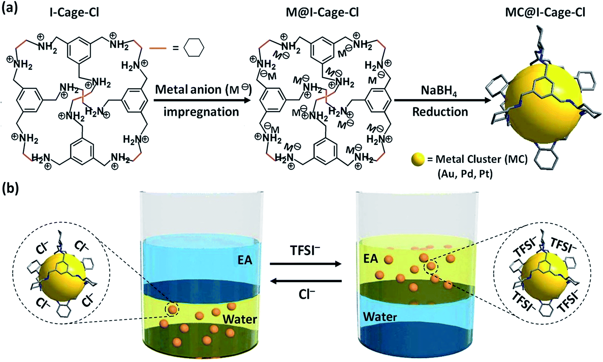 | ||
| Scheme 1 (a) Synthetic scheme of MCs stabilized by I-Cage–Cl (Cl as counterion) in an aqueous phase (for clarity reasons Cl− anions are omitted; M− = [AuCl4]−, [PdCl4]2− and [PtCl4]2−). (b) Anion exchange-driven phase transfer of I-Cage–X (X = Cl− or TFSI−, TFSI = bis(trifluoromethane sulfonyl)imide)-capped MCs between aqueous and ethyl acetate (EA) phases. | ||
Experimental
Materials and methods
All chemicals were obtained from commercial sources and used without further purification. Conventional transmission electron microscopy (TEM) was performed on a JEOL 2010FS transmission electron microscope operated at 120 kV. The scanning TEM (STEM) was performed on a Jeol JEM-2200FS transmission electron microscope operated at 200 kV and equipped with a high-angle annular dark-field (HAADF) STEM detector. The cryogenic electron microscopy (Cryo-EM) was performed on a JEOL JEM-2100 transmission electron microscope (JEOL GmbH, Eching, Germany). Cryo-EM specimens were prepared by applying a 4 μL drop of a dispersion sample to Lacey carbon-coated copper TEM grids (200 mesh, Science Services) and plunge-frozen into liquid ethane with an FEI vitrobot Mark IV set at 4 °C and 95% humidity. Vitrified grids were either transferred directly to the microscope cryogenic transfer holder (Gatan 914, Gatan, Munich, Germany) or stored in liquid nitrogen. Imaging was carried out at temperatures around 90 K. The TEM was operated at an acceleration voltage of 200 kV, and a defocus of the objective lens of about 2.5–3 μm was used to increase the contrast. Cryo-EM micrographs were recorded at a number of magnifications with a bottom-mounted 4 × 4k CMOS camera (TemCam-F416, TVIPS, Gauting, Germany). The total electron dose in each micrograph was kept below 20 e− Å−2. X-ray photoelectron spectroscopy (XPS) studies were performed on a ThermoFisher ESCALAB250 X-ray photoelectron spectrometer (powered at 150 W) using Al Kα radiation (λ = 8.357 Å). To compensate surface charging effects, the XPS spectrum was referenced to the C 1s neutral carbon peak at 284.6 eV. The solution UV-Vis absorption measurements were recorded on a Lambda 900 spectrophotometer. 1H and 13C nuclear magnetic resonance (1H-NMR and 13C-NMR) measurements were carried out at room temperature on a Bruker ascend-400/600 spectrometer in D2O and CDCl3. Dynamic light scattering (DLS) was performed on a NICOMP particle sizer (model 380 PSS, Santa Barbara, CA). Zeta potential measurement was performed on Zetasizer Nano ZS90 (Malvern). Electrospray ionisation mass spectrometry (ESI-MS) was performed on 1200 Series & HCT Basic System (Bruker). Inductively coupled plasma optical emission spectrometry (ICP-OES) was performed on Varian 700-ES (Agilent), calibrated with standard solutions.Synthesis of porous cycloimine cage molecule CC3
The synthesis of CC3 was conducted according to a previous method.10a A typical procedure is as follows: CH2Cl2 (10 mL) was added slowly to solid 1,3,5-triformylbenzene (0.5 g) at room temperature. Trifluoroacetic acid (10 μL) was added directly to this solution as a catalyst for imine bond formation. Finally, a CH2Cl2 solution (10 mL) of (R,R)-1,2-diaminocyclohexane (0.5 g, 4.464 mmol) was added. The vessel of the mixture solution was capped and left to stand for one week. Crystals grew on the sides of the vessel. The crystalline product was removed by centrifugation and washed with CH2Cl2/CH3OH mixture (v/v, 5/95) for several times, and further dried at 100 °C overnight. The 1H NMR spectrum is consistent with reported CC3 (Fig. S36†).Synthesis of reduced CC3 (RCC3)
The synthesis of RCC3 was conducted according to a previous method.12a,c The imine cage CC3 (463 mg) was dissolved in a CH2Cl2/CH3OH mixture (v/v, 1/1, 25 mL) by stirring. When this solution became clear, NaBH4 (0.5 g) was added and the reaction was stirred for 15 h at room temperature. Water (1 mL) was then added, and the solution was continuously stirred for additional 9 h. The solvent was then removed under vacuum. The resulted solid was washed by water and collected by centrifugation, and the obtained solid was dried at 80 °C under vacuum overnight. The 1H NMR spectrum is consistent with reported RCC3 (Fig. S37†).Synthesis of I-Cage–Cl12b
RCC3 (500 mg) was dissolved in CHCl3 (10 mL) by stirring. Hydrogen chloride (in dioxane, 2.50 mL) was added dropwise. The precipitate appeared and the reaction mixture was stirred for a further 2 h at room temperature. The precipitate was collected by filtration then washed by CHCl3 for several times to give solid powder after being dried under vacuum at 90 °C. 1H NMR (D2O, 400 MHz) δ 7.62 (s, 12H, –ArH), 4.47 (d, 12H, –ArCH2), 4.23 (d, 12H, –ArCH2), 3.69 (d, 12H, CH on cyclohexane), 2.55–1.27 (m, 48H, CH2 on cyclohexane) ppm (the details of peak integration are shown in Fig. S38†); 13C NMR (D2O, 400 MHz): δ 133.0, 130.0, 58.5, 48.3, 25.8, 22.6 ppm. The reported RCC3 formula is C72H108N12 (M = 1141.73),12a accordingly, the estimated molecular formula for cationic cage part is C72H120N12 (the 12 –NH– units per cage are fully protonated by acid, M = 1154). This is consistent with the ESI(+)-MS analysis result [M + H]+ of 1155.5 (Fig. S3†).Synthesis of metal cluster (MC)/metal nanoparticles stabilized by different supports
Phase transfer of Au@I-Cage–X (X = Cl− or TFSI−) driven by anion exchange
Typically, 1 mL of as-synthesized Au@I-Cage–Cl (above section) was layered with 1 mL ethyl acetate (EA), then 3 mg LiTFSI was added into the solution and rigorously shaking to let Au@I-Cage–Cl transfer to EA (Au@I-Cage–TFSI) (the addition of a few drop of methanol (∼50 μL) that is miscible in both water and EA can accelerate the transfer process). Then 6 mg KCl was added into the solution to achieve the reversible transfer to water solution.Synthesis of catalyst for AB hydrolysis reaction
Catalytic activity characterization
| NH3BH3 +2H2O → NH4BO2 + 3H2 | (1) |
Results and discussion
The targeted ionic cage molecule (denoted as I-Cage–Cl, Cl as counterion), [(H12RCC3)12+12Cl−], was synthesized according to a recent report by HCl-acidifying a neutral amine cage RCC3 (Scheme S1†).12a,b Each I-Cage–Cl carries 12 cations and was characterized by 1H and 13C NMR spectra and mass spectrometry (Fig. S1–S3†). The hydrophilic ammonium chloride ion pair makes I-Cage–Cl readily water-soluble, while its neutral precursor RCC3 is insoluble. The cryo-EM image (Fig. S4†) of I-Cage–Cl reveals well-dispersed dark dots of 3 ± 0.4 nm in size, slightly larger than its precursor RCC3 of ∼2 nm in size (cryo-EM image in Fig. S5,† which is in agreement with size estimation from its octahedron architecture12b). The size expansion from RCC3 to I-Cage–Cl is expected as the ionized –NH– units electrostatically stretch the cage and the newly introduced Cl− also expand its overall hydrodynamic size.Due to a high cation density on the cage, the coulombic attraction and the confinement effect facilitate encapsulation of metal anions into I-Cage–Cl as host, as reported recently for a host of metals on different supports.13 Principally, the reduction of encapsulated metal anions and the subsequent nucleation within the cage host is expected and downsizes MCs to match the cage cavity. Experimentally this process runs as follows: a pale yellow solution of I-Cage–Cl (15 mg) in 9 mL of water was prepared. It became light brown upon addition of HAuCl4 (Au content: 0.5 mg). The interaction between the cationic cage and [AuCl4]− was monitored by zeta potential analysis, in which an initial value of +38.9 mV of I-Cage–Cl drops to +28.6 mV upon addition of HAuCl4 due to specific adsorption/complexation of [AuCl4]− by I-Cage–Cl. Addition of NaBH4 at r.t. produced a pale brown, stable MC solution.
DLS study (Fig. S6†) and cryo-EM analysis (Fig. 1a) determine the as-synthesized Au@I-Cage–Cl be to 3.0 nm and 3.1 ± 0.4 nm, respectively, in good consistence with the size value of native I-Cage–Cl. The size of Au clusters was determined by high-angle annular dark-field scanning transmission electron microscopy (HAADF-STEM) to be 0.65 ± 0.2 nm (Fig. 1b and S7a†), which matches well with the pore size of RCC3 cage (∼0.72 nm), indicative of possibility of cage encapsulation. Such small cluster size agrees well with the absence of a Plasmon peak in the UV-Vis spectrum (Fig. 2b). XPS data identify peaks of binding energy at 88.4 and 84.4 eV, corresponding to 4f5/2 and 4f7/2 of metallic Au existed in the cage (Fig. S8†).
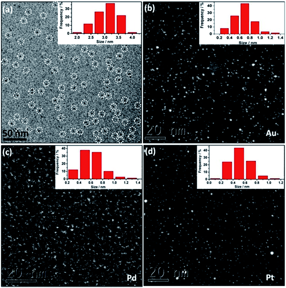 | ||
| Fig. 1 (a) Cryo-EM image of Au@I-Cage–Cl on a Lacey carbon grid and the size distribution histogram. Some Au@I-Cage–Cl are highlighted by white dotted circles. (b–d) HAADF-STEM images and the size distribution histograms of Au, Pd and Pt clusters, respectively. | ||
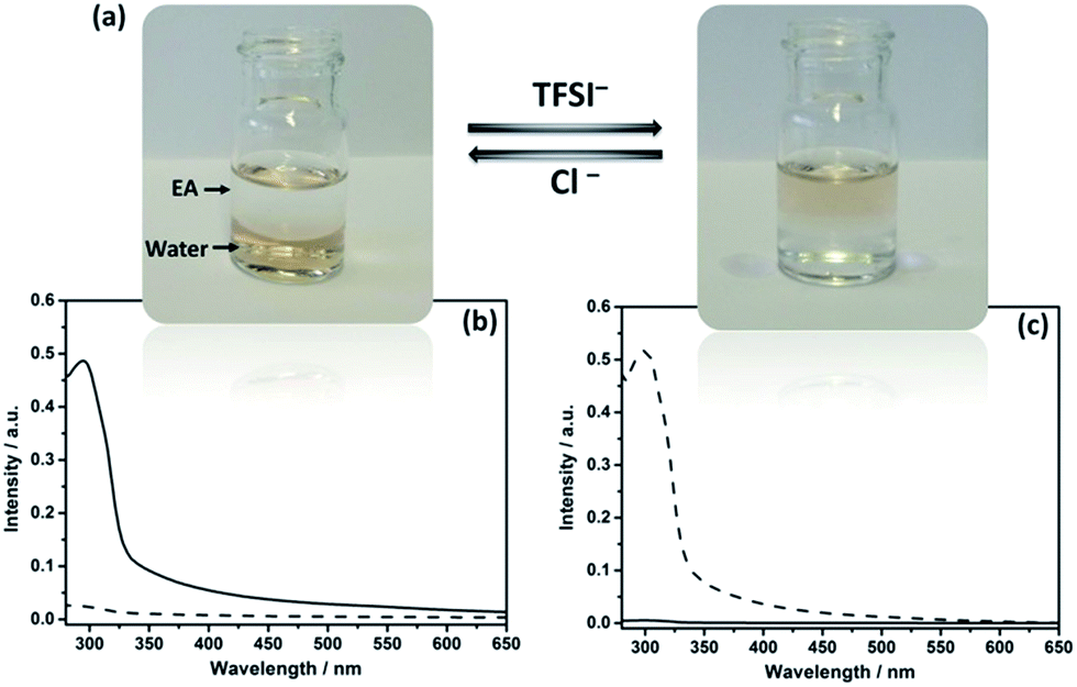 | ||
| Fig. 2 (a) Photographs showing reversible transfer of Au–I-Cage–X (X = Cl− or TFSI−) between aqueous and EA phases upon anion exchange. (b and c) UV-Vis spectra of Au clusters transferred between aqueous and EA phases (solid curve for aqueous phase, dotted curve for EA phase) as shown in (a). | ||
The NMR technique is applied to better analyze Au@I-Cage–Cl and specifically, the spatial relationship between the cage host and the Au cluster guest. The 13C NMR spectra of Au@I-Cage–Cl (Fig. S2b†) and I-Cage–Cl (Fig. S2a†) show little-to-no variation in peak positions, suggesting that I-Cage–Cl is in an approximate configuration before and after encapsulation of MCs. Interestingly, in comparison to I-Cage–Cl (Fig. S1a†), broadening of all peak widths in the 1H NMR spectrum of Au@I-Cage–Cl (Fig. S1b†) is observed, indicative of a local restricted motion and structural heterogeneity stemming from encapsulation of Au clusters.14,12c A similar observation was reported in Au NPs@Cage (average Au NP size: 1.9 nm),14a in which the cage shell tightly wrapped around the AuNP, and experienced restricted mobility and fast spin relaxation. Further evidence was given by 2D diffusion ordered spectroscopy 1H nuclear magnetic resonance (2D DOSY 1H NMR) (Fig. S9 and S10†) that shows similar diffusion coefficients for Au@I-Cage–Cl (2.16 × 10⁻⁶ cm2 s−1) and I-Cage–Cl (2.06 × 10⁻⁶ cm2 s−1), confirming the similar size and shape of native I-Cage–Cl and Au@I-Cage–Cl. Such observation proves that Au clusters rest inside the cage cavity instead of intercage interactions or aggregation on the cage surface.14a,12c In addition, the size of Au@I-Cage–Cl determined by cryo-EM data in Fig. 1a and DLS (consistent with single native I-Cage–Cl cage) excludes the possibility of Au clusters stabilized by multiple cages.
Cage-confinement brings Au clusters high stability. For example, storage in a temperature range from 77 to 363 K and in a pH range from 3 to 10 did not change the cluster size, as confirmed by UV-Vis spectra (Fig. S11†) and HAADF-STEM analysis (Fig. S12–S15†). Rationally the electrostatic repulsion separates molecular cages and each octahedron cage sterically contains individual MCs well inside.15 In a control experiment without I-Cage–Cl, only aggregated Au NPs were observed (Fig. S16†). Using neutral cage RCC3 as support produced Au NPs of a larger size of 4 ± 0.8 nm with a broader size distribution and poor solubility in water (Fig. S17†). Moreover, a monovalent ionic liquid (IL) 4-cyanomethyl-1-vinyl-imidazolium bromide, when used in the same experiment, resulted in Au NPs of 6 ± 0.9 nm in size (Fig. S18†). Therefore, the cage-ion synergy plays a pivotal role in size control. It is worth noting that our method can produce other noble MCs, i.e. 0.6 ± 0.2 nm for Pd (Fig. 1c and S7b†) and 0.5 ± 0.2 nm for Pt clusters (Fig. 1d and S7c†).
In IL chemistry, hydrophilicity/hydrophobicity of ILs is switchable by ion metathesis.16 Here, as a proof of concept, Au@I-Cage–Cl was modified into hydrophobic Au@I-Cage–TFSI bearing bis(trifluoromethane sulfonyl)imide (TFSI) anion by anion exchange17 with LiTFSI (Scheme 1b). Experimentally, hydrophobic ethyl acetate (EA) was first added to a pale brown Au@I-Cage–Cl aqueous solution to form a clear supernatant. Addition of LiTFSI formed a colorless aqueous phase and a pale brown EA phase (Fig. 2a). Residue Au@I-Cage–Cl in the aqueous phase produced a negligible absorbance peak at λ = 300 nm (assigned to I-Cage) in its UV-Vis spectrum, while the EA phase shows a characteristic absorbance spectrum of I-Cage, indicative of a quantitative phase transfer (Fig. 2c). A similar behavior was observed when Au clusters were reversed to aqueous phase by adding KCl (Fig. 2b). ICP-OES measurement shows <5 ppm loss of Au (Fig. S19†) during this cycle, indicative of its reversible nature. Such process can be repeated two times without significantly altering the intensity and position of cage peak in UV-Vis spectrum (Fig. S20†). Additionally, DLS (Fig. S21†), cryo-EM (Fig. S22†) and HAADF-STEM analyses did not show any size increase (Fig. S23a–c†) for Au cluster, as also for Pd and Pt (Fig. S23d–i, S24 and S25†). Worth to mention is that such feature is valuable, as it combines the physical confinement effect with ion exchange capability, which fails in conventional organic ligands.
Being physically confined and phase transferable is useful, as it allows the same MC catalyst for operations in different liquids while strictly keeping their size. Tested in a H2 release reaction by hydrolysis of AB compound,18 Pt@I-Cage–Cl at a Pt loading content of 0.01 mmol (Pt/AB = 0.02) completed the reaction (H2/AB = 3.0) within 1.3 min at 300 K (Fig. 3 and S26†). The turnover frequency (TOF) is 115 min−1, which is much higher than conventional surfactant-protected catalysts (Fig. S27–S30†), e.g. Pt/CTAB (2.7 ± 0.3 nm, TOF: 5 min−1), Pt/PVP (4 ± 0.4 nm, TOF: 13 min−1), and RCC3-supported Pt NPs (Pt/RCC3, 3 ± 0.6 nm, TOF: 30 min−1) (Fig. S31 and 32†), and comparable to the reported highly active monometallic Pt cluster/nanoparticle catalysts.19 Not surprising, a low TOF value of 20 min−1 was found for cage-free Pt nanoparticles (Pt-SP-Free) (Fig. 3 and S33†). Although I-Cage–Cl itself is catalytically inactive to AB (tested in Fig. S34†), the discrete open structure can promote catalytic reactions by downsizing Pt clusters and maximizing metal–reactant contact in solution.
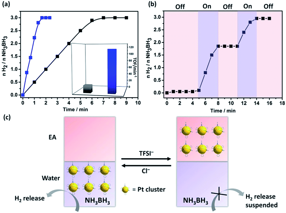 | ||
| Fig. 3 (a) Time course plots of H2 generation for the hydrolysis of ammonia borane (AB) over the Pt@I-Cage–Cl (blue line) and unsupported Pt catalysts, Pt-SP-Free (dark line) at 300 K (Pt/AB = 0.02). Inset: the corresponding TOF values. (b) Control of H2 release in the AB hydrolysis in water–EA mixture (pink and violet regions for “off” and “on” state, respectively). (c) Diagram of controlled H2 release process. | ||
The phase-transfer process is useful to recover and recycle catalyst. Typically, after completion of a reaction, Pt clusters were transferred to the EA phase by LiTFSI. The impure aqueous phase was replaced by clean water, before Pt clusters moved back by adding KCl for the next run (Fig. S35†). Uniquely, the anion exchange could regulate the H2 production. As shown in Fig. 3b and c, H2 generation was stopped upon addition of LiTFSI to evacuate Pt clusters from water; the reaction re-started by adding KCl to transfer Pt clusters back. This “on”/“off” cycle can be repeated till AB is consumed. Our system provides a new insight toward kinetic control for on-demand H2 release in practical use.
Conclusions
In conclusion, a method to prepare sub-nano-sized noble MCs hosted by an ionic organic cage was reported. The reversible anion exchange process enables confined MCs to be shuttled selectively between an aqueous and an organic phase, which allows for efficient separation and recycling of MC catalysts from products or reaction mixtures. This method will equip researchers with a new tool to engineer MCs without compromising their catalytic activity, thus improving and augmenting applications in different research areas.Conflicts of interest
There are no conflicts to declare.Acknowledgements
J. Y. acknowledges financial support from the ERC Starting Grant (639720-NAPOLI) and the Wallenberg Academy Fellowship program KAW2017.0166 from the Knut and Alice Wallenberg Foundation. The authors acknowledge the National Natural Science Foundation of China (Grant No. 21573016/21403234). The authors also thank the Joint Lab for Structural Research at the Integrative Research Institute for the Sciences (IRIS Adlershof).Notes and references
- (a) J. P. Wilcoxon and B. L. Abrams, Chem. Soc. Rev., 2006, 35, 1162 RSC; (b) Y. Lu and W. Chen, Chem. Soc. Rev., 2012, 41, 3594 RSC; (c) F. Schüth, Angew. Chem., Int. Ed., 2014, 53, 8599 CrossRef PubMed; (d) G. Li and R. Jin, Acc. Chem. Res., 2013, 46, 1749 CrossRef CAS PubMed; (e) J. Zhang, Y. Yuan, G. Liang, M. N. Arshad, H. A. Albar, T. R. Sobahi and S. H. Yu, Chem. Commun., 2015, 51, 10539 RSC; (f) X. Tuaev, J. P. Paraknowitsch, R. Illgen, A. Thomas and P. Strassera, Phys. Chem. Chem. Phys., 2012, 14, 6444 RSC; (g) J. Lin, Q. Zhang, L. Wang, X. Liu, W. Yan, T. Wu, X. Bu and P. Feng, J. Am. Chem. Soc., 2014, 136, 4769 CrossRef CAS PubMed; (h) J. Yang, R. Fainblat, S. G. Kwon, F. Muckel, J. H. Yu, H. Terlinden, B. H. Kim, D. Iavarone, M. K. Choi, I. Y. Kim, I. Park, H. K. Hong, J. Lee, J. S. Son, Z. Lee, K. Kang, S. J. Hwang, G. Bacher and T. Hyeon, J. Am. Chem. Soc., 2015, 137, 12776 CrossRef CAS PubMed; (i) R. R. Nasaruddin, T. Chen, N. Yan and J. Xie, Coord. Chem. Rev., 2018, 368, 60 CrossRef CAS; (j) F. R. Fortea-Pérez, M. Mon, J. Ferrando-Soria, M. Boronat, A. Leyva-Pérez, A. Corma, J. M. Herrera, D. Osadchii, J. Gascon, D. Armentano and E. Pardo, Nat. Mater., 2014, 16, 760 Search PubMed.
- Q. Yao, X. Yuan, Y. Yu, J. Xie and J. Y. Lee, J. Am. Chem. Soc., 2015, 137, 2128 CrossRef CAS PubMed.
- (a) A. Dong, X. Ye, J. Chen, Y. Kang, T. Gordon, J. M. Kikkawa and C. B. Murray, J. Am. Chem. Soc., 2011, 133, 998 CrossRef CAS PubMed; (b) J. Yang, E. H. Sargent, S. O. Kelley and J. Y. Ying, Nat. Mater., 2009, 8, 683 CrossRef CAS PubMed; (c) L. Peng, M. You, C. Wu, D. Han, I. Ocsoy, T. Chen, Z. Chen and W. Tan, ACS Nano, 2014, 8, 2555 CrossRef CAS PubMed.
- J. C. Vickery, M. M. Olmstead, E. Y. Fung and A. L. Balch, Angew. Chem., Int. Ed., 1997, 36, 1179 CrossRef CAS; G. G. Shan, D. X. Zhu, H. B. Li, P. Li, Z. M. Su and Y. Liao, Dalton Trans., 2011, 40, 2947 RSC.
- (a) A. Stocco, M. Chanana, G. Su, P. Cernoch, B. P. Binks and D. Wang, Angew. Chem., Int. Ed., 2012, 51, 9647 CrossRef CAS PubMed; (b) B. Qin, Z. Zhao, R. Song, S. Shan and Z. Tang, Angew. Chem., Int. Ed., 2008, 47, 9875 CrossRef CAS PubMed; (c) S. Ye, A. V. Zhukhovitskiy, C. V. Deraedt, F. D. Toste and G. A. Somorjai, Acc. Chem. Res., 2017, 50, 1894 CrossRef PubMed; (d) J. Yang, J. Y. Lee and J. Y. Ying, Chem. Soc. Rev., 2011, 40, 1672 RSC; (e) T. V. Richter, C. Bîhler and S. Ludwigs, J. Am. Chem. Soc., 2012, 134, 43 CrossRef CAS PubMed.
- (a) N. Xia, J. Yang and Z. Wu, Nanoscale, 2015, 7, 10013 RSC; (b) X. Yuan, Z. Luo, Q. Zhang, X. Zhang, Y. Zheng, J. Y. Lee and J. Xie, ACS Nano, 2011, 5, 8800 CrossRef CAS PubMed; (c) J. X. Dong, Z. F. Gao, Y. Zhang, B. L. Li, W. Zhang, J. L. Lei, N. B. Li and H. Q. Luo, NPG Asia Mater., 2016, 8, 335 CrossRef; (d) S. Knoppe, O. A. Wong, S. Malola, H. Hakkinen, T. Bürgi, T. Verbiest and C. J. Ackerson, J. Am. Chem. Soc., 2014, 136, 4129 CrossRef CAS PubMed.
- (a) T. Pellegrino, L. Manna, S. Kudera, T. Liedl, D. Koktysh, A. L. Rogach, S. Keller, J. Rädler, G. Natile, W. J. Parak, N. D. Burrows, E. Kesselman and K. Sabyrov, Nano Lett., 2004, 4, 703 CrossRef CAS; (b) A. Stemig, Y. Talmon and R. L. Penn, CrystEngComm, 2014, 16, 1472 RSC.
- J. K. Sun, Z. Kochovski, W. Y. Zhang, H. Kirmse, Y. Lu, M. Antonietti and J. Yuan, J. Am. Chem. Soc., 2017, 139, 8971 CrossRef CAS PubMed.
- (a) T. Tozawa, J. T. A. Jones, S. I. Swamy, S. Jiang, D. J. Adams, S. Shakespeare, R. Clowes, D. Bradshaw, T. Hasell, S. Y. Chong, C. Tang, S. Thompson, J. Parker, A. Trewin, J. Bacsa, A. M. Z. Slawin, A. Steiner and A. I. Cooper, Nat. Mater., 2009, 8, 973 CrossRef CAS PubMed; (b) G. Zhang, O. Presly, F. White, I. M. Oppel and M. Mastalerz, Angew. Chem., Int. Ed., 2014, 53, 1516 CrossRef CAS PubMed; (c) F. Beuerle and B. Gole, Angew. Chem., Int. Ed., 2018, 57, 4850 CrossRef CAS PubMed; (d) E. J. Dale, N. A. Vermeulen, A. A. Thomas, J. C. Barnes, M. Juríček, A. K. Blackburn, N. L. Strutt, A. A. Sarjeant, C. L. Stern, S. E. Denmark and J. F. Stoddart, J. Am. Chem. Soc., 2014, 136, 10669 CrossRef CAS PubMed.
- (a) J. K. Sun, W. W. Zhan, T. Akita and Q. Xu, J. Am. Chem. Soc., 2015, 137, 7063 CrossRef CAS PubMed; (b) B. Mondal, K. Acharyya, P. Howlader and P. S. Mukherjee, J. Am. Chem. Soc., 2016, 138, 1709 CrossRef CAS PubMed; (c) Y. Fang, J. F. Li, T. Togo, F. Y. Jin, Z. F. Xiao, L. J. Liu, H. Drake, X. Z. Lian and H. C. Zhou, Chem, 2018, 4, 555 CrossRef CAS.
- (a) M. Mokhadinyana, S. L. Desset, D. Bradley, G. Williams and D. J. Cole-Hamilton, Angew. Chem., Int. Ed., 2012, 51, 1648 CrossRef CAS PubMed; (b) Y. Brunsch and A. Behr, Angew. Chem., Int. Ed., 2013, 51, 1586 CrossRef PubMed; (c) D. E. Bergbreiter, ACS Macro Lett., 2014, 3, 260 CrossRef CAS.
- (a) M. Liu, M. A. Little, K. E. Jelfs, J. T. A. Jones, M. Schmidtmann, S. Y. Chong, T. Hasell and A. I. Cooper, J. Am. Chem. Soc., 2014, 136, 7583 CrossRef CAS PubMed; (b) M. Liu, L. Chen, S. Lewis, S. Y. Chong, M. A. Little, T. Hasell, I. M. Aldous, C. M. Brown, M. W. Smith, C. A. Morrison, L. J. Hardwick and A. I. Cooper, Nat. Commun., 2016, 7, 12750 CrossRef CAS PubMed; (c) X. Yang, J. K. Sun, M. Kitta, H. Pang and Q. Xu, Nat. Catal., 2018, 1, 214 CrossRef.
- (a) A. Wong, Q. Liu, S. Griffin, A. Nicholls and J. R. Regalbuto, Science, 2017, 358, 1427 CrossRef CAS PubMed; (b) G. Yun, Z. Hassan, J. Lee, J. Kim, N. S. Lee, N. H. Kim, K. Baek, I. Hwang, C. G. Park and K. Kim, Angew. Chem., Int. Ed., 2014, 53, 6414 CrossRef CAS PubMed.
- (a) R. McCaffrey, H. Long, Y. Jin, A. Sanders, W. Park and W. Zhang, J. Am. Chem. Soc., 2014, 136, 1782 CrossRef CAS PubMed; (b) T. Inomata and K. Konishi, Chem. Commun., 2003, 1282 RSC; (c) A. C. Templeton, W. P. Wuelfing and R. W. Murray, Acc. Chem. Res., 2000, 33, 27 CrossRef CAS PubMed.
- (a) P. Zhang, Z. A. Qiao, X. Jiang, G. M. Veith and S. Dai, Nano Lett., 2015, 15, 823 CrossRef CAS PubMed; (b) J. K. Sun, M. Antonietti and J. Yuan, Chem. Soc. Rev., 2016, 45, 6627 RSC.
- (a) G. T. Wei, Z. Yang, C. Y. Lee, H. Y. Yang and C. R. Chris Wang, J. Am. Chem. Soc., 2004, 126, 5036 CrossRef CAS PubMed; (b) T. Welton, Chem. Rev., 1999, 99, 2071 CrossRef CAS PubMed.
- (a) A. B. Grommet and J. R. Nitschke, J. Am. Chem. Soc., 2017, 139, 2176 CrossRef CAS PubMed; (b) S. Löffler, J. Lübben, L. Krause, D. Stalke, B. Dittrich and G. H. Clever, J. Am. Chem. Soc., 2015, 137, 1060 CrossRef PubMed; (c) D. Luo, X. P. Zhou and D. Li, Angew. Chem., Int. Ed., 2015, 54, 6190 CrossRef CAS PubMed; (d) C. J. Bruns, D. Fujita, M. Hoshino, S. Sato, J. F. Stoddart and M. Fujita, J. Am. Chem. Soc., 2014, 136, 12027 CrossRef CAS PubMed.
- (a) A. Gutowska, L. Li, Y. Shin, C. M. Wang, X. S. Li, J. C. Linehan, R. S. Smith, B. D. Kay, B. Schmid, W. Shaw, M. Gutowski and T. Autrey, Angew. Chem., Int. Ed., 2005, 44, 3578 CrossRef CAS PubMed; (b) R. J. Keaton, J. M. Blacquiere and R. T. Baker, J. Am. Chem. Soc., 2007, 129, 1844 CrossRef CAS PubMed; (c) M. Yadav and Q. Xu, Energy Environ. Sci., 2012, 5, 9698 RSC.
- W. Zhan, Q. L. Zhu and Q. Xu, ACS Catal., 2016, 6, 6892 CrossRef CAS.
Footnote |
| † Electronic supplementary information (ESI) available: Experimental procedures, related characterizations and catalytic applications. See DOI: 10.1039/c8sc04375b |
| This journal is © The Royal Society of Chemistry 2019 |