
 Open Access Article
 This Open Access Article is licensed under a
 Creative Commons Attribution 3.0 Unported Licence
Calcination kinetics of cement raw meals under various CO2 concentrations
Jose Ramon
Fernandez
 *,
Sandra
Turrado
and
Juan Carlos
Abanades
*,
Sandra
Turrado
and
Juan Carlos
Abanades
Spanish Research Council, INCAR-CSIC, Francisco Pintado Fe, n. 26, 33011 Oviedo, Spain. E-mail: jramon@incar.csic.es
First published on 18th October 2019
Abstract
The calcium looping CO2 capture process, CaL, represents a promising option for the decarbonisation of cement plants, due to the intrinsic benefit of using the spent CO2 sorbent as a feedstock for the plant. The generation of sufficiently active CaO from the raw meals entering the cement plant for the CO2 capture requires calcination of these materials at around 900 °C in various atmospheres of CO2. This work investigates the calcination kinetics of fine particles (<50 μm) of limestone, natural marls and raw meals in a drop tube reactor, under conditions very similar to those expected in suspension calciners of CaL systems. Experiments have been carried out with very short gas–solid contact times (t < 2 s) and various concentrations of CO2 (up to 85 vol%). High calcination conversions have been measured under these conditions with all the materials tested regardless of their origin and composition. The kinetic rates of CaCO3 decomposition depend on the BET surface area of the solid, which is consistent with the model reported by Borgwardt, AIChE J., 1985, 31, 103–111, and yield consistent activation energy (i.e. 195 kJ mol−1) and pre-exponential factors when using a dependency on CO2, as proposed by J. M. Valverde, P. E. Sanchez-Jimenez and L. A. Perez-Maqueda, J. Phys. Chem. C, 2015, 119, 1623–1641.
Introduction
Calcium looping (CaL) is an emerging CO2 capture process that has experienced a great development in terms of technology readiness level over the last decade, principally in post-combustion applications,3–5 after testing in several pilot plants on a scale of up to 2 MW.6–8 CO2 reacts with calcium oxide to form calcium carbonate in the carbonator at temperatures around 650 °C, and the carbonated solids circulate to the calciner, where they are regenerated to produce a rich stream of CO2. The decomposition of CaCO3 to CaO with a high concentration of CO2 in the gaseous phase requires temperatures close to 900 °C according to equilibrium. Although a wide variety of procedures are reported in the literature to accomplish this highly energy-demanding calcination operation (e.g. indirect heating through high-temperature walls,9–12 heat transfer using solids at high temperature13–15 or direct heating via chemical looping reactions16,17), the oxy-fuel calcination is still the most investigated at a large pilot-plant scale.18Calcium looping seems particularly suitable for the CO2 capture in cement plants19,20 mainly because the same calcium-based raw meal, once it has been calcined, can be used both as a CO2 sorbent and as a feedstock for the production of clinker.21–23 Moreover, the integration of calcium looping in existing cement plants is simpler than other promising alternatives, such as the oxy-fuel combustion in the kiln,24–26 since the operation of the kiln and the clinker cooler is analogous to those in conventional cement plants without CO2 capture.27–30 Finally, the excess heat in the CaL process can be efficiently recovered in a steam cycle thanks to the high operating temperatures in the carbonator and the calciner. The power generated can then partially compensate for the energy required for the air separation unit and for the CO2 compressor, thereby reducing the energy penalty of the CO2 capture operation.31–33
Different configurations have been proposed for the integration of calcium looping processes into cement plants. One alternative is the tail-end arrangement, where both carbonator and calciner reactors are independent units and the integration with the cement plant is carried out through introduction of the feed into the carbonator of the flue gas exiting the kiln and through purging CaO from the calciner, which replaces some of the calcium oxide required for the clinker production. This configuration allows the operation in fluidized-bed reactors in a similar way to post-combustion CaL systems envisaged for the CO2 capture in power plants, which reduces the uncertainties of this technology and facilitates its scaling-up.27,28,31 In recent studies, the feasibility of this arrangement has been experimentally demonstrated in pilot plants of 30 kWth (ref. 34) and 200 kWth.35 However, the operation of interconnected fluidized beds requires relatively large particles (i.e. between 100 and 200 μm), which imposes a subsequent milling stage to obtain the typical particle size used in cement plants (i.e. below 30 μm) and ensure the quality of the clinker.
In a highly integrated CaL arrangement, the pre-calciner of the cement plant is replaced by an oxy-fired calciner.21,29,32 A large fraction of the calcined solids is sent to the kiln and the remaining solids circulate to the carbonator to react with the CO2 of the flue gas exiting the kiln30 (see Fig. 1). In this configuration, the energy demand is reduced leading to a higher energy efficiency of the CO2 capture process.32 The CO2 sorbent is preferably calcined raw meal29,30 (instead of CaO from limestone21), which also contains SiO2 among other compounds required for clinker production. During calcination, calcium silicates can then be formed resulting in a decrease in the CO2 carrying capacity of the calcium-based sorbent.36,37 Very fine solids are preferred in this integrated configuration to avoid any alteration in the operation of the kiln, so that entrained flow reactors are the preferable option.29,32 Although the performance of this type of reactor is well-known in the cement sector (the pre-calciners and raw meal pre-heaters are typically entrained flow beds), there are still multiple uncertainties for their application in CaL systems. In particular, only limited information has been reported so far about the calcination and carbonation of very fine particles of cement raw meal under the typical operating conditions of entrained bed reactors.38 The carbonation kinetics of several CaO-based materials with a particle size of about 50 μm on the scale of 1–5 seconds has been determined in a recent study.39 Analogous experimental and modelling work for the calcination reaction is of high interest for the future scaling-up of the entrained-bed calcium looping technology, and this is the main objective of the present work.
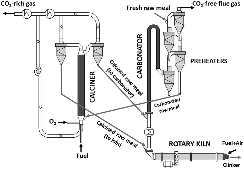 | ||
| Fig. 1 Scheme of a calcium looping arrangement highly integrated in a cement plant. | ||
For the conditions of interest in this work, the existing knowledge on the thermal decomposition of CaCO3 suggests that this can be limited by three controlling stages: heat transfer from the gas phase to the reaction surface, the intrinsic chemical reaction and the mass transfer of CO2 resulting from the calcination reaction to the gas phase.1,40 The contribution of every resistance to the overall reaction is greatly influenced by the operating conditions, the experimental device and the particle size.40 It is generally accepted that the contribution of heat transfer to the calcination kinetics becomes less important as the particle size decreases,1,40–49 which makes both the chemical reaction and CO2 mass transfer from the solid surface to the bulk gas the most important controlling stages for the calcination of cement raw meals. Borgwardt1 observed that the chemical reaction is the controlling step for solids with particle sizes below 90 μm, with the calcination rate being directly related to the surface area of the solid. Hu and Scaroni47 used the equation proposed by Borgwardt1 while also considering resistances to heat and CO2 mass transfer, which become more relevant for larger particles and calcination temperatures higher than 1000 °C. The calcination of CaCO3 particles with initially low porosity has been typically described using a shrinking core model (SCM), in which the reaction rate is proportional to the difference between the equilibrium partial pressure and the CO2 partial pressure.41–44,46,48,50–52 When the calcination is carried out under CO2-rich atmospheres, an induction period is usually observed at low solid conversions, which may be caused by pore enlargement as CaO is formed. Khinast et al.40 proposed a random pore model (RPM) to represent the calcination kinetics under these conditions. The grain model developed by Szekely and Evans53 has also been used to describe the calcination of CaCO3 assuming that the solids are composed of spherical grains of uniform size and each one is calcined following a SCM pattern.49,54–56 García-Labiano et al.48 considered that a porous structure is formed during calcination due to the lower molar volume of calcium oxide. The reaction can then be modelled by a changing grain size pattern. Okunev et al.57 also assumed the shrinkage of the calcined grains and the formation of CaO nuclei is the limiting factor for the overall reaction. Valverde et al.2 studied specifically the calcination rate of fine particles of limestone (about 10 μm) operating with partial pressures of CO2 and temperatures near equilibrium. They observed that the CaCO3 decomposition rate becomes lower as the calcination temperature increases, whenever the PCO2/Peq ratio remains constant. They explained this phenomenon with a two-stage reaction mechanism, in which CaCO3 first decomposes into an intermediate structure with active sites for CO2, and then CO2 is desorbed giving rise to the (exothermic) formation of stable CaO. Recent studies have evaluated the effect of SO2 and steam (both naturally present in the calciner of a CaL system when coal is used as fuel) on the CaCO3 calcination rate. Qin et al.58 found that a sulfation reaction can slightly inhibit CaCO3 decomposition but only when there is a great proportion of CaSO4 causing porous blockage, which hinders the diffusion of CO2 from the calcination zone towards the external surface of the particles. He et al.59 studied the catalytic effect of steam on CaCO3 calcination and proposed a reaction mechanism at the atomic level, in which H2O is first adsorbed on the CaCO3 surface and subsequently forms intermediate compounds (OH*, H*,  , and
, and  ) that significantly reduce the activation energy of the overall calcination reaction.
In this work, we use the previous background to investigate the calcination of different CaCO3-containing materials under the typical conditions of CaL systems highly-integrated in cement plants (i.e. mean particle sizes below 50 μm, solid/gas contact times of a few seconds, temperatures up to 1000 °C and reaction atmospheres from air to gases containing up to 85 vol% CO2). Kinetic parameters have been obtained under quasi-differential conditions in an electrically heated drop tube reactor. Both the experimental results and the kinetic model fitting the observations could contribute to the development of the CaL technology for the decarbonisation of cement plants.
Experimental section and material characterization
A 6.5 m long and 80 mm internal diameter drop tube reactor was designed and built at INCAR-CSIC (see Fig. 2) to carry out the calcination tests. Three heating elements connected to independent controllers with a capacity of 3 × 3.5 kWe are installed along the reactor in order to counteract heat losses and maintain a uniform axial temperature profile. The tube is surrounded by a 0.2 m width layer of glass wool. There are 12 measurement points distributed uniformly along the drop tube, which make it possible to evaluate the temperature (by means of K-type thermocouples) and solid/gas compositions at different reaction lengths. Each gas sampling line is equipped with a particulate filter to protect the analysers from the solids. Two analysers (ABB EL3020 and ABB AO2000) equipped with IR (URAS26) and O2 analyser (MAGNOS206) modules and two CO2Meter® sensors (GC-0016 COZIR) have been used to measure online the composition of the gas. The measuring ranges of these analysers are 0–35 vol% CO2 and 0–100 vol% CO2, respectively. The content of calcium carbonate in the solid samples captured by isokinetic probes has been measured offline with a LECO® CS230 apparatus, which determines the carbon content by IR analysis. The particles of the raw meals are injected at the top of the drop tube (i.e. at 5.5 m high) together with a carrier gas (air) and move down mixed with the main gas stream composed of air and CO2. An in-house design solids feeding apparatus described in a previous study39 has been used for these tests.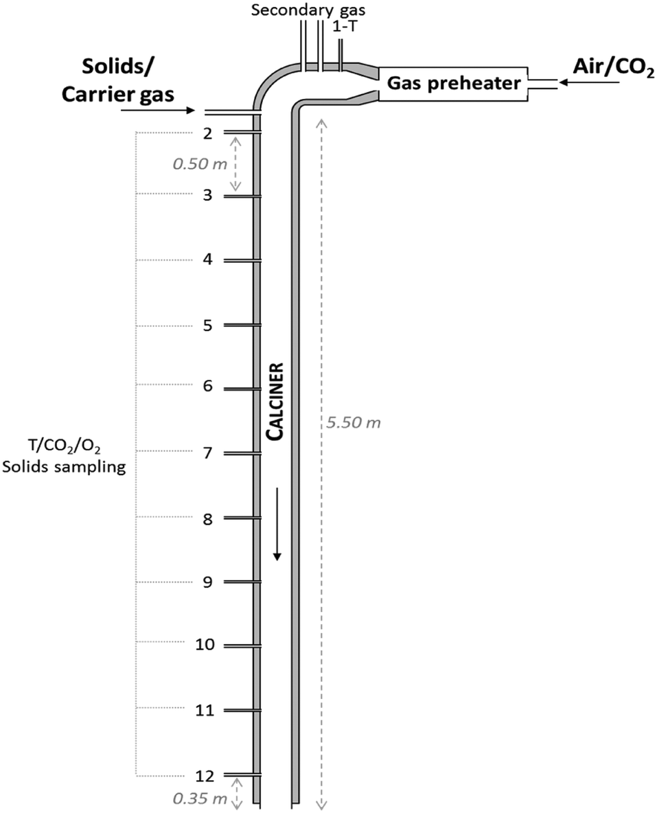 | ||
| Fig. 2 Scheme of the drop tube reactor used in this work for the determination of calcination kinetics of cement raw meals. | ||
A batch of around 150 g of raw meals has been fed into the reactor during each calcination experiment. Flows of about 0.35 Nm3 h−1 of carrier gas (coming from a compressor at 5 bar) and between 0.2 and 1 kg h−1 of solids have been injected during the calcination tests. Both solids and carrier gas have been preheated up to 500 °C before they entered the reactor. Different air/CO2 mixtures have been tested (up to 85 vol% CO2 in air), which have been pre-heated up to 1100 °C using a Kanthal® electric gas preheater with a capacity of 3.5 kWe. Air flow rates ranging from 0.5 to 8.3 Nm3 h−1 have been supplied using a blower, while CO2 has come from commercial flasks. Air and CO2 flow rates have been regulated using Bronkhorst mass flow controllers. All the electric signals from the thermocouples, gas analysers and mass flow controllers have been collected using a data logger.
The tests have been carried out with very low amounts of solids suspended in large flows of air/CO2 (solid-to-gas ratios below 0.06 kg/kg) that circulate at velocities of up to 2.2 m s−1 and gas/solid contact times below 1.5 s. This operation has allowed the determination of calcination kinetics under differential conditions with respect to the gas (i.e. with modest changes in CO2 concentration in the reaction environment along the drop tube as will be seen below). The ranges of operating conditions tested in the drop tube reactor are summarized in Table 1.
| Calcination temperature (°C) | 790–1000 |
| Gas velocity (m s−1) | 1.1–2.2 |
| Inlet gas flow (Nm3 h−1) | 4.7–9.3 |
| Inlet CO2 volume fraction | 0–0.85 |
| Solids flow rate (kg h−1) | 0.2–1.0 |
| Average particle size (μm) | 7–51 |
Several limestones and cement raw meals have been tested (see Table 2). Compostilla and Calcare are natural limestones, Marine and Geseke are natural marls, and Vernasca, Belitic and Rumelange are mixtures of different limestones and natural marls. Three different fractions of Compostilla (i.e. CP1, CP2 and CP3) with different particle size distributions were obtained after milling and sieving operations in order to study the effect of the particle size and surface area on the calcination kinetics. The chemical compositions of these materials have been determined by X-ray fluorescence with a Bruker spectrometer SRS 3000. As can be seen in Table 2, both Compostilla and Calcare are limestones of high purity with very similar CaO content (around 52 wt%). The main impurities of Compostilla and Calcare are SiO2 (<3 wt%) and MgO (<2 wt%). The rest of the materials tested in this work are basically composed of CaO (between 37 and 42 wt%), SiO2 (14 and 21 wt%) and Al2O3 (between 3 and 5 wt%), whose composition corresponds to typical raw meals used for clinker manufacture.60
| Oxide (wt%) | Compostilla | Calcare | Vernasca | Marine | Geseke | Rumelange | Belitic |
|---|---|---|---|---|---|---|---|
| a Loss on ignition, 1CP1, 2CP2, 3CP3. | |||||||
| CaO | 51.7 | 53.2 | 41.5 | 37.2 | 43.2 | 43.8 | 39.7 |
| SiO2 | 2.7 | 0.4 | 15.2 | 21.4 | 15.8 | 14.3 | 16.1 |
| Al2O3 | 1.0 | 0.2 | 3.6 | 5.1 | 2.9 | 2.7 | 3.2 |
| Fe2O3 | 0.5 | 0.1 | 2.1 | 1.8 | 0.9 | 2.3 | 1.3 |
| P2O5 | — | — | 0.1 | 0.1 | 0.1 | — | — |
| K2O | 0.2 | — | 0.6 | 0.1 | 0.3 | 0.2 | 0.5 |
| Na2O | — | — | — | 0.2 | 0.1 | — | — |
| TiO2 | 0.1 | — | 0.1 | 0.2 | 0.1 | 0.1 | 0.2 |
| MgO | 1.0 | 1.9 | 1.2 | 1.2 | 0.5 | 0.7 | 1.8 |
| SO3 | 0.2 | 0.1 | 0.1 | 0.2 | 0.4 | 0.4 | 3.8 |
| MnO | — | — | 0.1 | 0.1 | 0.1 | 0.2 | 0.1 |
| SrO | — | — | 0.1 | 0.1 | 0.1 | 0.1 | 0.1 |
| ZrO2 | — | — | — | — | 0.1 | — | — |
| LOIa | 42.6 | 44.0 | 35.3 | 32.3 | 35.4 | 34.5 | 33.2 |
| BET area, m2 g−1 | 3.11/4.02/4.03 | 1.4 | 13.5 | 13.7 | 4.3 | 6.1 | 10.8 |
| dp50, μm | 511/262/113 | 8 | 10 | 10 | 7 | 11 | 10 |
BET surface areas were determined from nitrogen adsorption tests at −195 °C using a Micromeritics ASAP 2460 instrument. The limestones present similar low values of BET areas in the range from 1.4 to 4 m2 g−1. Geseke and Rumelange also show BET areas of 4.3 and 6.1 m2 g−1, respectively, whereas Vernasca, Marine and Belitic exhibit noticeable higher BET areas (11–13.7 m2 g−1), which correspond to typical values reported in the literature for these types of materials.38 The particle size distributions of the fresh materials were obtained by laser diffraction using an LS13320 Beckman Coulter apparatus. Fig. 3 shows the particle size distribution (PSD) and the median diameter (dp50) of four of the CaCO3 materials tested in this work.
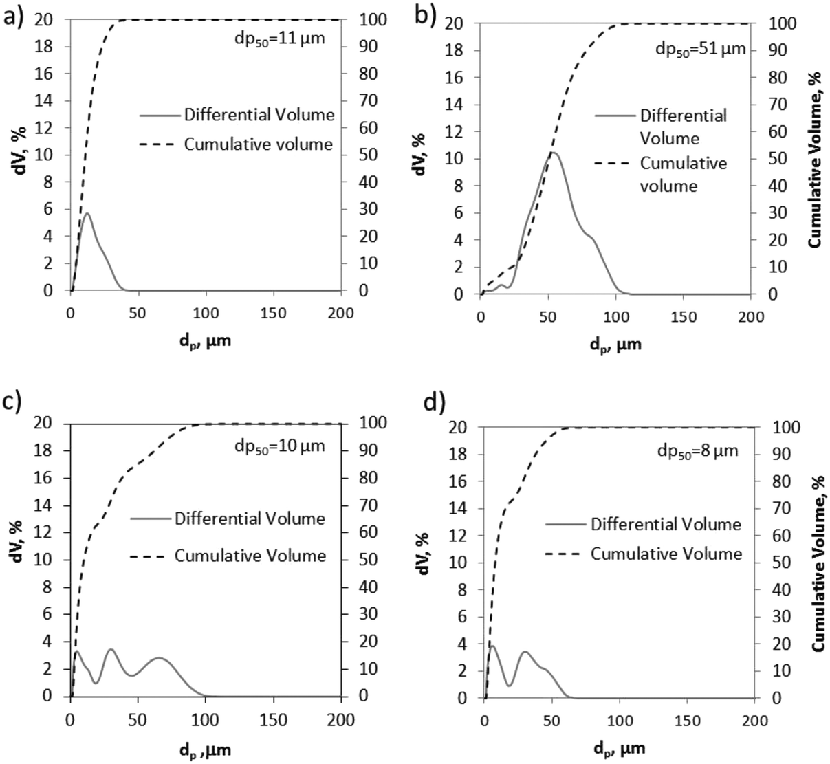 | ||
| Fig. 3 Particle size distribution of different CaCO3 materials: a) CP3, b) CP1, c) Vernasca, and d) Calcare. | ||
As can be seen, both samples of CP3 and CP1 (Fig. 3a and b, respectively) exhibit narrow PSDs with predominant volume percentages at particle diameters of about 11 and 51 μm. In contrast, the samples of Vernasca and Calcare (tested as they were supplied from the cement plants) show more homogeneous PSDs. The median diameters (dp50) are 10 and 8 μm, with 85% and 95% volume of the particles lower than 50 μm, respectively. Finally, values between 7 and 11 μm (dp50) are measured for the rest of the materials listed in Table 1.
The PSD curves of these solids are similar to those obtained for Vernasca and Calcare and they are not shown for the sake of simplicity.
The main crystalline phases present in the fresh and calcined samples of the CaCO3 materials were identified by X-ray diffraction (XRD) using a Siemens D500 powder diffractometer equipped with a copper Kα monochromatic detector. Each analysis was carried out in the 2θ range of up to 90° with a step size of 0.02° and a scan time per step of 1 s. Fig. 4 shows an example of X-ray spectra of fresh and calcined samples of Vernasca raw meal (at 840 and 950 °C in air). As expected in the sample of fresh raw meal, the principal peak intensities correspond to calcium carbonate and silica. In the calcined samples, apart from the peaks of CaO, less SiO2 is measured and small amounts of calcium silicates, mainly belite (Ca2SiO4), are detected. These results confirm that the calcination of cement raw meals at temperatures above 840 °C allows appreciable amounts of calcium silicates to be irreversibly formed even for very short calcination times, which partially undermines the CO2 capture capacity of these materials.61
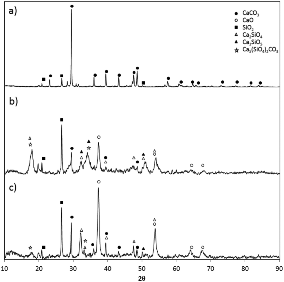 | ||
| Fig. 4 X-Ray diffractograms of fresh and calcined Vernasca raw meal: a) fresh sample, b) calcined sample (at 840 °C in air for 0.5 s), and c) calcined sample (at 950 °C in air for 0.3 s). | ||
Results and discussion
In order to extract kinetic information from the solid conversion measurements in the drop tube apparatus, it is important to determine first the solid residence times under calcination conditions. The fine particles used in all experiments, the good level of dispersion in the carrier gas of the feeding system and the fast extraction and cooling of the solids in the isokinetic probes support the assumption that the solid residence time is the same as the gas residence time between two sections of the drop tube. To estimate possible deviations from the plug flow pattern of the gas, preliminary tests were performed to determine the residence time distribution (RTD) inside the drop tube. Abrupt variations between 12 and 0 vol% CO2 in the inlet gas were used as tracers to obtain the experimental RTD. The degree of axial dispersion was estimated by following the methodology explained in detail in a previous study.39Fig. 5a shows the experimental and theoretical F(t) lines resulting from the step tests.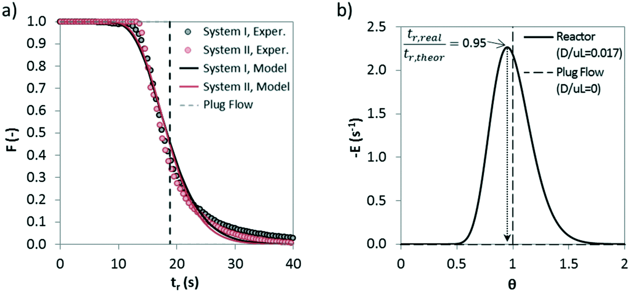 | ||
| Fig. 5 a) Example of an RTD curve during step tracer experiments to estimate gas dispersion in the drop tube apparatus (T = 750 °C, inlet gas flow of 2.7 Nm3 h−1). System I includes the drop tube, analyzer and connecting line and system II refers to the pipeline downstream of the reactor and the analyzer; b) deviation from ideal plug flow for a pulse input. | ||
It has been calculated the dispersion of the complete system (represented in Fig. 5 as system I), which includes the drop tube, analyzer and the connecting line in between, and also the dispersion only caused by caused the analyzer and the pipeline that connects the reactor and the analyzer (represented in Fig. 5 as system I). A dispersion number (D/μL) of 0.017 has been obtained for the reactor, which indicates a modest dispersion, and a dispersion coefficient (D) value of 0.05 m2 s−1 has been calculated. Very similar values of 0.012 and 0.04 m2 s−1 can be obtained for D/μL and D, respectively, using a well-known correlation reported by Levenspiel62 for the estimation of axial dispersion in pipelines. Fig. 5b shows a representative E(t) curve (dF/dt) versus the normalized residence time (θ) for a dispersion number of 0.017. As can be seen, the moderate dispersion existing in the drop tube for the conditions of this work makes the real residence time of the gas inside the reactor slightly lower than the theoretical one calculated assuming an ideal plug flow pattern (i.e. tr,real/tr,theor = 0.95). This minor deviation has been considered in the calculation of the kinetic parameters explained below.
For the actual calcination experiments, different reactor lengths between 0.5 and 2.5 m were considered depending on the feeding and gas/solid extraction points in the test to ensure controlled and stable temperatures in the reaction zones and to facilitate the access to intermediate conversion information. The extent of the calcination conversion was obtained from measuring the variation of both the CO2 concentration in the gas phase and the carbon content of the solid samples along the reaction zone.
In a typical experiment, as shown in Fig. 6, the evolution with time of the concentration of CO2 at the inlet and outlet of the drop tube is recorded. There is a starting period, 1, in which only the preheated mixture of air and CO2 is fed into the reactor. The inlet mass flow rates of air and CO2 are then verified by measuring the gas composition (%CO2,in) in the absence of a chemical reaction. In a subsequent stage, 2, the flow of air that acts as a solids carrier is injected into the drop tube, giving as a result a dilution of the CO2 content measured in the analyzers (from 16 vol% to about 15.5 vol% CO2 for the particular experiment presented in Fig. 6). Once the temperature and CO2 concentration remain stable, the solids are injected to initiate the calcination period, 3. In this particular test, the variation of CO2 concentration in the gas phase has been measured at lengths of 1 and 2.5 m from the solids injection point (%CO2out). As can be seen, the CO2 content rapidly increases due to the decomposition of CaCO3 present in the inlet solids, and after a short period of time, reasonably steady values are measured at L = 1 m (≈15.8 vol% CO2) and L = 2.5 m (≈16.1 vol% CO2), according to the extent of the calcination conversion. After several minutes of operation under stable conditions, the addition of solids is shut off and as a consequence, the concentration of CO2 decreases until the initial value (15.5 vol% CO2) is achieved (period 4). Finally, the flow of carrier air is stopped (period 5) and the CO2 measured in the gas returns to the initial value (i.e. 16 vol% CO2 in this case), which confirms that any alteration of the flows or possible infiltration of air in the lines has been avoided.
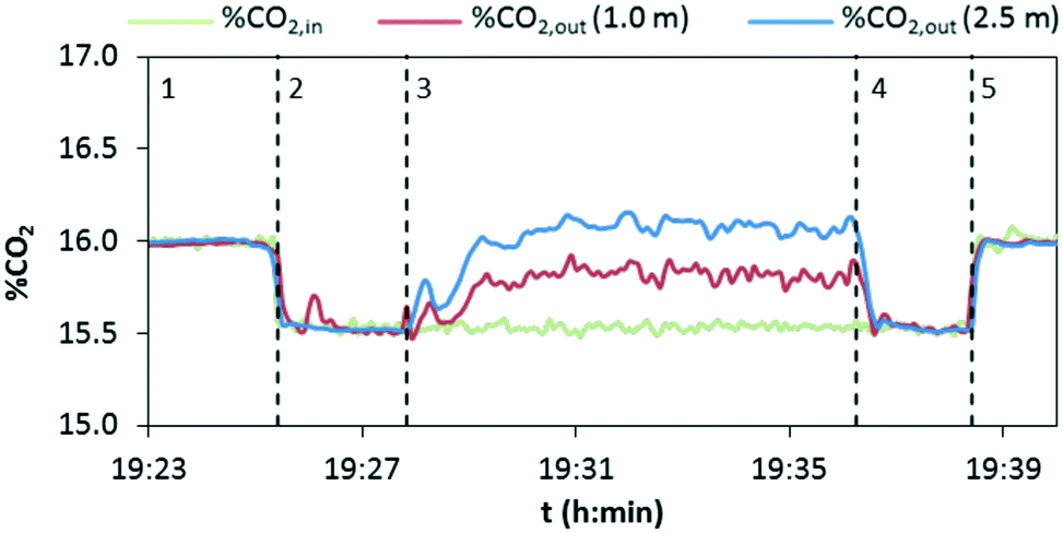 | ||
| Fig. 6 Evolution of the CO2 content in the gas flowing through the drop tube in three locations during a calcination test (material: Compostilla CP1, calcination temperature 860 °C, gas velocity = 2 m s−1, solids flow rate = 0.65 kg h−1). | ||
From the experimental information obtained in each calcination test, the following CO2 mass balance based on the gas phase has been solved to calculate the conversion of CaCO3 to CaO (Xcalc):
| (FCO2out − FCO2in) = FCaCO3inXcalc | (1) |
It is also possible to calculate the extent of the calcination conversion by means of eqn (2) from the solids samples taken during each test, which are subjected to offline chemical analyses (explained above) to measure the variations in the carbon content along the reactor:
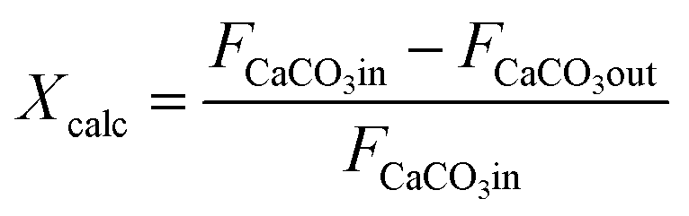 | (2) |
Thus, FCaCO3out is the molar flow at the exit determined from the chemical analysis of the solid particles collected. This methodology allows the internal reliability of the experimental results to be validated since the increase in the CO2 measured in the gas phase must correspond to the reduction of the carbon content measured using LECO on the solid samples.
As explained in the Introduction section, the model proposed by Borgwardt1 has been used by several authors to describe the calcination of fine particles (<90 μm) of CaCO3 in air at temperatures between 700 and 1000 °C, in which the chemical reaction is the controlling step (eqn (3)).
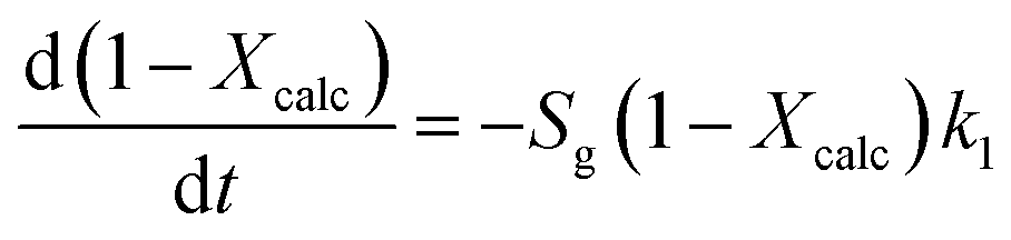 | (3) |
According to eqn (3), the calcination rate depends directly on the specific BET surface area (Sg) of the material. The calcination conversion (Xcalc) can then be calculated from the integrated equation (eqn (4)), in which k1 is the reaction rate constant that follows an Arrhenius dependence on temperature.
| Xcalc = 1 − e−k1Sgtr | (4) |
Fig. 7 presents the evolution of the calcination conversion of four materials taken as examples (i.e. CP1, CP2, CP3 and Calcare), obtained at temperatures between 790 and 950 °C in air atmosphere. As expected, higher temperatures and higher surface areas promote the decomposition of CaCO3. For CP2 (Fig. 7b), which exhibits a BET area of 4 m2 g−1 (see Table 1), almost total calcination is achieved after 1 s of operation at 840 °C. However, less than 80% of the CaCO3 in this material is converted at 790 °C after 1.3 s. In the case of Calcare (Fig. 7d), with a significantly lower BET area (1.4 m2 g−1), only 0.70 calcination conversion is achieved after 1 s at 840 °C. As can be seen, the model developed by Borgwardt predicts reasonably well the extent of the calcination conversion for the materials shown in Fig. 7 when using the activation energy reported by Borgwardt (i.e. 195 kJ mol−1) and when adjusting the pre-exponential factors for each material (represented as a1 in Table 2).
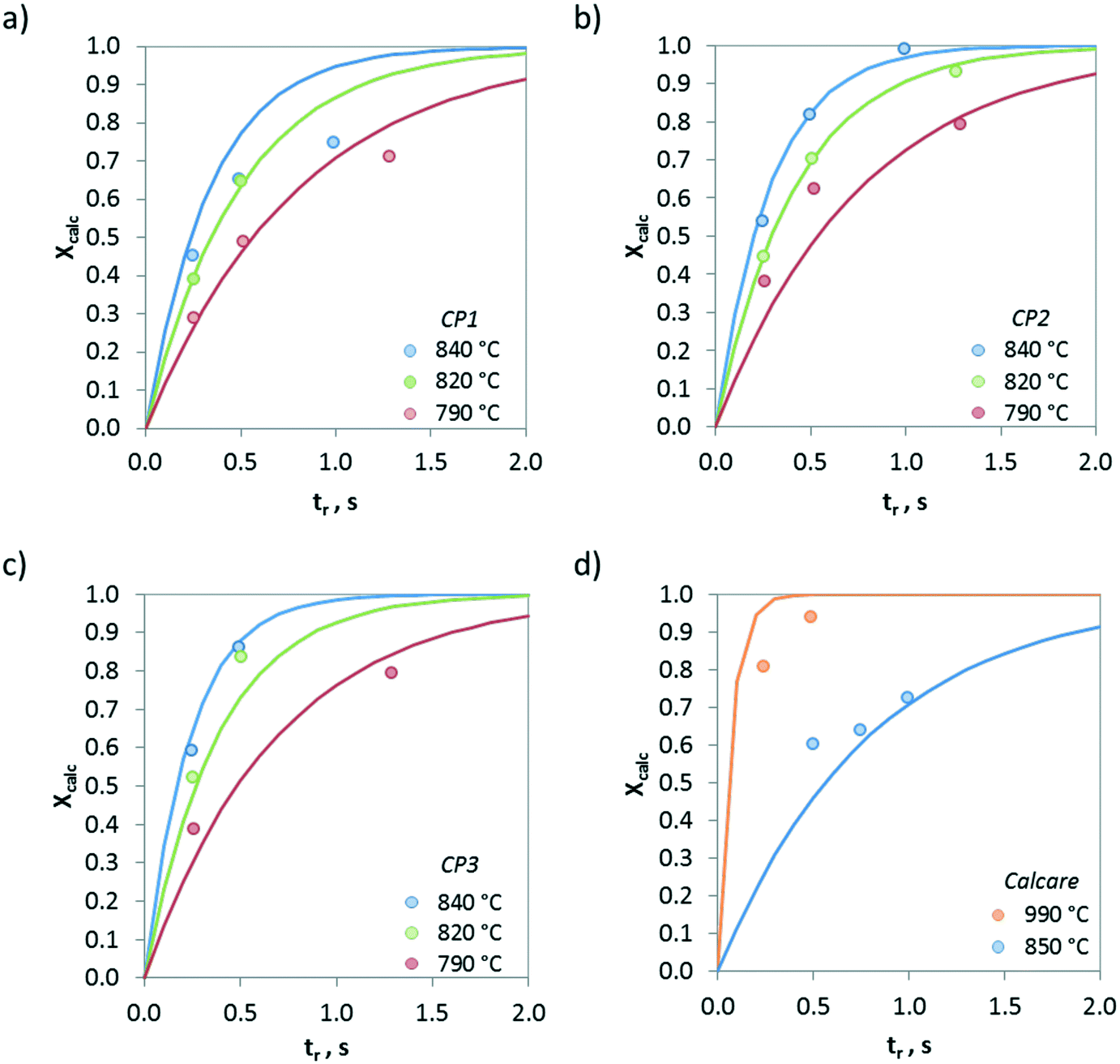 | ||
| Fig. 7 Evolution of calcination conversion obtained in the drop tube under air atmosphere. a) CP1, b) CP2, c) CP3, and d) Calcare. Solid lines correspond to predictions given by Borgwardt's model with the parameters listed in Table 2. | ||
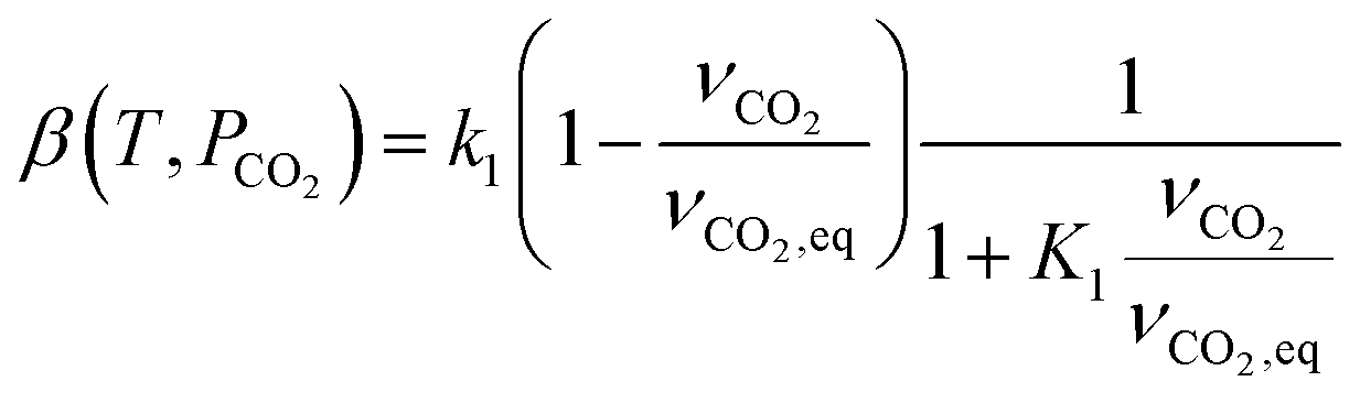
However, the model proposed by Borgwardt does not take into account the effect of the CO2 content in the gas phase on the calcination rate. For this reason, a modification has been implemented in this model to solve this limitation. The kinetic rate constant has been redefined according to eqn (5).
| Xcalc = 1 − e−β(T,PCO2)Sgtr | (5) |
 | (6) |
| r1 = k1(1 − ϕ) − k2ϕ | (7) |
 | (8) |
| r2 = kdϕ − ka(1 − ϕ)PCO2 | (9) |
 | (10) |
 | (11) |
 | (12) |
The same values reported by Borgwardt1 for the activation energy (i.e. 195 kJ mol−1) and by Valverde et al.2 for Δ1H° (i.e. 150 kJ mol−1) have been assumed in this work. The kinetic parameters a1 and A1 have been calculated for each CaCO3-based material by fitting the experimental data (see Table 3).
| Material | a 1 (mol m−2 s−1) | A 1 (−) |
|---|---|---|
| Compostilla | 11.7 × 10⁶ | 153 × 106 |
| Calcare | 11.9 × 10⁶ | 219 × 106 |
| Vernasca | 2.9 × 10⁶ | 137 × 106 |
| Marine | 3.0 × 10⁶ | 43 × 106 |
| Geseke | 5.8 × 10⁶ | 66 × 106 |
| Rumelange | 4.9 × 10⁶ | 239 × 106 |
| Belitic | 1.6 × 10⁶ | 28 × 106 |
Fig. 8 shows the effect of the temperature on the calcination conversion of CaCO3 materials of different origins and compositions. As expected, the calcination temperature has a strong effect on Xcalc. Thus, temperatures above 900 °C promote the calcination reaction and Xcalc values higher than 0.5 are achieved for residence times below 0.5 s in the drop tube, regardless of whether the solid is a limestone or a mixture of CaCO3 and SiO2. However, the calcination conversions at 820 °C for longer reaction times (tr > 1 s) are lower than 0.15.
 | ||
| Fig. 8 Effect of temperature on the calcination conversion for CaCO3 materials of different origins and compositions. a) Belitic (mixture of limestone and marl), b) CP1 (limestone), c) Vernasca (mixture of limestone and marl), and d) Rumelange (mixture of limestone and marl). Solid lines correspond to model predictions. | ||
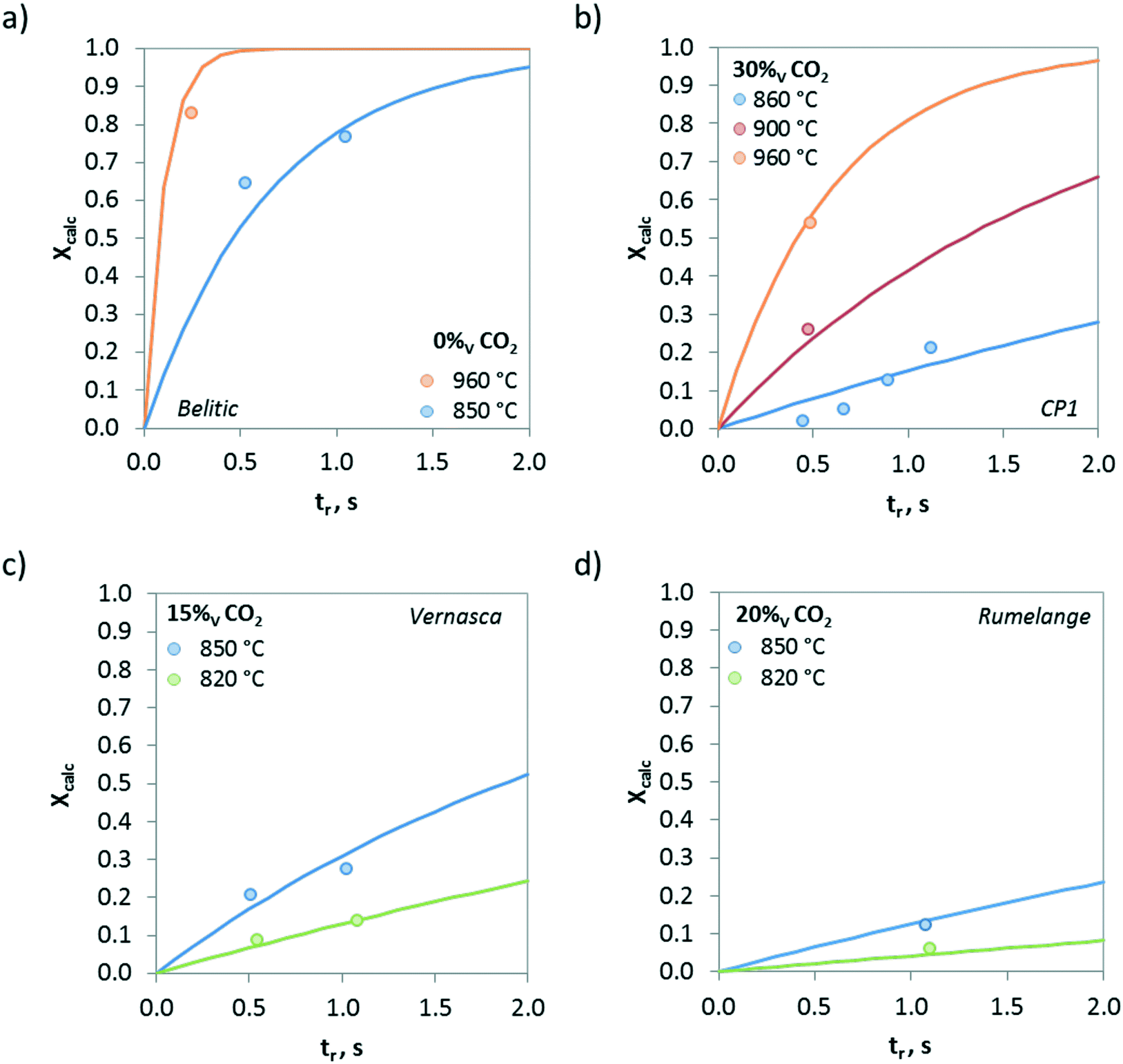
The evolution of the calcination conversion under different CO2 concentrations (from 0 to 85 vol%) is presented in Fig. 9. As can be seen, increasing contents of CO2 in the atmosphere hinder the calcination of CaCO3 due to equilibrium restrictions, and consequently, lower Xcalc values are obtained for the same operating temperature. However, it must be highlighted that relevant calcination conversions can be achieved under high CO2 concentrations even at very short reaction times. As an example, samples of Belitic (mixture of limestone and marl) achieved a solid conversion of 0.2 in approximately 1 s in the drop tube when the calcination was carried out at 850 °C under 40 vol% CO2 (Fig. 9b). In the case of Marine (marl), an Xcalc of 0.2 was achieved in less than 0.5 s under 80 vol% CO2 at 940 °C (Fig. 9c).
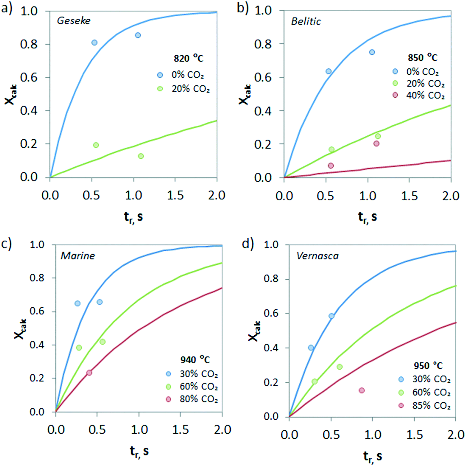 | ||
| Fig. 9 Effect of the concentration of CO2 in the gas phase on the calcination conversion for CaCO3 materials of different origins and compositions. a) Geseke (marl), b) Belitic (mixture of limestone and marl), c) Marine (marl), and d) Vernasca (mixture of limestone and marl). Solid lines correspond to model predictions. | ||
Finally, the comparison between the calcination conversions obtained experimentally in the drop tube and the calculated values using the proposed model with the kinetic parameters listed in Table 3 is presented in Fig. 10. As can be seen, despite the modest regression coefficients (R2 values of 0.91 and 0.86 have been obtained for limestone and CaCO3–SiO2 materials, respectively) the model predicts reasonably well the extent of the solids conversion for each material, in particular when considering the inherent limitations of the experimental set up and the short gas–solid contact times used in this study.
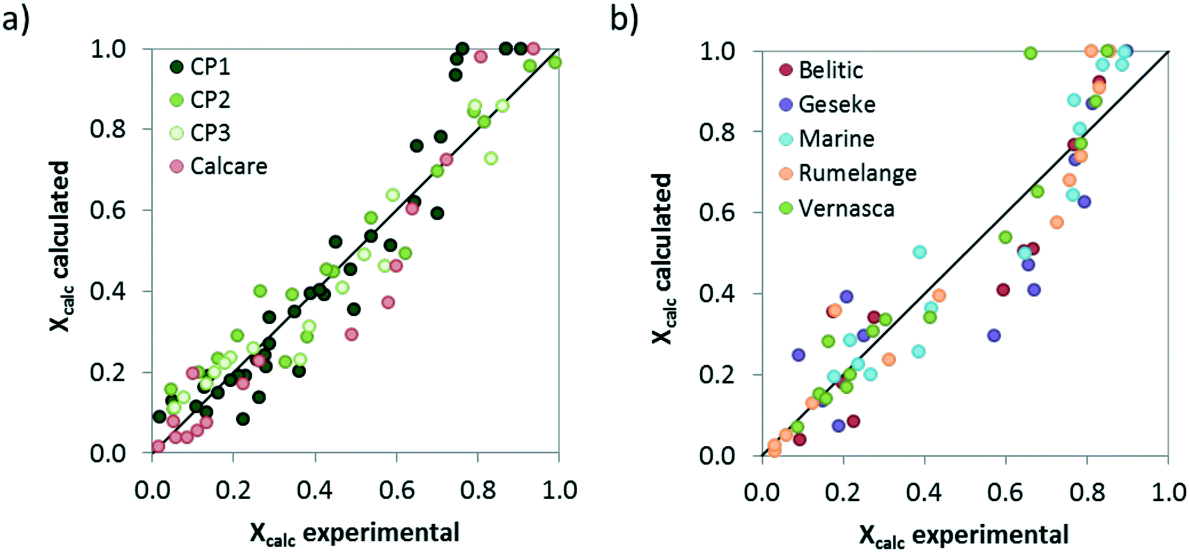 | ||
| Fig. 10 Comparison between the calcination conversions obtained in the drop tube and the values given by the proposed model assuming the kinetic parameters listed in Table 3. a) Limestones, b) marls and mixed Ca–Si materials. | ||
These results confirm that high solid conversions can be obtained with CaCO3 materials of different characteristics when the calcination is carried out under typical conditions of calcium looping systems highly integrated in cement plants.
Conclusions
The calcination of several high purity limestones, natural marls and combined CaCO3–SiO2 raw meals has been investigated in an electrically heated drop tube under relevant conditions of a calcium looping process integrated in a cement plant. The calcination tests have been carried out with fine solids with average particle sizes below 50 μm, at temperatures between 790 and 1000 °C and CO2 contents in the atmosphere up to 85 vol%. As expected, higher temperatures and lower concentrations of CO2 in the gas favour the calcination of CaCO3 regardless of whether the solid is a limestone or a combined Ca–Si material. Calcination conversions higher than 0.5 have been achieved at temperatures above 900 °C for residence times of the solids in the drop tube of about 1 s. XRD analyses show that a certain amount of calcium silicates is also formed during the calcination at temperatures above 840 °C. The calcination of all the materials tested in this work can be reasonably well described by means of a standard calcination model, in which the reaction rate depends directly on the specific BET surface area of the solid and the activation energy takes a value of 195 kJ mol−1. Both experimental and kinetic studies should provide valuable information for the progress of calcium looping integrated in cement plants.Conflicts of interest
There are no conflicts to declare.Acknowledgements
This investigation has been funded by the European Union's Horizon 2020 Research and Innovation Programme under the H2020 grant agreement no. 764816 (CLEANKER Project).Notes and references
- R. H. Borgwardt, AIChE J., 1985, 31, 103–111 CrossRef CAS.
- J. M. Valverde, P. E. Sanchez-Jimenez and L. A. Perez-Maqueda, J. Phys. Chem. C, 2015, 119, 1623–1641 CrossRef CAS.
- J. C. Abanades, B. Arias, A. Lyngfelt, T. Mattisson, D. E. Wiley, H. Li, M. T. Ho, E. Mangano and S. Brandani, Int. J. Greenhouse Gas Control, 2015, 40, 126–166 CrossRef CAS.
- D. P. Hanak, E. J. Anthony and V. Manovic, Energy Environ. Sci., 2015, 8, 2199–2249 RSC.
- I. Martínez, G. Grasa, J. Parkkinen, T. Tynjälä, T. Hyppänen, R. Murillo and M. C. Romano, Int. J. Greenhouse Gas Control, 2016, 50, 271–304 CrossRef.
- M. E. Diego, B. Arias and J. C. Abanades, J. Cleaner Prod., 2016, 117, 110–121 CrossRef CAS.
- M.-H. Chang, C.-M. Huang, W.-H. Liu, W.-C. Chen, J.-Y. Cheng, W. Chen, T.-W. Wen, S. Ouyang, C.-H. Shen and H.-W. Hsu, Chem. Eng. Technol., 2013, 36, 1525–1532 CrossRef CAS.
- J. Hilz, M. Haaf, M. Helbig, N. Lindqvist, J. Ströhle and B. Epple, Int. J. Greenhouse Gas Control, 2019, 88, 332–341 CrossRef CAS.
- G. S. Grasa and J. C. Abanades, Chem. Eng. Sci., 2007, 62, 619–626 CrossRef CAS.
- M. Reitz, M. Junk, J. Ströhle and B. Epple, Int. J. Greenhouse Gas Control, 2016, 54, 272–281 CrossRef CAS.
- D. Hoeftberger and J. Karl, J. Energy Resour. Technol., 2016, 138, 042211 CrossRef.
- T. P. Hills, M. Sceats, D. Rennie and P. Fennell, Energy Procedia, 2017, 114, 6166–6170 CrossRef CAS.
- J. Wolf and J. Yan, Int. J. Eng. Res., 2005, 29, 739–753 CAS.
- M. E. Diego, B. Arias, A. Méndez, M. Lorenzo, L. Díaz, A. Sánchez-Biezma and J. C. Abanades, Int. J. Greenhouse Gas Control, 2016, 50, 14–22 CrossRef CAS.
- J. R. Fernández and J. C. Abanades, J. Cleaner Prod., 2016, 112, 1211–1217 CrossRef.
- R. V. Kumar, R. K. Lyon and J. A. Cole, in Advances in Hydrogen Energy, ed. C. E. Grégoire Padró and F. Lau, Springer, US, Boston, MA, 2002, pp. 31–45, DOI:10.1007/0-306-46922-7_3.
- J. C. Abanades, R. Murillo, J. R. Fernandez, G. Grasa and I. Martínez, Environ. Sci. Technol., 2010, 44, 6901–6904 CrossRef CAS PubMed.
- B. Arias, M. E. Diego, A. Méndez, M. Alonso and J. C. Abanades, Fuel, 2018, 222, 711–717 CrossRef CAS.
- ECRA, CCS—Carbon Capture and Storage, Available online: https://ecra-online.org/research/ccs/ Search PubMed.
- S. O. Gardarsdottir, E. De Lena, M. Romano, S. Roussanaly, M. Voldsund, J.-F. Pérez-Calvo, D. Berstad, C. Fu, R. Anantharaman, D. Sutter, M. Gazzani, M. Mazzotti and G. Cinti, Energies, 2019, 12, 542 CrossRef CAS.
- N. Rodríguez, R. Murillo and J. C. Abanades, Environ. Sci. Technol., 2012, 46, 2460–2466 CrossRef PubMed.
- L. M. Romeo, D. Catalina, P. Lisbona, Y. Lara and A. Martínez, Greenhouse Gases: Sci. Technol., 2011, 1, 72–82 CrossRef CAS.
- A. Telesca, D. Calabrese, M. Marroccoli, M. Tomasulo, G. L. Valenti, G. Duelli and F. Montagnaro, Fuel, 2014, 118, 202–205 CrossRef CAS.
- K. Vatopoulos and E. Tzimas, J. Cleaner Prod., 2012, 32, 251–261 CrossRef CAS.
- IEA and CSI, Technology Roadmap: Low-Carbon Transition in the Cement Industry, International Energy Agency, Cement Sustainability Initiative, 2018 Search PubMed.
- A. Rolfe, Y. Huang, M. Haaf, A. Pita, S. Rezvani, A. Dave and N. J. Hewitt, Int. J. Greenhouse Gas Control, 2018, 75, 85–97 CrossRef CAS.
- D. C. Ozcan, H. Ahn and S. Brandani, Int. J. Greenhouse Gas Control, 2013, 19, 530–540 CrossRef CAS.
- K. Atsonios, P. Grammelis, S. K. Antiohos, N. Nikolopoulos and E. Kakaras, Fuel, 2015, 153, 210–223 CrossRef CAS.
- M. C. Romano, M. Spinelli, S. Campanari, S. Consonni, M. Marchi, N. Pimpinelli and G. Cinti, Energy Procedia, 2014, 61, 500–503 CrossRef CAS.
- M. Spinelli, I. Martínez and M. C. Romano, Chem. Eng. Sci., 2018, 191, 100–114 CrossRef CAS.
- E. De Lena, M. Spinelli, I. Martínez, M. Gatti, R. Scaccabarozzi, G. Cinti and M. C. Romano, Int. J. Greenhouse Gas Control, 2017, 67, 71–92 CrossRef CAS.
- M. Spinelli, I. Martínez, E. De Lena, G. Cinti, M. Hornberger, R. Spörl, J. C. Abanades, S. Becker, R. Mathai, K. Fleiger, V. Hoenig, M. Gatti, R. Scaccabarozzi, S. Campanari, S. Consonni and M. C. Romano, Energy Procedia, 2017, 114, 6206–6214 CrossRef CAS.
- E. De Lena, M. Spinelli, M. Gatti, R. Scaccabarozzi, S. Campanari, S. Consonni, G. Cinti and M. C. Romano, Int. J. Greenhouse Gas Control, 2019, 82, 244–260 CrossRef CAS.
- B. Arias, M. Alonso and C. Abanades, Ind. Eng. Chem. Res., 2017, 56, 2634–2640 CrossRef CAS.
- M. Hornberger, R. Spörl and G. Scheffknecht, Energy Procedia, 2017, 114, 6171–6174 CrossRef CAS.
- S. K. Pathi, W. Lin, J. B. Illerup, K. Dam-Johansen and K. Hjuler, Energy Fuels, 2013, 27, 5397–5406 CrossRef CAS.
- M. Alonso, Y. Álvarez Criado, J. R. Fernández and C. Abanades, Energy Fuels, 2017, 31, 13955–13962 CrossRef CAS.
- J. Plou, I. Martínez, G. S. Grasa and R. Murillo, React. Chem. Eng., 2019, 4, 899–908 RSC.
- S. Turrado, B. Arias, J. R. Fernández and J. C. Abanades, Ind. Eng. Chem. Res., 2018, 57, 13372–13380 CrossRef CAS.
- J. Khinast, G. F. Krammer, C. Brunner and G. Staudinger, Chem. Eng. Sci., 1996, 51, 623–634 CrossRef CAS.
- C. N. Satterfield and F. Feakes, AIChE J., 1959, 5, 115–122 CrossRef CAS.
- T. R. Ingraham and P. Marier, Can. J. Chem. Eng., 1963, 41, 170–173 CrossRef CAS.
- A. W. D. Hills, Chem. Eng. Sci., 1968, 23, 297–320 CrossRef CAS.
- F. R. Campbell, A. W. D. Hills and A. Paulin, Chem. Eng. Sci., 1970, 25, 929–942 CrossRef CAS.
- D. Beruto and A. W. Searcy, J. Chem. Soc., Faraday Trans. 1, 1974, 70, 2145–2153 RSC.
- J. S. Dennis and A. N. Hayhurst, Chem. Eng. Sci., 1987, 42, 2361–2372 CrossRef CAS.
- N. Hu and A. W. Scaroni, Fuel, 1996, 75, 177–186 CrossRef CAS.
- F. García-Labiano, A. Abad, L. F. de Diego, P. Gayán and J. Adánez, Chem. Eng. Sci., 2002, 57, 2381–2393 CrossRef.
- I. Martínez, G. Grasa, R. Murillo, B. Arias and J. C. Abanades, Energy Fuels, 2012, 26, 1432–1440 CrossRef.
- C. R. Milne, G. D. Silcox, D. W. Pershing and D. A. Kirchgessner, Ind. Eng. Chem. Res., 1990, 29, 139–149 CrossRef CAS.
- G. D. Silcox, J. C. Kramlich and D. W. Pershing, Ind. Eng. Chem. Res., 1989, 28, 155–160 CrossRef CAS.
- J. Ylätalo, J. Parkkinen, J. Ritvanen, T. Tynjälä and T. Hyppänen, Fuel, 2013, 113, 770–779 CrossRef.
- J. Szekely and J. W. Evans, Chem. Eng. Sci., 1970, 25, 1091–1107 CrossRef CAS.
- F. Fang, Z.-S. Li and N.-S. Cai, Energy Fuels, 2009, 23, 207–216 CrossRef CAS.
- M. S. Murthy, B. R. Harish, K. S. Rajanandam and K. Y. Ajoy Pavan Kumar, Chem. Eng. Sci., 1994, 49, 2198–2204 CrossRef CAS.
- T. Rajeswara Rao, D. J. Gunn and J. H. Bowen, Chem. Eng. Res. Des., 1989, 67, 38–47 Search PubMed.
- A. G. Okunev, S. S. Nesterenko and A. I. Lysikov, Energy Fuels, 2008, 22, 1911–1916 CrossRef CAS.
- C. Qin, D. He, Z. Zhang, L. Tan and J. Ran, Chem. Eng. J., 2018, 334, 2238–2249 CrossRef CAS.
- D. He, Z. Ou, C. Qin, T. Deng, J. Yin and G. Pu, Chem. Eng. J., 2020, 379, 122348 CrossRef CAS.
- H. F. Taylor, Cement chemistry, Thomas Telford, 1997 Search PubMed.
- M. Alonso, J. R. Fernández and J. C. Abanades, Ind. Eng. Chem. Res., 2019, 58, 5445–5454 CrossRef CAS.
- O. Levenspiel, J. Ind. Eng. Chem., 1958, 50, 343–346 CrossRef CAS.
| This journal is © The Royal Society of Chemistry 2019 |