 Open Access Article
Model-based scale-up and reactor design for solvent-free synthesis of an ionic liquid in a millistructured flow reactor†
Sebastian
Schwolow
 a,
Benedikt
Mutsch
a,
Norbert
Kockmann
b and
Thorsten
Röder
*a
a,
Benedikt
Mutsch
a,
Norbert
Kockmann
b and
Thorsten
Röder
*a
aMannheim University of Applied Sciences, Institute of Chemical Process Engineering, Paul-Wittsack-Straße 10, 68163 Mannheim, Germany. E-mail: t.roeder@hs-mannheim.de; Tel: +49 621 292 6800
bTU Dortmund University, Biochemical and Chemical Engineering, Equipment Design, Emil-Figge-Straße 68, 44227 Dortmund, Germany
First published on 28th January 2019
Abstract
We investigated solvent-free synthesis of the ionic liquid 1-butyl-3-methylimidazolium bromide in a microreactor setup. Time–conversion curves were used to derive a model for the liquid–liquid two-phase system taking both heat transfer and mass transfer into account. Simulations conducted with parameter variations were used to evaluate the general influence of mass and heat transfer coefficients on the conversion and temperature profiles in a flow reactor. A scale-up of the microreactor experiments to production in a millistructured plate reactor can be limited by insufficient heat removal, which results in parametric sensitivity. Thus, a general stability criterion was applied to the reactor model to derive stability diagrams from the calculated temperature profiles. These diagrams provide parameter ranges that ensure stable reactor operation, and can be used to predict the effectiveness of different scale-up concepts. Several concepts were combined in the design of a reaction-specific optimized multi-injection flow reactor with a channel geometry that could be adapted to the predicted local rate of heat generation.
Introduction
In the last 20 years, ionic liquids have received much attention for their application as “green” alternatives to classic organic solvents.1–4 Ionic liquids are thermally stable and have no measurable vapor pressure below their decomposition temperatures.5 Their major benefits are low volatility and flammability, and good separability (e.g., via distillation).6 Because they are composed of anions and cations, there is high flexibility in the design of ionic liquids for specific applications.1 Ionic liquids are also used in catalysis7 and electrochemical applications.8The characterization of ionic liquids as green solvents is mainly based on their application in chemical syntheses, and the environment impact of ionic liquid manufacturing process is often not considered. However, the production of ionic liquids holds high potential for process intensification to improve material and energy efficiencies. The main objectives in process development should be avoidance of energy intensive methods, maximization of product yields, stoichiometric reactant supply, and minimization of solvent waste.
The investigation of reaction kinetics can be performed in microreactors with excellent process control under well-defined reaction conditions. Thus, microreactors can be used for a fast and efficient screening and optimization of reaction parameters.9,10 The scale-up to a continuous manufacturing system enables a production with dramatically shortened reaction times and high yields.11–14 These systems benefit from efficient heat and mass transfer, and increased safety. Over the past several years, the potential of continuous flow for process intensification has been successfully demonstrated in the preparation of pharmaceuticals and fine chemicals.15–18
Recently, micro process engineering has been used for synthesis of high-quality ionic liquids with increased space–time yields and even solvent-free reactor operation.19–25 Compared with conventional batch processes, the intensified transfer of heat and mass that occurs in microstructured devices offers two major advantages for solvent-free synthesis: first, the reaction heat of the strongly exothermic alkylation step (reaction enthalpy of approximately 100 kJ mol−1) can be rapidly removed. This is crucial because a large and uncontrolled increase in temperature reduces product quality by introducing color.20,26 Second, microreactors facilitate handling of a dispersed product phase, which reportedly forms in several solvent-free ionic liquid syntheses.19,21 In this contribution, we discuss process development for a solvent-free continuous synthesis of 1-butyl-3-methylimidazolium bromide ([BMIM]Br, Scheme 1). We aimed to develop a process with high productivity and maximum material efficiency. Thus, we mixed pure reactants in a stoichiometric ratio. In this case, very low concentrations occur for high reactant conversions and the reaction rate greatly decreases in the high-conversion range. To avoid the need for an excessively long residence time in the flow reactor, we aimed to use the highest reactor temperature possible. Because one of the reactants, the amine, is highly soluble in the product phase,27 mass transfer between the product and reaction phases can be a limiting factor for the overall conversion rate. The flow pattern that develops during the continuous two-phase synthesis plays an important role and determines the volumetric mass transfer coefficient (kla).
For kinetic investigations of the [BMIM]Br synthesis, we used a microreactor setup similar to that employed by Waterkamp et al.24 We then investigated scaling-up to a millistructured plate reactor with larger channel dimensions. Our main focus in the scale-up was thermal reactor stability because an uncontrolled temperature rise may favor formation of colored impurities or lead to thermal runaway during reactor operation.28 For our systematic scale-up approach, we present the transfer of high temperature [BMIM]Br synthesis from the microreactor to the millistructured plate reactor based on the thermal reactor behavior.
To predict parametric sensitivity, there are different approaches based on dimensionless numbers.29,30 For example, a maximum dimensionless temperature increase ( , eqn (1)) can be defined as a general criterion for reactor stability. For scale-up considerations in our work, we used a
  of 1.2, as proposed by Baerns and Renken.31
 | (1) |
An empirical correlation (eqn (2)) has been derived from this criterion for simple reaction mechanisms.32
 | (2) |
In this correlation, N is the dimensionless cooling intensity. Parameter B depends on the reaction order and is defined as B = 0 (n = 0), B = 2.60 (n = 0.5), B = 3.37 (n = 1), or B = 4.57 (n = 2). The cooling intensity can be calculated from the characteristic reaction and cooling times using eqn (3).
 | (3) |
The dimensionless number S′ is the potential for heat generation and describes the effect of heat generation on the reaction system. It can be calculated from the adiabatic temperature difference ΔTad and the Arrhenius number γ = EA/(RTw).
 | (4) |
Combination of eqn (3) with eqn (2) allows for calculation of the critical reactor diameter as a function of the characteristic reaction time tr using eqn (5).
 | (5) |
Based on the dimensionless numbers and eqn (2) and (5), stable operation ranges can be visualized in stability diagrams.
Materials and methods
Microreactor experiments
Kinetic investigations in a microreactor setup require a precise and efficient procedure for the determination of conversion–time curves.14,33,34 Our setup (Fig. 1) allowed for fully automated steady-state experiments with flow rate variation, continuous quenching, and sampling.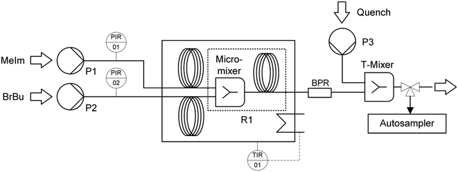 | ||
| Fig. 1 Microreactor setup for kinetic investigations, including syringe pumps (P1, P2, P3), the reactor unit (R1), and a back pressure regulator (BPR). | ||
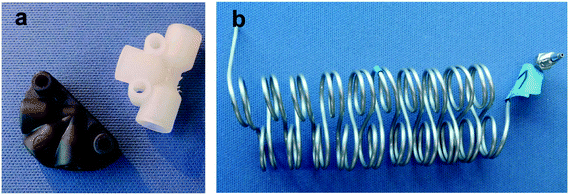
The reactants 1-methylimidazole (MeIm) and 1-bromobutane (BrBu) were preheated in 1/16 in capillaries (inner diameter (i.d.) 1 mm, capillary length 2 m) and mixed in a static mixer with an arrowhead channel configuration (Fig. 2a; static mixing tee U-466, IDEX Health & Science, Oak Harbor, WA, USA). In the central channel (i.d. 500 μm) of this mixer, homogenization of the reactants is supported by a 10 μm frit made of ultra-high-molecular-weight polyethylene. The mixer was chosen because of its moderate pressure drop and high mixing performance in the applied flow velocity range.35–37 Two different 1/16 in stainless steel capillaries (i.d. 1 mm) were used as residence time modules. For short residence times (16–189 s), a 2 m long capillary reactor (reaction volume 1.57 mL) was connected to the mixer. Longer residence times (151–754 s) for higher conversions were realized in an 8 m long capillary reactor (reaction volume 6.28 mL). The use of residence time modules with different sizes instead of only one reactor reduced the range of applied flow rates to within practical operating conditions (0.5–6.0 mL min−1). With higher flow rates, the pressure drop in the longer reactor would increase above the limit of the syringe pumps (pmax = 1200 kPa). Thus, the shorter reactor (length 2 m) was chosen to determine conversions with short reaction times. Both residence time modules were constructed as helical coils (curvature radius 8 mm) with an alternating change in the direction of curvature, which was repeated every two coils (Fig. 2b). A 700 kPa back pressure regulator (BPR P-465, IDEX Health & Science) was used to maintain an elevated pressure in the reactor system at different flow rates. Temperature control of preheating and reactor capillaries was achieved in a bath thermostat. To stop the reaction precisely after an adjusted residence time, a continuous quench was realized with a second static T-type mixer (Fig. 2a, i.d. 500 μm) at the reactor outlet. A quenching solution of acetonitrile containing acetic acid (16% volume fraction) was supplied at a flow rate ratio of 10![[thin space (1/6-em)]](https://www.rsc.org/images/entities/char_2009.gif) :
:![[thin space (1/6-em)]](https://www.rsc.org/images/entities/char_2009.gif) 1. Quenched samples were collected with an automatic sampler (Autosam, HiTec Zang GmbH, Herzogenrath, Germany). The continuous feed and quenching streams were supplied by syringe pumps (Syrdos 2, HiTec Zang GmbH). Sampling, temperature, and flow rate settings were controlled with a laboratory automation system (LabBox and LabVision Software, HiTec Zang GmbH). Analyses of the quenched samples were performed with a high-performance liquid chromatography system (Agilent 1100 series, Agilent Technologies, Palo Alto, CA, USA) with a LiChrospher RP-18 separation column and an UV detector (signal detection at 210 nm). For sample preparation, 25 μL of each sample was taken and diluted with a 1
1. Quenched samples were collected with an automatic sampler (Autosam, HiTec Zang GmbH, Herzogenrath, Germany). The continuous feed and quenching streams were supplied by syringe pumps (Syrdos 2, HiTec Zang GmbH). Sampling, temperature, and flow rate settings were controlled with a laboratory automation system (LabBox and LabVision Software, HiTec Zang GmbH). Analyses of the quenched samples were performed with a high-performance liquid chromatography system (Agilent 1100 series, Agilent Technologies, Palo Alto, CA, USA) with a LiChrospher RP-18 separation column and an UV detector (signal detection at 210 nm). For sample preparation, 25 μL of each sample was taken and diluted with a 1![[thin space (1/6-em)]](https://www.rsc.org/images/entities/char_2009.gif) :
:![[thin space (1/6-em)]](https://www.rsc.org/images/entities/char_2009.gif) 1 mixture of acetonitrile and aqueous phosphate buffer solution (5 mM, pH 7) in a volume ratio of 1
1 mixture of acetonitrile and aqueous phosphate buffer solution (5 mM, pH 7) in a volume ratio of 1![[thin space (1/6-em)]](https://www.rsc.org/images/entities/char_2009.gif) :
:![[thin space (1/6-em)]](https://www.rsc.org/images/entities/char_2009.gif) 400. The injection volume was 25 μL. The mobile phase contained acetonitrile (HPLC grade) and an aqueous phosphate buffer solution (5 mM) which were continuously mixed at a flow rate ratio of 3
400. The injection volume was 25 μL. The mobile phase contained acetonitrile (HPLC grade) and an aqueous phosphate buffer solution (5 mM) which were continuously mixed at a flow rate ratio of 3![[thin space (1/6-em)]](https://www.rsc.org/images/entities/char_2009.gif) :
:![[thin space (1/6-em)]](https://www.rsc.org/images/entities/char_2009.gif) 7. After 4.5 min, a gradient was applied to increase the acetonitrile percentage from 30% to 80% within 30 s. This ratio was held for the rest of the run.
7. After 4.5 min, a gradient was applied to increase the acetonitrile percentage from 30% to 80% within 30 s. This ratio was held for the rest of the run.
Scale-up experiments
Scale-up experiments were performed in a setup (Fig. 3) with laboratory equipment (pumps, thermostat, automation system) equivalent to that previously described for the microreactor experiments. The BrBu feed was divided for multi-injection operation and supplied by two separate syringe pumps (P2 and P3 in Fig. 1) with equal flow rates. The heat carrier cycle was realized by connecting the reactor to a thermostat (Ministat 230, Peter Huber Kältemaschinenbau AG, Offenburg, Germany). A millistructured heat exchanger/reactor was designed to fulfill the requirements for mixing, reaction, and temperature control. The reactor was manufactured as a plate reactor with three aluminum plates (AlZnMgCu1.5; 241 mm × 145 mm × 20 mm) layered one on top of the other. The structures for mixing and residence time channels were milled into the middle reactor plate (Fig. 4). On the opposite side of the middle plate, heat carrier channels (3 mm × 10 mm) were milled. Inlet and outlet connections for the reaction medium and heat carrier were located at the lateral surface of the middle reactor plate and connected to the channels via bore holes. For temperature measurement of the in- and outflowing fluids, Pt100 resistance thermometers were inserted directly into the bore holes (Fig. S1†). The top and bottom plates were face milled and used to cover the channels on both sides of the middle reactor plate. To avoid bypass flow between the channels, numerous screws were used to apply equal pressure between the plates. The reactor was sealed with polytetrafluoroethylene-coated O-rings (Brammer GmbH, Karlsruhe, Germany).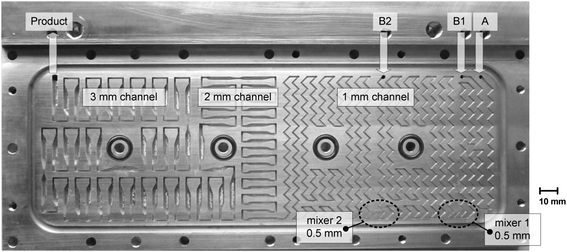 | ||
| Fig. 4 Reaction channel structure of the plate heat exchanger/reactor used for the scale-up experiments. | ||
Another residence time reactor (R2 in Fig. 3) was added to the setup in some scale-up experiments to increase the total conversion. Because of the low reaction rate and low heat release potential at high MeIm conversion (XMeIm = 90–95% at the outlet of the plate reactor R1 in Fig. 3), a high reactor volume was required, whereas reactor cooling was no longer a critical aspect. Thus, a polytetrafluoroethylene tube (i.d. 5 mm, length 1 m) was used and heated in a temperature-controlled oil bath. Compared with the experiment conducted with only the plate reactor, addition of the residence time reactor increased the total reaction volume by a factor of 2.2. Static mixing elements (ESSKA, Hamburg, Germany) were inserted throughout the entire length of the tube to improve radial mixing in laminar flow.
The reaction channel design of the plate reactor (Fig. 4) followed scale-up considerations as discussed below (‘Scale-up’ section). The reactor was divided into three sections with stepwise increases in the channel dimensions (channel widths of 1 mm, 2 mm, and 3 mm), each with a quadratic cross section. Channel structure elements with a zigzag pattern (1 mm channel) and recurring flow redirection combined with tapering to a width of 1 mm (2 mm and 3 mm channels) were implemented to enhance heat and mass transfer in laminar flow. Details of the channel structure design and specifications are given in the ESI† (Tables S1 and S2). Reactants were preheated in 1 mm channels (0.2 m length for each reactant) and mixed in an arrowhead mixing structure with a smaller cross-sectional area (0.5 × 0.5 mm2). Inclusion of an additional inlet and a second mixer in the 1 mm-wide zigzag channel section allowed for the reactor to be used as a multi-injection reactor.
Kinetic investigations in capillary reactors
Reactor model
Solvent-free mixing of MeIm and BrBu in an equimolar ratio (cMeIm,0/cBrBu,0 = 1) results in a single, homogeneous reaction phase. However, as the reaction proceeds, a second, [BMIM]Br-rich product phase is formed when an MeIm conversion between 5% and 10% is exceeded. The compositions of the individual liquid phases were investigated in preliminary experiments by immediately separating both phases at the reactor outlet instead of quenching the product. As can be seen from the resulting ternary phase diagram (Fig. S2†), MeIm is highly soluble in the product [BMIM]Br, whereas the solubility of BrBu in the product is low (mole fraction approx. 10%). At a MeIm conversion between 90% and 95%, the concentration of BrBu falls below the solubility limit and a single phase can be obtained at the reactor outlet.In a capillary reactor, the reaction phase and product phase form a typical liquid–liquid slug flow pattern (Fig. 5). Because of the ongoing formation of [BMIM]Br, the volume ratio between the reaction and product phases decreases as the phase segments travel through the reactor. A model of this two-phase behavior is key for reliable reactor simulations. Große Böwing et al.21 proposed a model for solvent-free two-phase syntheses of 1-butyl-3-methylimidazolium chloride. The two-phase behavior in this system should be similar to that for syntheses of [BMIM]Br. In their model, the authors ignored the concentration of 1-chlorobutane in the product phase because of its low solubility. Thus, MeIm conversion could only occur in the reaction phase. The partitioning equilibrium for MeIm was established according to Nernst's law. In the general mass balance for a plug flow reactor (eqn (6)), the influence of an increasing passive volume fraction on the overall reaction rate can be expressed by the correction factor ![[V with combining dot above]](https://www.rsc.org/images/entities/i_char_0056_0307.gif) rp/
rp/![[V with combining dot above]](https://www.rsc.org/images/entities/i_char_0056_0307.gif) ges (eqn (7)).
ges (eqn (7)).
 | (6) |
 | (7) |
 | ||
| Fig. 5 Schematic representation of the modeled transport processes in the liquid–liquid reaction system. | ||
The model developed by Große Böwing et al. was applied to a low temperature synthesis of 1-butyl-3-methylimidazolium chloride with a reaction time longer than 80 h. In this time frame, heat and mass transfer are negligible factors. To adapt the model to rapid high-temperature syntheses of [BMIM]Br, we extended it using additional heat and mass transfer equations. Transport processes in the liquid–liquid reaction system are shown schematically in Fig. 5. Mass transfer of MeIm between the two phases is expressed by the kla value. The heat transfer in an externally cooled reactor depends on the overall heat transfer coefficient (kw).
Eqn (8) describes local changes in the MeIm amount in the reaction phase, which result from both chemical reactions and mass transfer via the phase boundary. By adding the heat balance (eqn (9)), the influence of local hot spots on the reaction rate can be taken into account.
 | (8) |
 | (9) |
Based on the local flow rate of MeIm located in the reaction phase (ṅMeIm,rp), the phase-specific concentrations and phase volumes were calculated (eqn (S1)–(S15), ESI†). Because of the complex nature of the liquid–liquid reaction system, we made the following assumptions:
- The reactor model was based on ideal plug flow. Good approximation could be achieved if axial dispersion is neglected because back mixing in the liquid–liquid slug flow pattern is minimal.
- Single-phase reaction regimes were not considered in the model. This may lead to underestimation of the overall reaction rate at high conversions (XMeIm > 95%).
- Because of the low solubility of BrBu in the ionic liquid, any reactions occurring in the product phase were neglected. The product phase was regarded as a passive volume fraction.
- An instantaneous transition of the formed product into the reaction phase was assumed. Analyses of the separated reaction phase showed it contained almost no [BMIM]Br.
- The kla and the kw values were not a function of the residence time in the reactor. The influence of the changing phase segment lengths (i.e., change of phase boundary interface and of circulation within the slugs) was neglected.
- Temperature changes mainly affect the reaction rate. Influences on the other rate constants (kw and kla) were not taken into account. Material properties (density, heat capacity, and thermal conductivity) were calculated as a function of the local fluid temperature.
- Temperature differences between adjacent phase segments were not captured by the model equations. Because of internal circulation, we presumed rapid heat transfer occurred via the phase boundary.
Investigation of mass transfer limitations
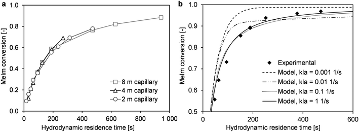
In high-temperature ionic liquid synthesis, short reaction times in the range of minutes or only a few seconds can occur. Because the decreased MeIm concentration in the reaction phase causes mass transfer via the phase boundary, the overall conversion rate may be limited by this transport process. In microreactor experiments with liquid–liquid slug flow, the mass transfer coefficient kla can be varied by changing the flow velocity.38 An increase in flow velocity intensifies mass transfer, which is determined by internal circulation in both phase segments. To obtain comparable reaction times at different flow velocities, three capillary reactors with different lengths (2 m, 4 m, and 8 m) were used in the described microreactor setup (Fig. 1). Conversion–time curves were determined for a similar range of hydrodynamic residence times. The experimental data did not show the applied flow velocity greatly affected the reaction progress (Fig. 6a).Further insights into the interaction of mass transfer and the reaction can be provided by simulations with the previously described reactor model. Our main objective was to estimate the fundamental influence of kla. For this purpose, the reaction progress was simulated with kla values that differed by several orders of magnitude (Fig. 6b and 7). The results were compared with experimentally determined conversions from the microreactor experiments (T = 110 °C, cMeIm,0/cBrBu,0 = 1) (Fig. 6b). According to the simulations, low kla values have a large effect on the overall conversion rate. However, depending on the local conversion rate, the limited mass transfer can either accelerate or decelerate the rate of conversion. At low conversions, an inhibited MeIm transfer rate (reaction phase to product phase) prevents the reactant from passing into the newly-formed passive product phase. Thus, the reaction is faster because of the higher concentration of reactants and larger reaction volume. However, when MeIm is nearly fully converted in the reaction phase (high overall conversion rate), any MeIm, which is dissolved in the product phase up to this point, is transferred in the reverse direction (product phase to reaction phase). At this final stage of the reaction, the overall conversion rate is equal to the mass transfer rate.
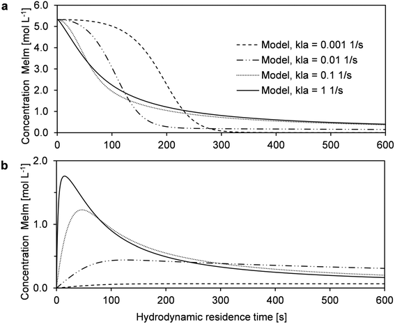 | ||
| Fig. 7 Simulations of the MeIm concentration in the reaction phase (a) and product phase (b) to demonstrate the influence of kla on the reaction rate. | ||
Using the model for fitting to the experimental data via the least sum of squares method, the best fit was obtained with the highest kla value (Fig. 6b). For kla > 0.1 s−1, the curve approaches the behavior of a reaction without mass transfer, and changes in the conversion–time curve can be neglected. For very low kla-values (kla < 0.001 s−1), an opposite limit is reached: Practically no MeIm is transferred into the passive product phase (Fig. 7b). Thus, a fast and nearly complete reaction in the reaction phase is possible in theory, regardless of the simultaneous formation of an ionic liquid.
As a result, the simulations show that both acceleration of the reaction rate at low conversion rates and stagnation at high conversion rates can be indications for mass transfer limitation in this liquid–liquid reaction system. Because both characteristics were not found in the determined time–conversion curves, we can assume the reaction process is predominant kinetically controlled.
Kinetic parameters
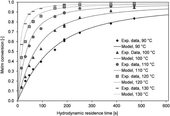
Conversion–time curves were determined in the microreactor setup between 90 and 130 °C. As described above (section ‘Microreactor experiments’), using two different capillary reactors (lengths of 2 m and 8 m) covers a large conversion range. For the transition range at a hydrodynamic residence time of 180 s, the conversion was determined with both reactors. Large deviations between those values could be assigned to the different flow velocities in the capillary reactors. However, only minor deviations were observed (Fig. 8).According to the previously described considerations of mass transfer, the kla value was defined as 1 s−1, which corresponds to a system without mass transfer limitations. By contrast, heat transfer may strongly influence the conversion at high reactor temperatures. However, it is almost impossible to determine the overall heat transfer coefficient. Internal slug circulation, changing slug length, and increases in the viscosity may lead to strong discrepancies within the reactor volume. For simplification, a constant kw value was used for the simulation. With this assumption, the best agreement between the simulated and measured conversion–time curves was obtained for kw = 1300 W m−2 K−1. The kinetic parameters and the Nernst coefficient (K) were determined via least squares fitting from the experimental data. The kinetic rate constant (k) was determined at different temperatures and used to derive the activation energy (EA) from the Arrhenius equation (Fig. S3†). The kinetic parameters obtained were k100°C = 2.22 × 10⁻⁶ L mol−1 s−1 and EA = 80.8 kJ mol−1. For each temperature, the simulated time–conversion curve agreed with the experimental data (Fig. 8).
We only considered temperature dependency for the reaction rate, but the temperature dependency of other parameters (e.g., kw and kla) may also influence the EA. The parameters determined are model parameters not physical quantities. The model can be used for predictions with different reactor scales and operation parameters. Transfer to different systems (e.g., single-phase reaction in a solvent) would require further experimental investigations.
Scale-up
Discussion of scale-up concepts
The main objective of the reactor scale-up was to develop a process that allowed for [BMIM]Br production with a high overall conversion (XMeIm > 98%) and much higher flow rates than in the microreactor experiments. For the solvent-free procedure, stable reactor operation and avoidance of large hot spots are crucial for the scale-up.28 A millistructured plate reactor was designed that combined the mixing, reaction, and heat carrier channels in one compact heat exchanger/reactor. Selection of a suitable scale-up concept allowed for maintenance of high reactor temperatures in the microreactor experiments (90–130 °C). To enable high reactor throughput at a moderate pressure drop, the scale-up involved the transfer to larger channel diameters than in the microreactor experiments. Changes in heat and mass transfer performance were estimated before designing the reactor channels. Because the cooling intensity (eqn (3)) shows a quadratic dependence on the hydraulic diameter, the focus of reactor design was to obtain controlled and stable reactor operation. Fig. 9 shows a graphical representation of eqn (2) and (5) in a dimensionless stability diagram (Fig. 9a) and an operating diagram (Fig. 9b). Assuming the reaction was solely based on chemical kinetics taking place in a homogeneous reaction system, the curves (n = 2) were used to separate stable reactor operating conditions from the instable range where high parametric sensitivity may occur. We used the described model of the liquid–liquid reaction system to establish if formation of the product phase had to be taken into account for stability considerations. Therefore, temperature profiles were calculated for different reactor diameters. Subsequently, the critical reactor temperature was determined by applying the stability criterion = 1.2. A comparison between models showed that the numerical calculation with the two-phase reactor model yielded a higher hot spot than the single-phase model. This can be explained by the fast “separation” of insoluble product from the reaction phase, which results in higher concentrations and reaction rates. Thus, the simplified correlation for a second-order reaction (eqn (5) with B = 4.57) may lead to underestimation of parametric sensitivity. To estimate the impact of this effect, the stability limit was determined from a numerical simulation with the two-phase reactor model. The stability limit was calculated by increasing the wall temperature until the criterion ΔT′ = 1.2 was reached.31 This procedure was repeated for different channel diameters (0.25–4.0 mm, Fig. S4†). The results were plotted in an operating diagram (Fig. 9b) and transferred to a dimensionless Semenov diagram (Fig. 9a). A slight shift of the critical parameters towards a lower reaction order (n = 1) was observed compared with the curve obtained using eqn (2). Given that the curve between stable and instable reactor operation represents a transition range instead of a sharp boundary, the simplified model with n = 2 is a good approximation. For conservative estimation of heat removal, the calculations were based on a Nusselt number (Nu) of 3.66 for fully-developed laminar flow and a constant wall temperature. The critical channel diameters for higher Nusselt numbers can be easily derived using the correlation
  in eqn (5).
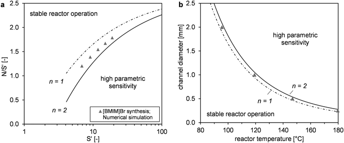 | ||
| Fig. 9 Reactor stability diagrams in dimensionless form (a) and with practical operating parameters (b). Comparison of simulated results (two-phase model) with the empirical correlation based on Baerns and Renken31 for first- and second-order reactions (single-phase model). | ||
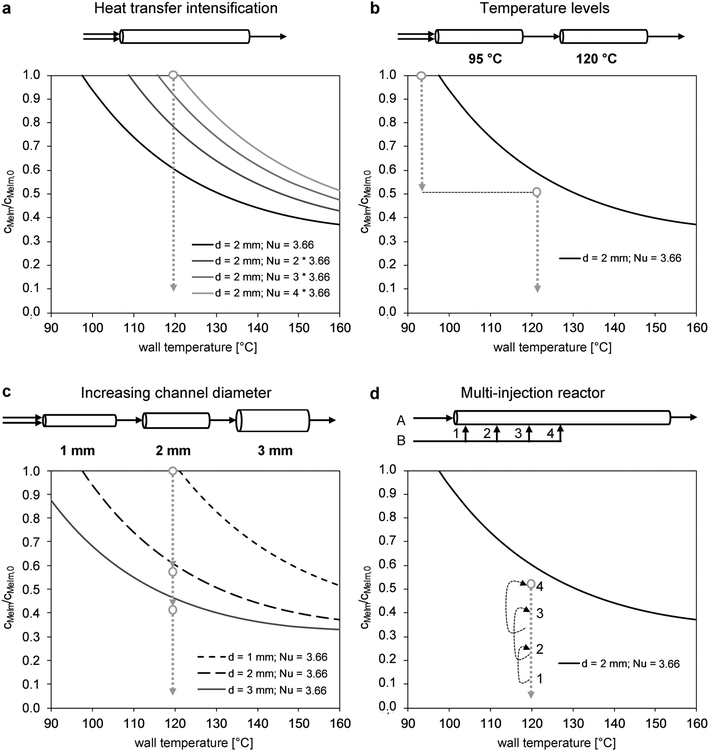
The reaction progress was visualized for different scale-up concepts in concentration–temperature operating diagrams (Fig. 10). Mathematical derivation of the curves based on the correlation by Baerns and Renken31 (eqn (2)) is described in detail by Gelhausen et al.39 The general influence of the intensification of heat transfer in the reactor channel (Nusselt number) is shown in Fig. 10a. For example, reactor operation in a 2 mm-channel with a 120 °C wall temperature would require a fourfold increase of the typical laminar flow Nusselt number (Nu = 4 × 3.66 = 14.64). An alternative approach for scale-up is the design of a reactor with two temperature stages (Fig. 10b). In the lower temperature stage (e.g., 95 °C), stable reactor operation at high concentrations can be performed. In the second stage, the decreasing reaction rate at high reactant conversions is accelerated by a temperature increase to 120 °C. However, the use of two temperature steps increases the process complexity. A similar and easier approach uses a stepwise increase in the channel diameter (Fig. 10c). A 1 mm channel is only used for the critical range at low conversion and high reaction rates. Once the maximum temperature at the main hot spot is reached, the channel diameter is enlarged to obtain the required residence time. In the multi-injection reactor concept (Fig. 10d), one of the reactants (e.g., MeIm) is injected at different locations in the reaction channel. Consequently, a lower initial concentration is obtained. An operating range below the boundary towards parametric sensitivity can be realized by adjusting the channel sections to the expected reaction progress.
Reactor design and simulation
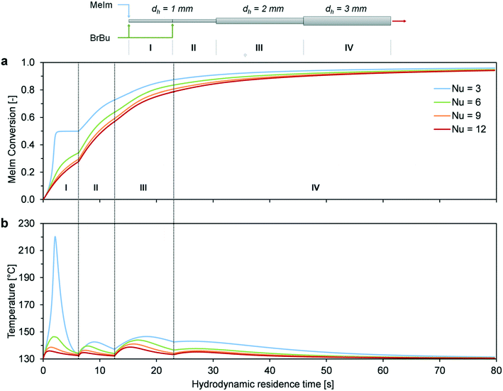
The preliminary considerations for the scale-up concepts in Fig. 10 illustrate that a reactor temperature above 120 °C cannot be achieved easily with channel diameters larger than 1 mm. Thus, a combination of different reactor concepts was considered. The channel structure of the millistructured plate reactor was designed using three of the four previously discussed scale-up concepts. A combination of heat transfer intensifying channel structures (Fig. 10a), different sections with increasing channel diameters (Fig. 10c), and multi-injection operation (Fig. 10d) was used to optimize the reactor control for high-temperature synthesis (Fig. 4). In the critical hotspot of the reactor, two mixers (0.5 mm, arrowhead design) were implemented to inject one of the reactants into the 1 mm reaction channel. In the region of higher conversion, the channel has 2 × 2 mm2 and 3 × 3 mm2 structural elements to enlarge the total reactor volume. A zigzag channel design in the 1 mm channel was chosen to enhance heat and mass transfer. In the subsequent 2 and 3 mm sections, repeated narrowing to a 1 mm channel width was combined with 90° flow redirections. The channel structures were designed to improve heat and mass transfer perpendicular to the direction of flow and to avoid dead zones in the reactor channels. Results of CFD simulations of single phase flow (Fig. S5–S7, ESI†) contributed to the optimization of the geometrical details of the channel structures. The mixing performance of the arrowhead mixers was experimentally examined with a mixing sensitive test reaction.40,41 Fig. S8 (ESI†) shows that the mixing performance of the specifically designed arrowhead mixer is even higher compared to the microreactor setup because of the higher flow velocity in the millistructured plate reactor. Based on this approach for characterization, we assumed that neither backmixing in the reactor channels nor a poor mixing performance of the arrowhead mixers has a rate limiting influence on the reaction process. Thus, the model derived from microreactor experiments was directly transferred for the calculation of the plate reactor.The choice of channel lengths was based on the reactor simulations for the different sections (Fig. 11). Calculations were performed for the aimed reactor operation with a wall temperature of 130 °C and a total flow rate of 10 mL min−1. Because of sudden changes in diameter and concentration (multi-injection), separate hot spots occurred for each channel section. The distribution of heat release among the sections depended on the degree of heat transfer intensification. Because of the complexity of the system, a detailed determination of the actual Nusselt number was not possible. The heat transfer varies throughout the reactor channel length because of viscosity increases, changes in the two-phase flow pattern, and multiple transitions to different channel structural elements. Furthermore, heat transfer in a reactive system can deviate largely from that in an unreactive system.42 For this reason, parameter variation with Nusselt numbers over a wide range seems to be the best way to discuss different degrees of heat transfer intensification. Assuming the worst-case scenario (Nu = 3, straight laminar flow without heat transfer intensification), runaway behavior was predicted in the first channel section. However, with the assumption that the channel structure and internal slug flow circulation enhanced the Nusselt number by a factor of two or higher, our simulation showed a comparatively equal distribution of hot spot formation (Nu = 6–12).
Hence, we can conclude that stable reactor operation at 130 °C is possible because of the combination of scale-up concepts, provided that strong heat transfer enhancement is obtained. In the two-phase system, enhancement can result from internal circulation in the phase segments,43,44 which can be further intensified by 90° redirections in the zigzag channel.45 To verify the scale-up concept, we performed experimental investigations of high-temperature synthesis in the reaction-adapted plate reactor.
Scale-up experiments
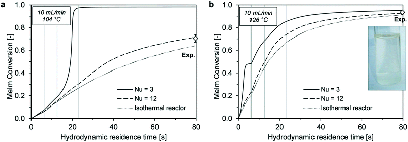
In a comparison between simulations and experiments, the main criterion was agreement of MeIm conversion determined at the reactor outlet with the corresponding calculated values. Because high temperatures result in strong discoloration,26 product color can be an additional indicator of local hot spots.Before conducting the experiment in the target temperature range (120–130 °C), an additional experiment was performed with a much lower reactor temperature (104 °C). At this temperature, the final conversion was more sensitive to the reactor performance and a wider conversion range could be covered for the experimental validation. Experimentally determined conversions were compared with simulated time–conversion curves (Fig. 12). Because the Nusselt number is an unknown parameter, simulations with minimum heat transfer intensification (Nu = 3), strong heat transfer intensification (Nu = 12), and maximum intensification (isothermal reactor) were compared. A value of Nu = 3 resulted in runaway behavior. At a lower reaction temperature (104 °C, Fig. 12a), thermal runaway occurred in section III because of transition to the 2 mm channel. The lower reaction rate at lower temperature ensures stable reactor control in the 1 mm channel; however, it does not provide sufficient conversion for avoiding runaway with larger channel widths. The experimentally determined conversion indicates that reactor behavior is much closer to that of an isothermal reactor (Fig. 12a).
For the high-temperature experiment (126 °C, Fig. 12b), the simulated outlet conversions showed small deviations from the behavior with Nu = 3 and isothermal conditions. A nearly colorless ionic liquid was obtained at the reactor outlet, which supported the assumption of high reactor control without extreme temperature peaks in the case of reaction runaway (Fig. 11b, Nu = 3).
In the experiments with the plate reactor, a total conversion of XMeIm = 93% was obtained. To increase the reactant conversion in continuous production, a residence time reactor was added to the reactor setup (Fig. 3). Because of the low reactant concentrations, heat transfer requirements were low for this reactor. Thus, a 5 mm tube reactor with static mixing elements could be used to increase the residence time from 78 s to 172 s at a flow rate of 10 mL min−1. In the experiment, a total reactor conversion of XMeIm = 98% was determined at the outlet of the residence time reactor. The achieved production rate of 0.456 kg h−1 is at the upper end of the throughput range that has been described in previous literature on continuous ionic liquid production23,28,46 (0.05–0.5 kg h−1). Because our reactor design and scale-up approach was strongly focused on thermal reactor stability, we could increase the reaction temperature (126 °C) significantly above typical reaction conditions of the [BMIM]Br synthesis.28,46 For this reason, shorter reaction times and higher space time yields (S.T.Y.) were obtained. However, a direct comparison of the S.T.Y. between different studies may be misleading if they are based on different requirements for the total reactant conversion. For XMeIm > 90%, the aimed conversion is a main factor for the required reactor volume. Regarding the reactor by itself, the S.T.Y. achieved in this work was 32.5 kg h−1 L−1 (XMeIm = 93%). In combination with the residence time reactor tube, it decreased to 10.7 kg h−1 L−1 (XMeIm = 98%).
Conclusions
The described microreactor setup allows for kinetic investigations under clearly defined reaction conditions. The experimental results obtained with coiled capillary reactors provide a basis for a model to describe conversion and temperature profiles of solvent-free [BMIM]Br synthesis in flow reactors. The model equations include the formation of a two-phase liquid–liquid system in the slug flow regime. Continuous decreases in the volume ratio between the reaction and product phases during the reaction are taken into account. Despite the assumptions applied for simplification, this model shows good agreement between simulated curves and experimental data. Because short reaction times in the range of several seconds are achieved with reactor temperatures above 100 °C, integration of the MeIm mass transfer rate between both fluid phases provides a substantial improvement over earlier models. The results obtained with variation of kla increase our understanding of the interaction between the reaction and mass transfer, and enable differentiation between mass transfer limitations and kinetically-determined conversion curves.Continuous synthesis of [BMIM]Br in a scaled-up millistructured heat exchanger/reactor was realized at elevated temperatures close to the transition to thermal runaway. Thus, controllability of the reactor has to be assured and calculation of thermal reactor behavior is of crucial importance. The presented scale-up approach is based on a stability evaluation that is derived from simulation of temperature profiles in the reactor. The stability criterion ΔT′ = 1.2 was applied for the reactor model and transferred to practical operating diagrams. Based on numerical simulation, a targeted adaption of the channel structure can limit the extent of local hot spots and prevent thermal runaway. The described approach shows the advantage of a detailed kinetic model for developing a channel design for a reaction-specific optimized reactor.
In the final scale-up validation experiment with a plate reactor and an additional residence time reactor, thermally stable and continuous production of an ionic liquid at a reactor throughput of 0.456 kg h−1 and temperature of 126 °C gave a total MeIm conversion of 98%. The product was pure with low discoloration. In addition to the high material efficiency, a further positive of process intensification is the avoidance of energy-intensive purification, which results from solvent-free operation with a stoichiometric initial reactant ratio.
Notation
| a f | Thermal diffusivity, af = λ/(ρcp) (m2 s−1) |
| A w | Wetted surface area (m2) |
| c j | Concentration of component j (mol m−3) |
| c j,0 | Theoretical initial concentration of component j in the reaction mixture (mol m−3) |
| c p | Heat capacity of the fluid (J kg−1 K−1) |
| d h | Hydraulic channel diameter (m) |
| E A | Activation energy of the reaction (J mol−1) |
| ΔHR | Enthalpy of reaction (J mol−1) |
| k | Rate constant of the reaction, nth-order (Ln−1 mol1−n s−1) |
| k l a | Volumetric mass transfer coefficient (s−1) |
| k w | Overall heat transfer coefficient (W m−2 K−1) |
| N | Time ratio of reaction and cooling (dimensionless) |
| ṅ | Molar flow rate (mol s−1) |
| Nu | Nusselt number (dimensionless) |
| r | Reaction rate (mol m−3 s−1) |
| R | Universal gas constant (8.314 J mol−1 K−1) |
| S′ | Heat production potential (dimensionless) |
| t c | Characteristic time scale of cooling (s) |
| t r | Characteristic time scale of the reaction (s) |
| T | Temperature (K) |
| T w | Wall temperature (K) |
| ΔT′ | Dimensionless temperature difference |
| ΔTad | Adiabatic temperature increase (K) |
| u | Axial flow velocity (m s−1) |
| V r | Reactor volume (mL) |
![[V with combining dot above]](https://www.rsc.org/images/entities/i_char_0056_0307.gif)
| Volumetric flow rate (m3 s−1) |
| X MeIm | Conversion of 1-methylimidazole (dimensionless) |
| z | Axial distance from the reactor inlet (m) |
Greek symbols
| α | Heat transfer coefficient (W m−2 K−1) |
| γ | Arrhenius number (dimensionless) |
| λ | Heat conductivity of the fluid (W m−1 K−1) |
| ρ | Density of the fluid (kg m−3) |
Conflicts of interest
There are no conflicts to declare.Acknowledgements
This work was funded by the German Federal Ministry of Education and Research (BMBF) as part of the program “IngenieurNachwuchs – Forschung an Fachhochschulen” (Grant No. 03FH012I2) and as part of the Innovation Partnership M2Aind, project SM2all (Grant No. 13FH8I01IA) within the framework “Starke Fachhochschulen – Impuls für die Region” (FH-Impuls).References
- P. Wasserscheid and T. Welton, Ionic Liquids in Synthesis, Wiley-VCH, Weinheim, 2003 Search PubMed.
- D. A. Waterkamp, Dissertation, Universität Bremen, 2012 Search PubMed.
- H. Zhao, S. Xia and P. Ma, Use of ionic liquids as ‘green’ solvents for extractions, J. Chem. Technol. Biotechnol., 2005, 80, 1089–1096 CrossRef CAS.
- M. J. Earle and K. R. Seddon, Ionic liquids, Green solvents for the future, Pure Appl. Chem., 2000, 72, 1391–1398 CAS.
- A. Jess, A. Große Böwing and P. Wasserscheid, Kinetik und Reaktionstechnik der Synthese ionischer Flüssigkeiten, Chem. Ing. Tech., 2005, 77, 1430–1439 CrossRef.
- T. Welton, Room-Temperature Ionic Liquids, Solvents for synthesis and catalysis, Chem. Rev., 1999, 99, 2071–2084 CrossRef CAS PubMed.
- T. Welton, Ionic liquids in catalysis, Coord. Chem. Rev., 2004, 248, 2459–2477 CrossRef CAS.
- H. Olivier-Bourbigou and L. Magna, Ionic liquids, J. Mol. Catal. A: Chem., 2002, 182–183, 419–437 CrossRef CAS.
- B. J. Reizman and K. F. Jensen, Feedback in Flow for Accelerated Reaction Development, Acc. Chem. Res., 2016, 49, 1786–1796 CrossRef CAS PubMed.
- S. Mozharov, A. Nordon, D. Littlejohn, C. Wiles, P. Watts, P. Dallin and J. M. Girkin, Improved method for kinetic studies in microreactors using flow manipulation and noninvasive Raman spectrometry, J. Am. Chem. Soc., 2011, 133, 3601–3608 CrossRef CAS PubMed.
- I. M. Mándity, S. B. Ötvös, G. Szőlősi and F. Fülöp, Harnessing the Versatility of Continuous-Flow Processes: Selective and Efficient Reactions, Chem. Rec., 2016, 16, 1018–1033 CrossRef PubMed.
- B. P. Mason, K. E. Price, J. L. Steinbacher, A. R. Bogdan and D. T. McQuade, Greener approaches to organic synthesis using microreactor technology, Chem. Rev., 2007, 107, 2300–2318 CrossRef CAS PubMed.
- V. Hessel, D. Kralisch, N. Kockmann, T. Noël and Q. Wang, Novel Process Windows for Enabling, Accelerating, and Uplifting Flow Chemistry, ChemSusChem, 2013, 6, 746–789 CrossRef CAS PubMed.
- I. M. Mándity, S. B. Ötvös and F. Fülöp, Strategic Application of Residence-Time Control in Continuous-Flow Reactors, ChemistryOpen, 2015, 4, 212–223 CrossRef PubMed.
- A. Adamo, R. L. Beingessner, M. Behnam, J. Chen, T. F. Jamison, K. F. Jensen, J.-C. M. Monbaliu, A. S. Myerson, E. M. Revalor, D. R. Snead, T. Stelzer, N. Weeranoppanant, S. Y. Wong and P. Zhang, On-demand continuous-flow production of pharmaceuticals in a compact, reconfigurable system, Science, 2016, 352, 61–67 CrossRef CAS PubMed.
- N. G. Anderson, Using Continuous Processes to Increase Production, Org. Process Res. Dev., 2012, 16, 852–869 CrossRef CAS.
- J.-i. Yoshida, H. Kim and A. Nagaki, Green and sustainable chemical synthesis using flow microreactors, ChemSusChem, 2011, 4, 331–340 CrossRef CAS PubMed.
- C. Wiles and P. Watts, Continuous flow reactors: a perspective, Green Chem., 2012, 14, 38–54 RSC.
- N. Sen, K. K. Singh, S. Mukhopadhyay and K. T. Shenoy, On continuous, solvent-free synthesis of ionic liquid [BMIM]Br in a microbore tube, J. Radioanal. Nucl. Chem., 2016, 307, 1001–1009 CrossRef CAS.
- M. Cvjetko Bubalo, I. Sabotin, I. Radoš, J. Valentinčič, T. Bosiljkov, M. Brnčić and P. Žnidaršič-Plazl, A comparative study of ultrasound-, microwave-, and microreactor-assisted imidazolium-based ionic liquid synthesis, Green Process. Synth., 2013, 2, 579–590 Search PubMed.
- A. Große Böwing and A. Jess, Kinetics of single- and two-phase synthesis of the ionic liquid 1-butyl-3-methylimidazolium chloride, Green Chem., 2005, 7, 230–235 RSC.
- C. B. Minnich, L. Greiner, C. Reimers, M. Uerdingen and M. A. Liauw, Bridging the gap: A nested-pipe reactor for slow reactions in continuous flow chemical synthesis, Chem. Eng. J., 2011, 168, 759–764 CrossRef CAS.
- A. Renken, V. Hessel, P. Löb, R. Miszczuk, M. Uerdingen and L. Kiwi-Minsker, Ionic liquid synthesis in a microstructured reactor for process intensification, Chem. Eng. Process., 2007, 46, 840–845 CrossRef CAS.
- D. A. Waterkamp, M. Engelbert and J. Thöming, On the effect of enhanced mass transfer on side reactions in capillary microreactors during high-temperature synthesis of an ionic liquid, Chem. Eng. Technol., 2009, 32, 1717–1723 CrossRef CAS.
- J. Zimmermann, B. Ondruschka and A. Stark, Efficient synthesis of 1,3-dialkylimidazolium-based ionic liquids: the modified continuous Radziszewski reaction in a microreactor setup, Org. Process Res. Dev., 2010, 14, 1102–1109 CrossRef CAS.
- A. Stark, P. Behrend, O. Braun, A. Müller, J. Ranke, B. Ondruschka and B. Jastorff, Purity specification methods for ionic liquids, Green Chem., 2008, 10, 1152–1161 RSC.
- A. Große Böwing and A. Jess, Kinetics and reactor design aspects of the synthesis of ionic liquids—Experimental and theoretical studies for ethylmethylimidazole ethylsulfate, Chem. Eng. Sci., 2007, 62, 1760–1769 CrossRef.
- D. A. Waterkamp, M. Heiland, M. Schlüter, J. C. Sauvageau, T. Beyersdorff and J. Thöming, Synthesis of ionic liquids in micro-reactors—a process intensification study, Green Chem., 2007, 9, 1084 RSC.
- A. Varma, M. Morbidelli and H. Wu, Parametric Sensitivity in Chemical Systems, Cambridge University Press, Cambridge, 1999 Search PubMed.
- H. Wu, M. Morbidelli and A. Varma, An approximate criterion for reactor thermal runaway, Chem. Eng. Sci., 1998, 3341–3344 CrossRef CAS.
- M. Baerns and A. Renken, in Winnacker Küchler: Chemische Technik, ed. W.K.R. Dittmeyer, G. Kreysa and A. Oberholz, Wiley-VCH, Weinheim, 2004 Search PubMed.
- M. Baerns, A. Behr, A. Brehm, J. Gmehling, K.-O. Hinrichsen, H. Hofmann, U. Onken, R. Palkovits and A. Renken, Technische Chemie, Wiley-VCH, Weinheim, 2013 Search PubMed.
- S. Tadepalli, R. Halder and A. Lawal, Catalytic hydrogenation of o-nitroanisole in a microreactor, Chem. Eng. Sci., 2007, 62, 2663–2678 CrossRef CAS.
- N. Zaborenko, M. W. Bedore, T. F. Jamison and K. F. Jensen, Kinetic and Scale-Up Investigations of Epoxide Aminolysis in Microreactors at High Temperatures and Pressures, Org. Process Res. Dev., 2011, 15, 131–139 CrossRef CAS.
- L. Falk and J.-M. Commenge, Performance comparison of micromixers, Chem. Eng. Sci., 2010, 65, 405–411 CrossRef CAS.
- S. Schwolow, J. Hollmann, B. Schenkel and T. Röder, Application-oriented analysis of mixing performance in microreactors, Org. Process Res. Dev., 2012, 16, 1513–1522 CrossRef CAS.
- N.-T. Nguyen and Z. Wu, Micromixers—a review, J. Micromech. Microeng., 2005, 15, R1–R16 CrossRef.
- M. N. Kashid, Y. M. Harshe and D. W. Agar, Liquid−liquid slug flow in a capillary: an alternative to suspended drop or film contactors, Ind. Eng. Chem. Res., 2007, 46, 8420–8430 CrossRef CAS.
- M. G. Gelhausen, S. K. Kurt and N. Kockmann, Parametrische Empfindlichkeit einer stark exothermen Reaktion im Kapillarwendelreaktor, Chem. Ing. Tech., 2015, 87, 781–790 CrossRef CAS.
- J. Baldyga and J. R. Bourne, Turbulent mixing and chemical reactions, Wiley, New York, 1999 Search PubMed.
- J. R. Bourne, O. M. Kut, J. Lenzner and H. Maire, Kinetics of the diazo coupling between 1-naphthol and diazotized sulfanilic acid, Ind. Eng. Chem. Res., 1990, 29, 1761–1765 CrossRef CAS.
- S. Schwolow, J. Y. Ko, N. Kockmann and T. Röder, Enhanced heat transfer by exothermic reactions in laminar flow capillary reactors, Chem. Eng. Sci., 2016, 141, 356–362 CrossRef CAS.
- A. R. Betz and D. Attinger, Can segmented flow enhance heat transfer in microchannel heat sinks?, Int. J. Heat Mass Transfer, 2010, 53, 3683–3691 CrossRef CAS.
- V. Talimi, Y. S. Muzychka and S. Kocabiyik, Slug flow heat transfer in square microchannels, Int. J. Heat Mass Transfer, 2013, 62, 752–760 CrossRef.
- Z. Anxionnaz-Minvielle, M. Cabassud, C. Gourdon and P. Tochon, Influence of the meandering channel geometry on the thermo-hydraulic performances of an intensified heat exchanger/reactor, Chem. Eng. Process., 2013, 73, 67–80 CrossRef CAS.
- N. Sen, V. Koli, K. K. Singh, S. Mukhopadhyay and K. T. Shenoy, High throughput, continuous, solvent-free synthesis of ionic liquid [BMIM]Br in a microbore tube, Chem. Eng. Process., 2017, 121, 180–187 CrossRef CAS.
Footnote |
| † Electronic supplementary information (ESI) available. See DOI: 10.1039/c8re00148k |
| This journal is © The Royal Society of Chemistry 2019 |


