 Open Access Article
Structural, magnetic and magneto-optical studies of Mn/Al bilayer thin films on GaAs substrates
H. Khanduri *a,
Mukesh C. Dimrib,
Prashant Kumarae,
Shanu Chaudharyc,
Kritika Anandde and
R. P. Pantae
aIndian Reference Materials, CSIR-National Physical Laboratory, New Delhi-110012, India. E-mail: himani.khanduri@gmail.com
bJaypee University Anoopshahr, UP-203390, India
cAmity Institute of Applied Science, Amity University, Noida, UP-201313, India
dPhysico Mechanical Metrology, CSIR-National Physical Laboratory, New Delhi-110012, India
eAcSIR – National Physical Laboratory Campus, New Delhi-110012, India
First published on 17th December 2019
Abstract
Ferromagnetism and magnetic anisotropy in Mn–Al thin films can be of great interest due to their applications in spintronic components and as rare-earth free magnets. Temperature-dependent uniaxial anisotropy has been observed in ferromagnetic MnAl thin films, which is attributed to the modification of the tetragonal lattice distortion with the change in annealing temperature, confirmed by VSM, MOKE and XRD results; the annealing time did not affect the magnetic anisotropy. A simple evaporation technique was used to deposit the Mn/Al bilayer thin films (thickness ∼ 64 nm) on GaAs substrates. A comprehensive study of the effect of annealing temperature as well as annealing time on structural, microstructural, magnetic and magneto-optical properties are reported in this paper. The ferromagnetic phase was enriched in annealed samples, which was confirmed by XRD, MOKE and magnetic hysteresis loops. XRD results revealed that the ferromagnetic τ-phase was enhanced in annealed films with the increase in annealing temperature ≥ 400 °C. Surface roughness was estimated from the AFM micrographs and was found to be increased, whereas the mean grain size was decreased on annealing the as-deposited Mn/Al bilayer thin film. The gradual increase in magnetic coercivity was found on increasing the annealing temperature. It is interesting to note that the magnetic easy axis can be tuned by changing the annealing temperature of MnAl thin films, and the easy axis changes from perpendicular to parallel direction of the film plane when the annealing temperature varies from 400 °C to 500 °C. MOKE results were also found to be consistent with the magnetic results.
Introduction
Ferromagnetism in L10-phase MnAl has gained a lot of attention in recent years due to the large magneto-crystalline anisotropy and low cost as compared to rare earth and other Heusler alloy materials.1–4 It is well known from the phase diagram of the Mn–Al binary alloy that the τ-phase MnAl (tetragonal L10-type superstructure) is the only ferromagnetic phase in the system.3,5 The ferromagnetic τ-phase MnAl is usually achieved from the transformation of the high-temperature ε-phase into the τ-phase.6,7 Different reports on the MnAl alloys suggest that the transformation from the hexagonal ε-phase to the tetragonal τ-phase is also accompanied by nucleation, diffusion and massive transformations.8,9 The ε-phase and τ-phase of the MnAl alloy exhibited antiferromagnetic and ferromagnetic nature, respectively.10 The ferromagnetic τ-phase in the MnAl alloy is quite difficult to achieve and to stabilize at room temperature in bulk form, but it can be stabilized in thin film form.11–13 Although ferromagnetic phases in thin films of MnAl have been reported, there are still challenges in stabilizing the desired ferromagnetic single-phase MnAl films.14–16 However, once the L10-MnAl ferromagnetic phase is achieved in thin films on different semiconductor substrates, they can be utilized in heterostructures for use in spintronics, non-volatile magnetoresistive random access memory (MRAM) and ultrahigh-density recording media.17–19 Recently we reported the formation of ferromagnetic τ-phase MnAl on silicon substrates by ion irradiation, although the magnetization was quite low in those films.20 The magneto-optical Kerr effect (MOKE) is used to detect the surface magnetization of thin films with even higher sensitivity than the Superconducting Quantum Interferometer Devices (SQUID). The magneto-optical Kerr effect appears due to the reflection of a linearly polarised electromagnetic wave from a metal surface in the presence of a magnetic or electric field. After reflection from the metal surface, the polarization of the wave becomes elliptical and the rotation of the polarization is proportional to the thickness of the film and magnetization.21 The microscopic origin of MOKE is based on the combination of band exchange splitting and spin–orbit interactions.22,23 There are few reports on the deposition of Mn–Al on GaAs substrates by techniques like molecular beam epitaxy (MBE), sputtering, etc., but we planned to use a simple evaporation method for growing the layers of Mn and Al, to achieve the desired ferromagnetic τ-phase in MnAl alloy film. Therefore, we deposited the Mn/Al bilayer thin films on GaAs substrates without any buffer layer, and studied their structural, microstructural and magnetic properties. There are limited studies on the magneto-optical properties of MnAl thin films24 so we explored the longitudinal and polar magneto-optical Kerr effect (MOKE) of these thin films.In the present paper, we discuss the results of Mn/Al bilayer thin films grown on GaAs substrates by the evaporation technique at room temperature. A detailed study of the effects of annealing temperature and time on the structural, microstructural, magnetic as well as on magneto-optical properties of MnAl thin films is reported.
Experimental
Mn/Al bilayer thin films were deposited on GaAs substrates (Fig. 1(a)) by an evaporation technique at high vacuum 4.6 × 10⁻⁷ mbar. The GaAs substrates were placed around 20 cm above the target. The Mn layer was deposited on the GaAs substrate by the electron beam evaporation method at a deposition rate of 0.1 to 0.2 nm s−1. Mn pellets were prepared from Mn (99.99%) powder and used as the target for the deposition of the Mn layer. The Al layer was deposited on the Mn layer by the thermal resistive heating method at high vacuum pressure (1 × 10⁻⁶ mbar). Aluminium (99%) wire was used as a target. The deposition rate of Al was varied from 0.1 to 1 nm s−1. The thicknesses and composition of Mn and Al layers were measured by Rutherford backscattering spectrometry (RBS) using 2 MeV He ions. Since Ga and Mn are close in mass, it is not possible to separate Ga from Mn peaks in RBS spectra, using a 2–3 MeV helium beam. Therefore, we deposited the same MnAl bilayer thin film on a quartz substrate simultaneously, which was later used for RBS measurements. RBS spectra were fitted and analysed using the SIMNRA version 6.06. As-deposited thin films were annealed in argon atmosphere at temperatures of 300, 400 and 500 °C in a TAIE Jupiter PFY-400 Tubular Furnace. The annealing time for the samples treated at 300, 400 and 500 °C was one hour, whereas the film was annealed at 400 °C for 2 hours. These annealed films were named MnAl_300_1h, MnAl_400_1h, MnAl_500_1h and MnAl_400_2h, respectively. The heating rate was 5 °C per minute, and the samples were cooled to room temperature naturally inside the furnace in an argon gas atmosphere. On annealing the as-deposited bilayer film, manganese and aluminium layers were mixed together by the diffusion of Mn and Al atoms and resulted in the MnAl alloy film. The schematic crystal structure of τ-MnAl is shown in Fig. 1(b). X-ray diffraction (XRD) measurements of the as-deposited and annealed samples were carried out using a Rigaku Ultima IV with CuKα (1.5406 Å) target at a scanning speed of 2° min−1 in the 20–60° scan range with a grazing angle of 1°. The surface morphologies of the as-deposited and annealed Mn/Al bilayer thin films were studied using Atomic Force Microscopy (NanoScope Bruker). Atomic force microscopy (AFM) images were recorded at room temperature for an area of 0.5 × 0.5 μm2. Nanoscope analysis software was used to analyse the AFM results. The magnetic in-plane (applied field parallel to the film plane) and out-of-plane (applied field normal to the film plane) hysteresis loops of the films were measured at room temperature and with a maximum magnetic field of 1 tesla using VSM (Lake Shore 7410). Magneto-optical measurements were performed in longitudinal and polar mode on all samples by using NanoMOKE-III, Durham Magneto Optics Ltd with a solid-state laser of 5 mW and 660 nm. The schematic of the NanoMOKE-III system is shown in Fig. 1(c). The laser was focused onto the sample by a lens system. After passing through the lens system, the laser beam was incident along the surface normal (for polar MOKE) and at an angle of 45° to the surface normal (for longitudinal MOKE) of the samples. The reflected light was passed through an analyser and detected on a photodiode/CCD. An electromagnet was used to generate both in-plane and out-of-plane applied magnetic fields up to 1500 Oe, which varied sinusoidally at a rate of 1.5 Hz.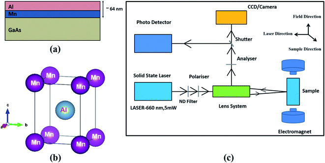 | ||
| Fig. 1 Schematic diagrams of (a) the Mn/Al bilayer thin film on a GaAs substrate, (b) the crystal structure of τ-MnAl and (c) different components of the Nano-MOKE magnetometer. | ||
Results and discussion
Compositional study (Rutherford back scattering (RBS))
The thickness and composition of the as-deposited Mn/Al bilayer thin film were calculated from the SIMNRA simulation of the observed RBS spectrum. The total thickness of the Mn/Al film was found to be around 64 nm, which was the sum of the thicknesses of the Mn layer (31 nm) and Al layer (33 nm) with the experimental errors ≤ ±10%. The atomic percentages of Mn and Al were approximately 56% and 44%, respectively, which are in the desired range (Mn = 50–60%) for the formation of the τ-phase.10Structural characterization (XRD)
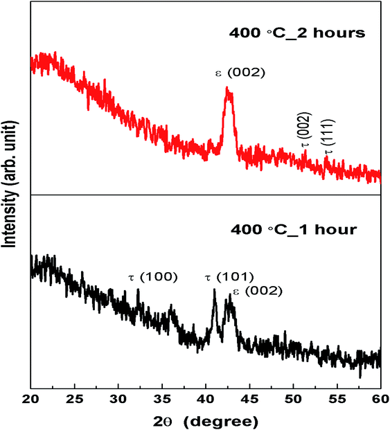
X-ray diffraction (XRD) patterns for the as-deposited and annealed MnAl bilayer films are shown in Fig. 2 and 3. Fig. 2 shows the annealing temperature effects, whereas the changes due to annealing time can be seen in Fig. 3. The different Mn–Al phases exhibited in these diffractograms for the as-deposited and annealed films are listed in Table 2. The XRD pattern of as-deposited film shows the mixture of phases (β + ε + τ),7,16 but when the films were annealed at different temperatures (300–500 °C for 1 hour), the crystal structure transformed from the ε-phase to the ferromagnetic τ-phase. After annealing the as-deposited film at 300 °C, the intensity of the ε (002) peak increased with the decrease in the intensity of the peaks of other phases. On further increasing the annealing temperature to 400 °C, τ (100) and τ (101) peaks7 appeared, whereas τ (001) and ε (002) peaks were diminished in the MnAl_400_1h thin film. The τ (001) and τ (111) peaks were enhanced for the MnAl_500_1h film with the decrease in intensity of the ε (002) peak. The ferromagnetic τ-phase of MnAl is typically achieved by controlled the cooling of the ε-phase or by quenching followed by annealing at 300–550 °C.25 On further increasing the temperature from 550 °C to 600 °C, the τ-phase decomposed into non-magnetic γ and β phases.26,27 Previous studies revealed that ferromagnetic ordering was enhanced in the MnAl thin films on increasing the annealing temperature to 500 °C.27,28 Therefore, we selected the temperature range from 300 to 500 °C to achieve the desired ferromagnetic phase. Our results are consistent with previous studies25,27,28 and suggest the enhancement of the ferromagnetic τ-phase in MnAl thin film up to the annealing temperature of 500 °C. Annealing above 500 °C was not performed in this study because of the reduction in the ferromagnetic τ-phase as already reported for annealing temperatures ≥ 550 °C.26,27 The XRD patterns for MnAl_400_1h and MnAl_400_2h films annealed for different times are shown in Fig. 3, which revealed that the τ (100) and τ (101) peaks present in the MnAl_400_1h film were diminished in the MnAl_400_2h film. The ε-phase was enhanced with the increased intensity of the ε (002) peak on annealing the sample for two hours. τ (002) and τ (111) peaks with small intensity appeared in the sample annealed for two hours. Therefore, on annealing the Mn/Al bilayer thin film for a longer time (2 hours), the ferromagnetic τ-phase was reduced and the antiferromagnetic ε-phase was enhanced. The reduction in the ferromagnetic τ-phase might be due to the fact that the τ-phase is not stable at high temperatures and it decomposes into non-magnetic phases. The effects of annealing time have also been reported by S. Zhao and group, which suggested that the longer annealing time reduced the ferromagnetic τ-phase of the Mn/Al multilayer film.14 It was also suggested in the literature that annealing the Mn/Al bilayer thin film for a longer time (>2 hours) could cause a further reduction in the ferromagnetic τ-phase. The lattice parameters, lattice strain, unit cell volume and average crystallite size (by using the Scherrer equation) of films annealed at 400 and 500 °C were evaluated from the XRD patterns and are summarized in Table 1. The ‘c/a’ ratio for MnAl_400_1h and MnAl_400_2h films (see Table 1) is very close to the bulk value (1.29), whereas the sample annealed at 500 °C has a lower c/a value (1.16). The lower ‘c/a’ ratio could be related to the increased strain in the MnAl_500_1h film.15 The XRD results revealed that the ε-phase is dominant in the MnAl_300_1h film, which was transformed into the τ-phase on further increasing the annealing temperature. Mn and Al atoms were arranged in a tetragonal distorted τ-phase structure after annealing the as-deposited Mn/Al bilayer films at 400 °C and 500 °C. It has been reported in literature that the ε-phase was transformed into the τ-phase by annealing the MnAl thin film below 500 °C.29 The enhancement of the τ-phase in the annealed films could be due to the mixing of the Mn and Al layers at higher temperatures by the diffusion of Mn and Al atoms. The in-plane and out-of-plane strains (ε) were calculated by using the formula ε = (a − a0)/a0,30 where ‘a’ is either the in-plane (a) or out-of-plane (c) lattice parameters, and a0 is the bulk unstressed lattice parameter for MnAl. Films annealed at 500 °C showed the highest out-of-plane compressive strain (ε⊥) of −0.084% and an in-plane tensile strain (ε∥) of 0.018%.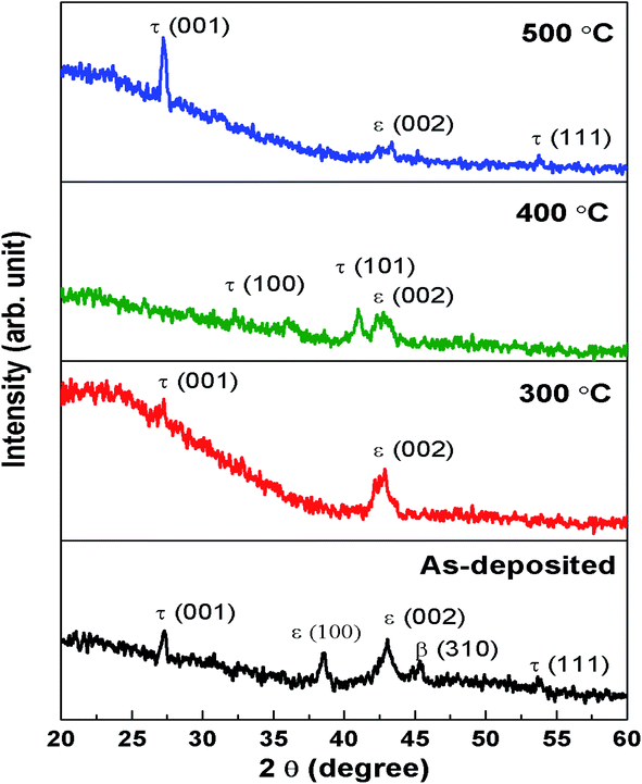 | ||
| Fig. 2 XRD patterns of Mn/Al bilayer thin films as-deposited and annealed at 300, 400 and 500 °C for one hour. | ||
| Sample name | Lattice parameters (Å) | Strain (%) | Unit cell volume (Å3) | Average crystallite size (nm) | |||
|---|---|---|---|---|---|---|---|
| a | c | ‘c/a’ | In-plane (ε∥) | Out-of-plane (ε⊥) | |||
| MnAl_400_1h | 2.77 | 3.61 | 1.30 | 0 | 0.0112 | 27.69 | 15 |
| MnAl_400_2h | 2.74 | 3.55 | 1.29 | −0.01 | −0.005 | 26.65 | 15 |
| MnAl_500_1h | 2.82 | 3.27 | 1.16 | 0.018 | −0.084 | 26.00 | 18 |
| MnAl bulk [unstressed] | 2.77 | 3.57 | 1.29 | — | — | 27.39 | — |
Microstructural (AFM) study
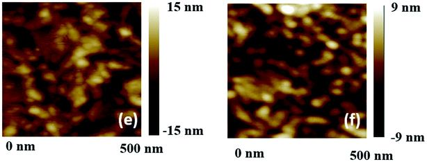
Fig. 4 shows the AFM images of as-deposited and annealed (for one hour) films. The effect of annealing time on the microstructure can be seen in Fig. 5. The surface roughness and the grain sizes estimated from these micrographs are given in Table 2. We can see that the surface roughness increased, whereas the mean grain size decreased on annealing the as-deposited film. The average grain size decreased gradually with the increase in annealing temperature and time. Similar trends for the changes in grains31,32 and crystallite32 sizes have also been observed in other studies. With the increase in the annealing temperature, the ε-phase was transformed into the ferromagnetic τ-phase and the boundaries between crystallites at which the phase transformation took place decreased in volume, which was followed by a reduction in grain size.32 The reduction in unit cell volume with the increase in the crystallite size (on annealing the film from 400 to 500 °C, Table 1) has been attributed to the strains/stresses caused by the merging of crystallites and structural modification.33 The reduction in the unit cell volume and surface reconstruction could also drive the reduction in grain size.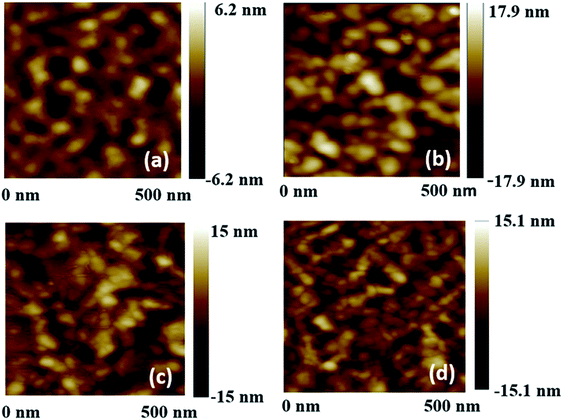 | ||
| Fig. 4 AFM images of MnAl thin films (a) as-deposited, (b) MnAl_300_1h, (c) MnAl_400_1h and (d) MnAl_500_1h. | ||
| Sample name | Phases present (from XRD) | Roughness (nm) for scanned area 0.5 × 0.5 μm2 | Mean grain size (nm) |
|---|---|---|---|
| Mn/Al bilayer (as-deposited) | β + ε + τ | 1.3 | 68 |
| MnAl_300_1h | ε + τ | 3.8 | 47 |
| MnAl_400_1h | ε + τ | 3.9 | 45 |
| MnAl_500_1h | ε + τ | 3.2 | 36 |
| MnAl_400_2h | ε + τ | 3.1 | 31 |
The roughness increased for samples annealed at 400 °C for one hour and decreased with a further increase in the annealing temperature or time. The change in the microstructure in the annealed films was due to the structural transformation of the Mn/Al bilayer film to MnAl alloy film. Annealing the film caused strong diffusion between the Mn and Al layers, which enhanced the formation of the τ-phase in the annealed films. From the XRD results, it was confirmed that the τ-phase became dominant after annealing the samples at 400 °C and above. The structural transition was accompanied by the enhancement of roughness, reduction in grain sizes and re-ordering of crystallites. Reduction in grain size and increase in roughness after annealing has also been reported in another study on an as-deposited NiO/CoFe bilayer system.31 The decreased roughness of MnAl_500_1h and MnAl_400_2h films as compared to MnAl_400_1h could be due to the decrease in grain size, which is common and was also observed in other studies.34,35 Our AFM study suggested that the annealing process induced the mixing of manganese and aluminium layers in the Mn/Al bilayer thin film by diffusion of Mn and Al atoms up to the annealing temperature of 400 °C and for one-hour duration, which caused the enhancement in roughness. On further increasing the annealing temperature and time, the reduction in roughness could be due to the enhancement of homogeneity and decrease in diffusion rate and grain size.
Magnetic characterization
Magnetic hysteresis (M–H) loops measured at room temperature for the as-deposited as well as annealed thin films of MnAl are shown in Fig. 6, and the different parameters obtained from these curves are listed in Table 3. In-plane and out-of-plane hysteresis loops are shown in the left-hand panel (Fig. 6(a–e)) and right-hand panel (Fig. 6(f–j)), respectively. Different values of ‘Mr/Ms’ ratio (Table 3) for the in-plane and out-of-plane hysteresis curves indicated the presence of magneto-crystalline anisotropy in the as-deposited as well as annealed films. It can be seen from these M–H curves that the rectangular shape was observed in a magnetic field parallel to the as-deposited and annealed films as shown in Fig. 6(a–e), while the nonrectangular behaviour was observed for the field applied perpendicular to the film plane (Fig. 6(f), (g), (i) and (j)), confirming the presence of magnetic anisotropy. These hysteresis loops exhibited the soft ferromagnetic nature, which could be related to crystalline defects such as twins, anti-phase boundaries, dislocations, etc., as these properties are usually associated with MnAl alloys.25,36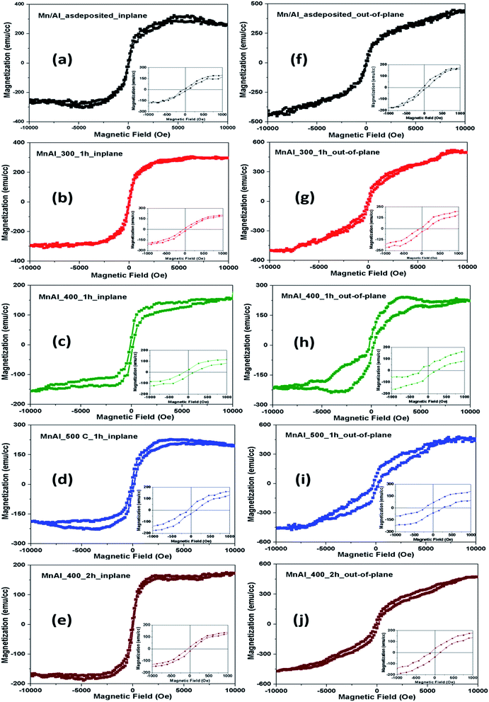 | ||
| Fig. 6 In-plane (a–e) and out-of-plane (f–j) magnetic hysteresis (M–H) loops measured at room temperature for the as-deposited bilayer and annealed MnAl thin films. | ||
| Thin film | In-plane | Out-of-plane | ||||
|---|---|---|---|---|---|---|
| Hc (Oe) | Ms (emu cm−3) | Mr/Ms | Hc (Oe) | Ms (emu cm−3) | Mr/Ms | |
| As-deposited | 57 | 270 | 0.078 | 57 | 440 | 0.036 |
| MnAl_300_1h | 55 | 300 | 0.073 | 95 | 500 | 0.052 |
| MnAl_400_1h | 128 | 160 | 0.17 | 175 | 230 | 0.19 |
| MnAl_500_1h | 130 | 200 | 0.16 | 244 | 465 | 0.14 |
| MnAl_400_2h | 70 | 176 | 0.10 | 127 | 480 | 0.08 |
The hysteresis loops of the as-deposited film indicated weak ferromagnetic nature with small coercivity as shown in Fig. 6(a) and (f). The in-plane M–H loop for the MnAl_300_1h film (Fig. 6(b)) showed a decrease in coercivity and a slight increase in magnetization, while the out-of-plane hysteresis (Fig. 6(g)) had a slight increase in coercivity and magnetization as compared to the as-deposited film (Table 3). The small coercivity observed in the as-deposited bilayer and MnAl_300_1h films could be attributed to the presence of a low fraction of ferromagnetic τ-phase, confirmed by XRD results (Fig. 2). As the annealing temperature increased to 400 °C, the ferromagnetic τ-phase was enhanced with the increase in coercivity and squareness, although the saturation magnetization decreased for the in-plane and out-of-plane magnetic hysteresis loops for the MnAl_400_1h sample. The increased coercivity in this film could be attributed to the smaller grain size, whereas the lower saturation magnetization was due to the greater roughness of the MnAl_400_1h film; similar behaviour was observed by other groups.37–39 It is known that the magnetization alignment process could change with the change in surface roughness,38 and the saturation magnetization decreased with increased roughness.39 The decrease in saturation magnetization with the increase in coercivity and squareness of the MnAl thin film after annealing was also reported in a previous study.40 Film MnAl_400_1h exhibited better ferromagnetic properties when a magnetic field was applied perpendicular to the film plane, indicating that the direction of the magnetic easy axis was perpendicular to the film plane. On further increasing the annealing temperature from 400 to 500 °C, the MnAl_500_1h film showed an increase in the coercivity and magnetization in both the in-plane and out-of-plane measurements (see Table 4), due to the enhancement of the ferromagnetic τ-phase as confirmed by the XRD results. The shape of the in-plane and out-of-plane hysteresis loop indicates that the direction of the easy axis was parallel to the MnAl_500_1h film plane. The out-of-plane hysteresis curve exhibited higher coercivity and magnetization as compared to the in-plane hysteresis loop for all samples.
| Film (Ta) | Hs (Oe) | Ms (emu cm−3) | Hk = Hs + 4πMs | Ku or Keff = MsHk/2 | Ku (erg cm−3) |
|---|---|---|---|---|---|
| MnAl_400_1h | 3200 | 150 | 5084 | 381![[thin space (1/6-em)]](https://www.rsc.org/images/entities/char_2009.gif) 300 300 |
3.8 × 10⁵ |
| MnAl_500_1h | 2500 | 200 | 5012 | 501![[thin space (1/6-em)]](https://www.rsc.org/images/entities/char_2009.gif) 200 200 |
5.0 × 10⁵ |
| MnAl_400_2h | 1800 | 200 | 4312 | 431![[thin space (1/6-em)]](https://www.rsc.org/images/entities/char_2009.gif) 200 200 |
4.3 × 10⁵ |
We observed that magnetic properties were enhanced in annealed MnAl films with the increase in annealing temperature from 300 to 500 °C. The increased coercivity can also be related to the decrease in grain size and enhancement of the τ-phase.7 Annealing at 400 °C enhanced the perpendicular magnetic anisotropy in the MnAl thin film, whereas the shapes of the out-of-plane hysteresis loops of other films (as-deposited and annealed) revealed that the easy axis was parallel to the plane of those films. The direction of the magnetic easy axis was changed after annealing the as-deposited film from 400 to 500 °C. This kind of switching of the direction of the easy axis due to different annealing temperatures was also observed in CoFe2O4 thin films by S. E. Shirsath and his group.30 It is clear from our results that the easy axis of the Mn/Al bilayer thin films can be tuned by changing the annealing temperatures.
Annealing time effects on the magnetic properties of samples MnAl_400_1h and MnAl_400_2h can be seen in Fig. 6(c and h) and (e and j), respectively. The magnetic hysteresis curves show the decrease in coercivity and increase in saturation magnetization of the in-plane and out-of-plane hysteresis of MnAl_400_2h film as compared to MnAl_400_1h film due to the enhancement of the ε-phase after annealing for a longer time. The increased magnetization of the MnAl_400_2h film could also be attributed to lower roughness.39 The XRD patterns shown in Fig. 3 also confirmed the enhancement of the ε-phase and reduction in the τ-phase on increasing the annealing time in the MnAl film. Our study revealed that increasing the annealing time might lead to the reduction of the ferromagnetic τ-phase, which is consistent with previous studies.14,27
The inset pictures in Fig. 6 show the hysteresis curves plotted at a lower scale. The uniaxial perpendicular magneto-crystalline anisotropy (PMA) constant (Ku or Keff) usually plays an important role in determining the HC of PMA materials. The saturation magnetization, Ms, and effective uniaxial anisotropy, Ku or Keff, were deduced from the hysteresis loops. By overlapping the hysteresis loops measured in two directions (in-plane and out-of-plane), the saturation field, Hs, was determined as the intercept of the two loops. As a result, the anisotropy field, Hk, was obtained as Hk = Hs + 4πMs, and the effective uniaxial anisotropy can be calculated by Keff = Hk × Ms/2.41,42 The values calculated from the parameters obtained from the in-plane and out-of-plane hysteresis curves are in the range 105 erg cm−3 and given in Table 4. These values are comparable to previously reported results.14
Magneto-optical characterization
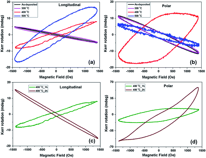
Magneto-optical Kerr effect (MOKE) measurements were performed by using linearly-polarized incident light, and the Kerr rotation angle of the material was recorded as a function of the applied magnetic field. MOKE results were consistent with the magnetic measurements performed using the VSM. The Kerr rotation angles were obtained in the longitudinal and the polar configurations at room temperature for as-deposited as well as for annealed films. The normal component of the magnetization was observed in the polar geometry, whereas the in-plane component was measured in the longitudinal geometry of MOKE. For the as-deposited and MnAl_300_1h films, the magnetic field induced longitudinal and polar Kerr rotation angle of the polarized light reflected from the surface of samples displayed tilted loops with negative Kerr rotation value. These tilted loops indicate the antiferromagnetic nature in the as-deposited and MnAl_300_1h films; similar tilted loops were also observed in FeMn films.43 The antiferromagnetic nature could be due to the presence of the ε-phase, which is dominant in these samples, as confirmed by XRD and VSM results. Films annealed at higher temperatures (400 and 500 °C) show non-rectangular in-plane ferromagnetic MOKE-hysteresis loops, which did not saturate, with a coercivity of 258 Oe and 557 Oe and maximum Kerr rotation of around 8 mdeg and 17 mdeg, respectively (see Fig. 7(a)). On the other hand, polar Kerr rotation showed nearly rectangular hysteric behaviours (with a coercivity of 929 Oe and maximum Kerr rotation of ∼11 mdeg) for the MnAl_400_1h film. It confirmed that the direction of the easy axis was perpendicular to the plane of the film (MnAl_400_1h), consistent with the VSM results. The normal component of the remanent magnetization vanished in the MnAl_500_1h film and the polar MOKE hysteresis loop was reduced to a tilted loop with negative Kerr rotation due to the presence of the antiferromagnetic ε-phase (see Fig. 7(b)). The reduction in normal component could be related to the magnetic anisotropy in this sample. The shapes of the out-of-plane magnetic hysteresis loops shown in Fig. 6(h) and (i) also indicate that the magnetic easy axis direction changed from perpendicular to parallel to the film plane on increasing the annealing temperature from 400 to 500 °C. The observed MOKE hysteresis loops clearly suggested that the MnAl_400_1h and MnAl_500_1h films were ferromagnetic at room temperature.Longitudinal and polar MOKE hysteresis of MnAl_400_1h and MnAl_400_2h films are shown in Fig. 7(c) and (d), respectively. The in-plane component of the remanent magnetization diminished and, due to the presence of the ε-phase, the MnAl_400_2h film exhibited a tilted loop. It has been confirmed from XRD results (Fig. 3) that the ε-phase was enhanced on increasing the annealing time, which exhibited antiferromagnetic nature.20,29 The polar Kerr rotation increased from 11 mdeg to 58 mdeg and polar coercivity decreased from 929 Oe to 434 Oe, after increasing the annealing time from one hour to two hours at 400 °C. The polar MOKE hysteresis of the MnAl_400_2h film exhibited an asymmetric shape and was shifted by a field of +217 Oe. The shifting of the MOKE loop along the applied magnetic field direction has been also observed in another study.44 The increase in the polar Kerr rotation could be due to the significant increase in the normal component of magnetization and anisotropy as observed from the magnetic hysteresis loop (Fig. 6), whereas the decrease in the polar coercivity and the asymmetric shape of the MOKE loop could be due to the enhancement of the ε-phase in the MnAl_400_2h film. The asymmetric shape of the polar MOKE loop is related to different reversal modes on both branches, like coherent rotation on one side and incoherent rotation or domain wall motion on the other side.44,45
The minor MOKE hysteresis loops were observed for all samples as the applied magnetic field (1500 Oe) was not enough to saturate the magnetization of the MnAl thin films. It has been reported in the literature that the MnAl thin film showed a high Kerr signal and was saturated for an applied magnetic field value of around 10 kOe.24,46 A large MOKE signal was observed in samples annealed at 400 and 500 °C, which is similar to another MOKE study on a manganese alloy (Mn3Sn single crystal).23 The ferromagnetic properties of the Mn/Al bilayer thin film were enhanced with the increase in the annealing temperature (400 and 500 °C) and can be seen from the longitudinal MOKE results, consistent with the VSM measurements. Also, the out-of-plane ferromagnetic properties were enhanced in the MnAl_400_1h film and diminished in the MnAl_500_1h film. The samples annealed at 400 °C showed higher coercivities and Kerr rotations when the magnetic field was applied perpendicular to the films, indicating that the easy axis is out of the plane of the films. The effects of annealing time on the magnetic and magneto-optic properties are also consistent. The in-plane magnetic hysteresis curve of the MnAl_400_2h film showed a significant decrease in coercivity and a small increase in magnetization as compared to the MnAl_400_1h film. The out-of-plane magnetic hysteresis loop of the MnAl_400_2h film showed a slight decrease in coercivity and a significant increase in magnetization as compared to the MnAl_400_1h film. Similarly, the MOKE results revealed a decrease in the in-plane component of the remanent magnetization and an increase in the polar Kerr rotation with decreased coercivity on increasing annealing time. Increasing the annealing temperature enhanced the τ-phase and reduced the ε-phase in MnAl thin films annealed for one hour. Annealing for longer times enhanced ε-phase and reduced the τ-phase in MnAl_400_2h thin film as compared to MnAl_400_1h. Our MOKE study confirmed that for the MnAl_400_1h and MnAl_400_2h films, the easy axis was perpendicular to the plane of the respective film, whereas the MnAl_500_1h film exhibited an easy axis along the direction of the plane of the film.
Conclusions
In conclusion, we have investigated the effects of annealing temperature and time on the structural, magnetic and magneto-optical properties of Mn/Al bilayer thin films deposited on GaAs substrates by the evaporation technique. The as-deposited Mn/Al bilayer thin films were annealed at different temperatures in the range 300–500 °C. The ferromagnetic τ-phase was enriched after annealing the as-deposited film ≥400 °C, which was confirmed by XRD, magnetic hysteresis loops, as well as MOKE measurements. The AFM micrographs revealed that the surface roughness first increased on annealing the as-deposited film up to 400 °C, due to the strong diffusion of Mn and Al atoms, and then decreased with further increase in the annealing temperature and time because of the smoothening of the films. The MnAl_400_1h film showed rectangular magnetic hysteresis loops (both, in-plane and out-of-plane), with higher saturation magnetization and coercivity in the direction perpendicular to the film plane. The polar MOKE hysteresis of the same film also showed better properties as compared to longitudinal MOKE hysteresis, indicating that the direction of the magnetic easy axis was perpendicular to the film plane. For the MnAl_500_1h film, both the VSM and MOKE results confirmed that the easy axis direction was parallel to the plane of the film. Our study in the annealing time effects revealed that MnAl film annealed at 400 °C for one hour showed better ferromagnetic properties than film annealed for two hours. Therefore, this study suggests that the magnetic easy axis (anisotropy) of MnAl thin films can be controlled by selecting the appropriate annealing temperature, which could be useful for magnetic devices and magneto-optical recording media.Conflicts of interest
There are no conflicts to declare.Acknowledgements
The authors are grateful to Director CSIR-NPL, Delhi for his encouragement. Authors are also thankful to Dr S. A. Khan and Target lab members of IUAC, New Delhi for their cooperation in carrying out some of the experimental work. H. Khanduri acknowledges the Department of Science and Technology, New Delhi, India, for DST-INSPIRE Faculty Grant (IFA17-MS130).References
- T. S. Chin, J. Magn. Magn. Mater., 2000, 209, 75 CrossRef CAS.
- J. D. Boeck, W. V. Roy, V. Motsnyi, V. Motsnyi, Z. Liu, K. Dessein and G. Borghs, Thin Solid Films, 2002, 412, 3 CrossRef.
- J. M. D. Coey, J. Phys.: Condens. Matter, 2014, 26, 064211 CrossRef CAS PubMed.
- S. Zhao, Y. Wu, C. Zhang, J. Wang, Z. Fu, R. Zhang and C. Jiang, J. Alloys Compd., 2018, 755, 257–264 CrossRef CAS.
- C. Y. Duan, X. P. Qiu, B. Ma, Z. Z. Zhang and Q. Y. Jin, Mater. Sci. Eng. B, 2009, 162, 185–188 CrossRef CAS.
- J. J. Van Den Broek, H. Donkersloot, G. Van Tendeloo and J. Van Landuyt, Acta Mater., 1979, 27, 1497 CrossRef CAS.
- Q. Zeng, I. Baker, J. B. Cui and Z. C. Yan, J. Magn. Magn. Mater., 2007, 308, 214–226 CrossRef CAS.
- C. Yanar, J. M. K. Wiezorek, V. Radmilovic and W. A. Soffa, Metall. Mater. Trans. A, 2002, 33, 2413 CrossRef.
- D. P. Hoydick, E. J. Palmiere and W. A. Soffa, J. Appl. Phys., 1997, 81, 5624 CrossRef CAS.
- F. Jiménez-Villacorta, J. L. Marion, T. Sepehrifar, M. Daniil, M. A. Willard and L. H. Lewis, Appl. Phys. Lett., 2012, 100, 112408 CrossRef.
- H. Saruyama, M. Oogane, Y. Kurimoto, H. Naganuma and Y. Ando, Jpn. J. Appl. Phys., Part 1, 2013, 52(6R), 063003 CrossRef.
- H. Kono, J. Phys. Soc. Jpn., 1958, 13(12), 1444–1451 CrossRef CAS.
- W. Van Roy, J. De Boeck, H. Bender, C. Bruynseraede, A. Vanesch and G. Borghs, J. Appl. Physiol., 1995, 78, 398 CrossRef CAS.
- S. Zhao, T. Hozumi, P. LeClair, G. Mankey and T. Suzuki, IEEE Trans. Magn., 2015, 51(11), 1–4 CAS.
- S. H. Nie, L. J. Zhu, J. Lu, D. Pan, H. L. Wang, X. Z. Yu, J. X. Xiao and J. H. Zhao, Appl. Phys. Lett., 2013, 102, 152405 CrossRef.
- C. Navio, M. Villanueva, E. Cespedes, F. Mompean, M. Garcıa-Hernandez, J. Camarero and A. Bollero, APL Mater., 2018, 6, 101109 CrossRef.
- J. Harbison, T. Sands, R. Ramesh, L. Florez, B. Wilkens and V. Keramidas, J. Cryst. Growth, 1991, 111(1), 978–983 CrossRef CAS.
- R. L. Stamps, S. Breitkreutz, J. Åkerman, A. V. Chumak, Y. Otani, G. E. Bauer, J.-U. Thiele, M. Bowen, S. A. Majetich, M. Klaui, I. L. Pre- jbeanu, B. Dieny, N. M. Dempsey and B. Hillebrands, J. Phys. D: Appl. Phys., 2014, 47(33), 333001 CrossRef.
- T. Sands, J. Harbison, M. Leadbeater, S. Allen Jr, G. Hull, R. Ramesh and V. Keramidas, Appl. Phys. Lett., 1990, 57(24), 2609–2611 CrossRef CAS.
- H. Khanduri, S. Khan, S. Srivastava, I. Sulania, M. Chandra, J. Link, R. Stern and D. Avasthi, Mater. Res. Express, 2019, 6, 056405 CrossRef CAS.
- T. Haider, Int. J. Electromagn. Appl., 2017, 7(1), 17–24 Search PubMed.
- E. du Tremolet de Lacheisserie, Magnétisme T. 1, EDP Sciences, 2000, p. 401 Search PubMed.
- T. Higo, H. Man, D. B. Gopman, L. Wu, T. Koretsune, O. M. J. van't Erve, Y. P. Kabanov, D. Rees, Y. Li, M.-T. Suzuki, S. Patankar, M. Ikhlas, C. L. Chien, R. Arita, R. D. Shull, J. Orenstein and S. Nakatsuji, Nat. Photonics, 2018, 12, 73–78 CrossRef CAS PubMed.
- L. Zhu, L. Brandt and J. Zhao, J. Phys. D: Appl. Phys., 2016, 49, 41500 Search PubMed.
- J. Cui, M. Kramer, L. Zhou, F. Liu, A. Gabay, G. Hadjipanayis and D. Sellmyer, Acta Mater., 2018, 158, 118–137 CrossRef CAS , https://www.sciencedirect.com/science/article/pii/S1359645418305858.
- Z. Liu, K. Su, Y. Cheng and R. V. Ramanujan, Mater. Sci. Eng. Adv. Res., 2015, 1(1), 12–19 CrossRef.
- S. Sato and S. Irie, AIP Adv., 2019, 9, 035015 CrossRef.
- C. Y. Duan, X. P. Qiu, B. Ma, Z. Z. Zhang and Q. Y. Jin, Mater. Sci. Eng. B, 2009, 162, 185–188 CrossRef CAS.
- F. Jiménez-Villacorta, J. L. Marion, J. T. Oldham, M. Daniil, M. A. Willard and L. H. Lewis, Metals, 2014, 4, 8–19 CrossRef.
- S. E. Shirsath, X. Liu, Y. Yasukawa, S. Li and A. Morisako, Sci. Rep., 2016, 6, 30074 CrossRef CAS PubMed.
- X. Li, Y.-C. Chang, J.-Y. Chen, K.-W. Lin, R. D. Desautels, J. van Lierop and P. W. T. Pong, Phys. Lett. A, 2018, 382, 2886–2893 CrossRef CAS.
- Z. S. Khalifa, RSC Adv., 2017, 7, 30295–30302 RSC.
- W. Li, C. Ni, H. Lin, C. P. Huang and S. Ismat Shah, J. Appl. Phys., 2004, 96, 6663 CrossRef CAS.
- S. Masudy-Panah, R. S. Moakhar, C. S. Chua, A. Kushwaha, T. I. Wong and G. K. Dalapati, RSC Adv., 2016, 6, 29383–29390 RSC.
- H. Khanduri, M. Chandra Dimri, S. Vasala, S. Leinberg, R. Lõhmus, T. V. Ashworth, A. Mere, J. Krustok, M. Karppinen and R. Stern, J. Phys. D: Appl. Phys., 2013, 46, 175003 CrossRef.
- S. Bance, F. Bittner, T. G. Woodcock, L. Schultz and T. Schrefl, Acta Mater., 2017, 131, 48–56 CrossRef CAS.
- K. Koike, T. Kusano, D. Ogawa, K. Kobayashi, H. Kato, M. Oogane, T. Miyazaki, Y. Ando and M. Itakura, Nanoscale Res. Lett., 2016, 11, 33 CrossRef PubMed.
- S. Iwatsubo, T. Takahashi and M. Nao, Thin Solid Films, 1999, 343–344, 67–70 CrossRef CAS.
- Y. P. Zhao, R. M. Gamache, G.-C. Wang, T.-M. Lu, G. Palasantzas and J. Th. M. De Hosson, J. Appl. Phys., 2001, 89, 1325 CrossRef CAS.
- E. Y. Huang and M. H. Kryder, J. Appl. Phys., 2015, 117, 17E314 CrossRef.
- D. T. Ngo, Z. L. Meng, T. Tahmasebi, X. Yu, E. Thoeng, L. H. Yeo, A. Rusydi, G. C Han and K.-L. Teo, J. Magn. Magn. Mater., 2014, 350, 42 CrossRef CAS.
- S. Fukami, T. Suzuki, Y. Nakatani, N. Ishiwata, M. Yamanouchi, S. Ikeda, N. Kasai and H. Ohno, Appl. Phys. Lett., 2011, 98, 082504 CrossRef.
- Y. Hwang, S. Choi, J. Choi and S. Cho, Sci. Rep., 2019, 9, 3669 CrossRef PubMed.
- K. Schlage, R. Röhlsberger, T. Klein, E. Burke, C. Strohm and R. Rüffer, New J. Phys., 2009, 11, 013043 CrossRef.
- J. McCord, R. Schäfer, R. Mattheis and K. U. Barholz, J. Appl. Phys., 2003, 93, 5491 CrossRef CAS.
- N. Anuniwat, Y. Cui, S. A. Wolf, J. Lu and B. D. Weaver, Appl. Phys. Lett., 2013, 102, 102406 CrossRef.
| This journal is © The Royal Society of Chemistry 2019 |

