 Open Access Article
g-C3N4/CuO and g-C3N4/Co3O4 nanohybrid structures as efficient electrode materials in symmetric supercapacitors
Jithesh Kavila,
P. M. Anjanabc,
Deepak Joshya,
Ameya Babua,
Govind Rajd,
P. Periyat*a and
R. B. Rakhi *bc
*bc
aDepartment of Chemistry, University of Calicut, Kerala, India-673635. E-mail: pperiyat@uoc.ac.in
bChemical Sciences and Technology Division, CSIR-National Institute of Interdisciplinary Sciences (CSIR-NIIST), Thiruvananthapuram, Kerala, India 695019. E-mail: rakhi.raghavanbaby@niist.res.in
cDepartment of Physics, University of Kerala, Thiruvananthapuram, Kerala, India 695019. E-mail: rbrakhi@keralauniversity.ac.in
dDepartment of Chemistry, Malabar Christian College, Calicut, Kerala, India-673635
First published on 25th November 2019
Abstract
Metal oxide dispersed graphitic carbon nitride hybrid nanocomposites (g-C3N4/CuO and g-C3N4/Co3O4) were prepared via a direct precipitation method. The materials were used as an electrode material in symmetric supercapacitors. The g-C3N4/Co3O4 electrode based device exhibited a specific capacitance of 201 F g−1 which is substantially higher than those using g-C3N4/CuO (95 F g−1) and bare g-C3N4 electrodes (72 F g−1). At a constant power density of 1 kW kg−1, the energy density given by g-C3N4/Co3O4 and g-C3N4/CuO devices is 27.9 W h kg−1 and 13.2 W h kg−1 respectively. The enhancement of the electrochemical performance in the hybrid material is attributed to the pseudo capacitive nature of the metal oxide nanoparticles incorporated in the g-C3N4 matrix.
Introduction
Renewable energy storage and its supply upon demand have been a major challenge for researchers owing to the short life span and poor power delivery of conventionally used lithium-ion batteries.1 The supercapacitor has been recognized as a suitable storage device that can be used in combination with batteries to mitigate the power delivery problems associated with batteries.2,3 Supercapacitors possess excellent performance recyclability due to the absence of any mass transfer between the electrodes.4 Carbon-based electrode materials have been used conventionally in supercapacitors owing to their high surface area and storage capacity.5,6 Nitrogen-doped carbon allotropes emerged recently as supercapacitor electrodes, which show excellent electrode electrolyte interaction due to the presence of lone pair electrons on the nitrogen atom.7Graphitic carbon nitride (g-C3N4) is considered as an intrinsically nitrogen-rich system with lamellar structure. It is the most stable allotrope of carbon nitrides at ambient atmosphere, but it also has rich surface properties that are attractive for many applications including supercapacitor electrode and hydrogen evolution photocatalyst.8 The polymeric structure of g-C3N4 arises from the repetition of tri-s-triazine (symm. 1,3,5 triazine) units and the 2D lamellar structure arises from the weak van der-Waals interaction between the layers. The lone pair of electron on nitrogen could provide surface polarity on the electrode material and that could offer several binding sites for the electrolyte ions to interact with the electrode surface.9 However, the semiconducting nature, low surface area and the agglomerated layer structure limit its application as a supercapacitor electrode.10
As in other carbon electrodes, the charge storage in g-C3N4 is due the formation of electrical double layer at the electrode–electrolyte interface (EDLC) which is non-faradaic in nature. However the pseudo capacitive behavior in transition metal oxides (TMO), sulphides and conducting polymers arises due to the fast and reversible redox process between the electroactive material and electrolyte molecule (faradaic process).11–15 Thus TMO with pseudocapacitive nature can be suitably coupled with g-C3N4 layer structure to mitigate the limitations of bare g-C3N4 electrodes.16
The commonly used transition metal oxides are ruthenium oxide,17 manganese dioxide,18 tungsten oxide,19 nickel oxide,20 etc. Among them, Co3O4 and CuO have received a great deal of attention due to their economically viable and environmentally friendly nature.21,22 Moreover, as reported by Zhou et al. Co3O4 shows a very high theoretical capacitance of 3560 F g−1 with an excellent shuttling between its Co2+ and Co3+ ions during electrochemical process.23,24 In a recent report by Zheng et al. mesoporous Co3O4 was anchored on the g-C3N4 surface, and the composite material showed a specific capacitance value of 780 F g−1 at a current density of 1.25 A g−1.25 In another attempt, Shim et al. fabricated a supercapacitor from carbon and CuO anchored g-C3N4, which has given a specific capacitance value of 247.2 F g−1 at a current density of 1 A g−1.26 In the available reports, the electrochemical measurements were carried out in three electrode configuration. However, the actual performance of the device should be tested in two electrode configuration for practical applications. Only a very few reports are available in the literature based on the electrochemical properties of g-C3N4 and Co3O4, CuO nanohybrid systems.
In the present work pseudocapacitive Co3O4 and CuO metal oxides were grown on the surface of a 2D g-C3N4 phase. The hybrid materials were employed as electrode material in symmetric supercapacitors. The highlight of the present research is that the electrochemical properties of Co3O4 and CuO modified g-C3N4 were analyzed for the first time in symmetric two electrode configuration. The present research will be an excellent reference for the researchers working in the area of developing high energy density electrode materials with environmentally and economically benign nature.
Experimental
Synthesis of g-C3N4
g-C3N4 layer structure was prepared by the method reported elsewhere.4 In a typical method, 5 g of thiourea was taken in a tightly closed silica crucible. The sample was heated to a temperature of 550 °C for 4 hours at a heating rate of two degrees per minute. The yellow colored g-C3N4 phase was formed inside the crucible due to high-temperature self-polymerization of thiourea.Synthesis of g-C3N4/CuO and g-C3N4/Co3O4 hybrid nanocomposites
Transition metal oxide (TMO) anchored g-C3N4 such as g-C3N4/Co3O4, g-C3N4/CuO hybrid nanocomposites, with g-C3N4![[thin space (1/6-em)]](https://www.rsc.org/images/entities/char_2009.gif) :
:![[thin space (1/6-em)]](https://www.rsc.org/images/entities/char_2009.gif) TMO weight ratio of 7
TMO weight ratio of 7![[thin space (1/6-em)]](https://www.rsc.org/images/entities/char_2009.gif) :
:![[thin space (1/6-em)]](https://www.rsc.org/images/entities/char_2009.gif) 3 was prepared by a simple precipitation technique. In this method, 0.06 g g-C3N4 was weighed out separately in two beakers and dispersed in 50 ml distilled water by ultrasonication. 0.045 g CuNO3 and 0.06 g CoNO3 were dissolved separately and mixed with g-C3N4 suspension by sonication for another 30 minutes. NH4OH solution was added carefully to the suspension, and the pH was adjusted to 9. The precipitate of metal hydroxides so obtained was washed several times with de-ionised water, dried and calcined at a temperature of 300 °C for 2 h.
3 was prepared by a simple precipitation technique. In this method, 0.06 g g-C3N4 was weighed out separately in two beakers and dispersed in 50 ml distilled water by ultrasonication. 0.045 g CuNO3 and 0.06 g CoNO3 were dissolved separately and mixed with g-C3N4 suspension by sonication for another 30 minutes. NH4OH solution was added carefully to the suspension, and the pH was adjusted to 9. The precipitate of metal hydroxides so obtained was washed several times with de-ionised water, dried and calcined at a temperature of 300 °C for 2 h.
General characterizations
The crystalline structure and phase formations of the materials were characterized by Bruker X-ray diffractometer using Copper Kα radiation (λ = 0.1546 nm). Infrared spectra of the samples were recorded from Jasco-FT/IR-4100 spectrometer. X-ray photoelectron spectroscopy (XPS) analysis was carried out from Ultra Axis Kratos Analytical, UK, XPS instrument with an Al Kα X-ray source. The morphologies of the samples were characterized using field emission scanning electron microscope, Carl-Zeiss Gemini-300. Electrochemical studies of the samples were performed using VMP3 Biologic electrochemical workstation.Preparation of electrode and electrochemical analysis
The electrode preparation procedure for the fabrication of symmetric supercapacitor was given as follows. In a typical method 8![[thin space (1/6-em)]](https://www.rsc.org/images/entities/char_2009.gif) :
:![[thin space (1/6-em)]](https://www.rsc.org/images/entities/char_2009.gif) 1
1![[thin space (1/6-em)]](https://www.rsc.org/images/entities/char_2009.gif) :
:![[thin space (1/6-em)]](https://www.rsc.org/images/entities/char_2009.gif) 1 ratio of the active material, PTFE binder, and the conducting material was mixed with ethanol and ultrasonicated for 30 minutes to obtain a uniform slurry. It was then coated uniformly on two conducting carbon cloth (ELAT, NuVant Systems Inc.) substrate having 2 × 2 cm dimension and dried in a vacuum oven at 100 °C for 6 hours. The electrodes were then sandwiched on a separator (Celgard 3400), which was wetted with 30% KOH solution and placed carefully in an electrochemical test cell (ECC-std, EL-Cell GmbH).27 The electrochemical measurements of the assembled device were performed in symmetric two electrode configuration by using cyclic voltammetry (CV), galvanostatic charge–discharge (GCD) and electrochemical impedance spectroscopy (EIS) by attaching the leads of the test cell to the electrochemical workstation (VMP3 Biologic).
1 ratio of the active material, PTFE binder, and the conducting material was mixed with ethanol and ultrasonicated for 30 minutes to obtain a uniform slurry. It was then coated uniformly on two conducting carbon cloth (ELAT, NuVant Systems Inc.) substrate having 2 × 2 cm dimension and dried in a vacuum oven at 100 °C for 6 hours. The electrodes were then sandwiched on a separator (Celgard 3400), which was wetted with 30% KOH solution and placed carefully in an electrochemical test cell (ECC-std, EL-Cell GmbH).27 The electrochemical measurements of the assembled device were performed in symmetric two electrode configuration by using cyclic voltammetry (CV), galvanostatic charge–discharge (GCD) and electrochemical impedance spectroscopy (EIS) by attaching the leads of the test cell to the electrochemical workstation (VMP3 Biologic).
Results and discussions
X-ray diffraction
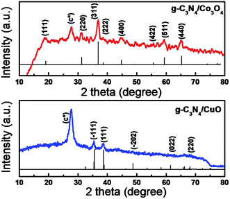
The X-ray diffraction studies of the composite samples were carried out to analyze the phase formation of the component phases and were given as Fig. 1, the JCPDS card file is included along with XRD data for better understanding. In the XRD spectrum of g-C3N4/Co3O4 (Fig. 1(a)), the peaks at 2θ values 18.9, 31.2, 36.9, 38.2, 44.7, 54.8, 59.4 and 65.3 corresponds to the diffraction from (111), (220), (311), (222), (400), (422), (511) and (440) planes of cubic phase of Co3O4 (JCPDS no: 43-1003). The XRD spectrum of g-C3N4/CuO shows reflections at 2θ values 35.6, 38.5, 49.2, 66.6 and 68.2 corresponds to (−111), (111), (−202), (022) and (220) planes of the monoclinic phase of CuO (JCPDS no: 00-001-1117). The crystallite size of the particles calculated from Debye–Scherrer formula was 8–10 nm and 10–15 nm for g-C3N4/CuO and g-C3N4/Co3O4 respectively. The diffraction peaks marked as (C*) is the characteristic peak of g-C3N4 originated from the layer stacking arrangements in two-dimensional g-C3N4 networks.FTIR spectra
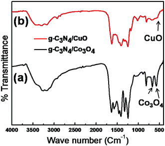
FTIR analysis (Fig. 2) of the composite sample was done to analyze the phase formation of the constituent phases further and to determine the presence of a functional group attached to the surface of the electrode material. The common peaks in both the spectra of g-C3N4/Co3O4 and g-C3N4/CuO are due to the contribution from the g-C3N4 phase. The peaks at the region of 1200–1600 cm−1 arise from the –CN stretching vibrations of the heterocyclic rings of s-triazine units. The sharp at 810 cm−1 is the characteristic peak originating from the breathing mode vibrations of triazine ring.28 The peaks around 1000–1100 cm−1 arise due to the bending vibrations of –OH functional groups and the broad peaks around 3200–3600 cm−1 originate from the stretching vibrations of H2O molecules adsorbed on the surface of the electrode material. The existence of spinel Co3O4 nanoparticles on the electrode sample can be confirmed from the presence of sharp characteristic peaks in Fig. 2(a) at 575 cm−1 and 665 cm−1, respectively.12 The peak at 537 cm−1 in Fig. 2(b) is the stretching vibrational band of Cu–O bond in monoclinic CuO crystal.22X-ray photoelectron spectroscopy (XPS)
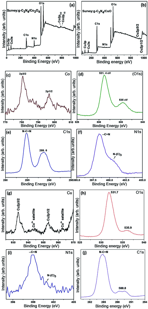
XPS spectra of the hybrid nanostructures g-C3N4/Co3O4 and g-C3N4/CuO were recorded in order to analyze the chemical composition and the electronic environment of the electrode materials. The survey XPS spectra of the samples were given as Fig. 3(a) and (b). The survey spectrum confirms the presence of constituent phases in the composite sample. Binding energy values in all the spectra were carbon corrected by comparing with C 1s value of 284.8 eV. The high resolution XPS spectra of Co in Fig. 3(c) exhibit well defined peaks at 780 and 796 eV corresponding to the Co 2p3/2 and Co 2p1/2 spin states with a spin separation of 16 eV, which are the characteristics of Co3O4 phase. Two weak satellite peaks at 788 and 804 eV are the features of spinel structure in which +3 ion occupy octahedral site and +2 ion at the tetrahedral sites.29 The O 1s peak at 531.2 eV in Fig. 3(d) is the characteristic peak of spinel Co3O4 structure which arises due to the presence of lattice oxygen. Second O 1s peak at 535.9 eV is due to the presence of defective oxygen on the surface of the Co3O4 phase. The two major peaks of C 1s in Fig. 3(e) at 284.8 and 288.6 eV are originated from the sp2 hybridised N–C![[double bond, length as m-dash]](https://www.rsc.org/images/entities/char_e001.gif) N structure of g-C3N4 network. The N 1s peaks in Fig. 3(f) at 398.4 and 400.5 eV are attributed to the N atom from N–C
N structure of g-C3N4 network. The N 1s peaks in Fig. 3(f) at 398.4 and 400.5 eV are attributed to the N atom from N–C![[double bond, length as m-dash]](https://www.rsc.org/images/entities/char_e001.gif) N and N–(C)3 structural units of g-C3N44.
N and N–(C)3 structural units of g-C3N44.
The high resolution XPS spectra of Cu in g-C3N4/CuO is depicted in Fig. 3(g). The peaks at 933.2 and 953.3 eV are the characteristic signal of Cu 2p3/2 and Cu 2p1/2 respectively and the satellite peaks of Cu2+ at higher binding energy region are also visible.29 The O 1s give spectra at 531.4 and 536.1 eV which is the characteristics of lattice and defective oxygen respectively (Fig. 3(h)). C 1s peaks at (Fig. 3(i)) 284.7 eV, 288.8 eV and the N 1s peaks (Fig. 3(j)) 398.9 eV and 400.9 eV are the characteristic peaks of g-C3N4 as discussed in the case of g-C3N4/Co3O4.4
Morphology analysis
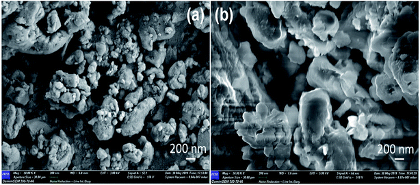
The surface morphology of the composite electrodes g-C3N4/Co3O4 and g-C3N4/CuO were depicted as Fig. 4(a) and (b). g-C3N4/Co3O4 sample exhibited a spherical morphology with porous nature, however in g-C3N4/CuO the particles aggregated together to form large grains which is unfavorable for the penetration of electrolyte molecules during electrochemical process. The crystalline nature of the materials were further analysed using TEM. As can be seen from Fig. 5(a) the Co3O4 particles were uniformly distributed in the network of g-C3N4 with a clear boundary between the constituent phases; however, in the case of g-C3N4/CuO (Fig. 5(c)), the distribution of CuO in g-C3N4 matrix is non-homogeneous with a small aggregation of metal oxide phases in the matrix. The SAED patterns of the composite sample indicated that in g-C3N4/CuO (Fig. 5(d)), the metal oxide phases are more crystalline with bright spots than in g-C3N4/Co3O4 (Fig. 5(b)). The crystalline phases usually reduce the performance of an electrochemical device by decreasing the accessible surfaces for the electrolyte molecule to interact with the electrode surface. It is also seen from SAED pattern that the diffraction patterns are obtained from the highly populated planes of Co3O4 (311) and CuO (111) & (−111) in the composite material.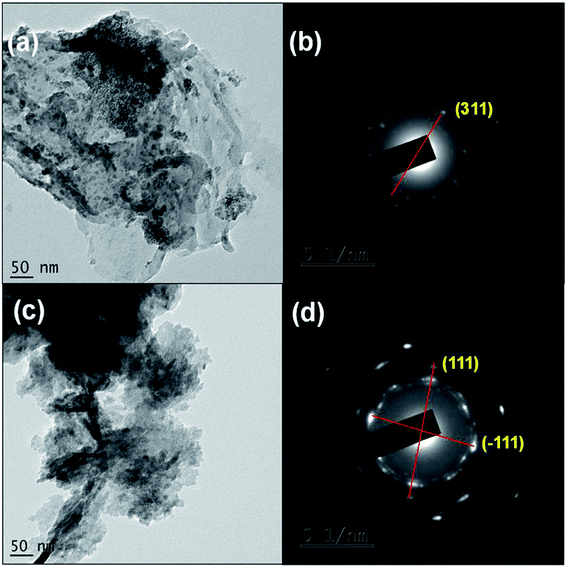 | ||
| Fig. 5 (a) and (c) TEM images of g-C3N4/Co3O4 and g-C3N4/CuO; (b) and (d) corresponding SAED patterns. | ||
Cyclic voltammogram (CV)
The CV profiles of g-C3N4/Co3O4and g-C3N4/CuO electrodes are shown in Fig. 6(a) and (b) respectively. The CV curve of an ideal supercapacitor material is expected to have a rectangular shape. In current (i)–voltage (v) curve, the value of current [i = C(v/t)] should be constant since the scan rate ‘(v/t)’ and capacitance ‘C’ are constant.18 In Fig. 6(a), the CV profiles of g-C3N4/Co3O4 electrodes show a nearly rectangular type CV and an excellent current response, which are the characteristic features of an ideal capacitor. The CV profile of the symmetric supercapacitor based on g-C3N4/CuO electrodes Fig. 6(b) shows a small deviation from ideal capacitive behavior as compared to the g-C3N4/Co3O4 electrode. The calculated value of specific capacitance (Csp) from CV profile for g-C3N4/CuO and g-C3N4/Co3O4 at a scan rate of 5 mV s−1 was found to be 238 F g−1 and 108 F g−1 respectively which is far greater than the Csp of bare g-C3N4 (74 F g−1). The variation in specific capacitance was compared in Fig. 6(c) with the scan rate for both the electrodes, with the electrochemical properties of bare g-C3N4. The Csp value of all the electrodes was high at lower scan rate since the electrolyte molecule get more time for their interaction with the electrode surface. Compared to the electrochemical performance of bare g-C3N4, the composite samples, g-C3N4/CuO and g-C3N4/Co3O4 have shown excellent performance due to the pseudocapacitive contribution from CuO and Co3O4 nanocrystals.21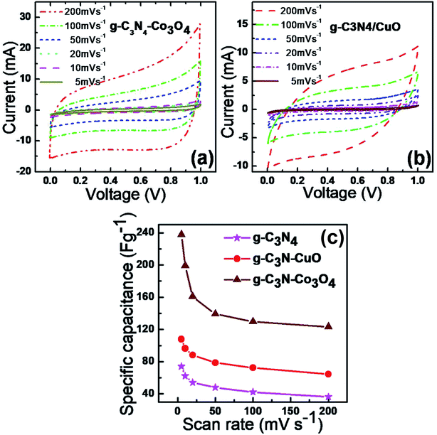 | ||
| Fig. 6 Cyclic voltammograms of (a) g-C3N4/Co3O4 and (b) g-C3N4/CuO at different scan rates. (c) Variation of specific capacitance of g-C3N4, g-C3N4/CuO and g-C3N4/Co3O4 with scan rate. | ||
Galvanostatic charge–discharge (GCD)
The actual device performance of the supercapacitor can be analyzed from the GCD experiments.30 The GCD profile was performed in 1 M KOH solution at different current densities of 1, 2, 3, 4, and 5 A g−1 and is shown in Fig. 7. Compared to g-C3N4/CuO (Fig. 7(b)); g-C3N4/Co3O4 (Fig. 7(a)) supercapacitor electrodes exhibited an almost rectangular type GCD curve indicating an excellent efficiency for the charge–discharge process. The IR drop at the beginning of the GCD curve indicates the internal resistance of the electrode materials arising from electrical contact resistance, bulk solution resistance, and resistance from ion migration. Compared to g-C3N4/CuO, the IR drop value of g-C3N4/Co3O4 is significantly lower, which indicates excellent charge efficiency for g-C3N4/Co3O4 supercapacitor. The specific capacitance value of the devices were calculated from the GCD profiles using the equation, ; where I is the discharge current, m is the mass loading of active material in a single electrode, Δt is the discharge time, and Δv is the cell potential range after IR drop. The Csp value of g-C3N4/CuO and g-C3N4/Co3O4 electrodes at a current density of 1 A g−1 was found to be 95 F g−1 and 201 F g−1, respectively. At high current densities, the Csp value of the devices decreases due to the limited interaction of the ions at the electrode–electrolyte interface.31
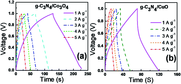 | ||
| Fig. 7 GCD curves of (a) g-C3N4/Co3O4 and (b) g-C3N4/CuO based supercapacitors at a constant current density of 1 A g−1 in 2 M KOH electrolyte. | ||
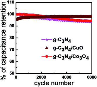
The cyclic stabilities of the supercapacitors were analyzed from the charge–discharge measurements under an applied current density of 5 A g−1 for 6000 cycles and given as Fig. 8. The g-C3N4/Co3O4 based device exhibited excellent cyclic stability of 97% even after 6000 cycles. However, the stability of g-C3N4/CuO and g-C3N4 based supercapacitors was found to be, 94% and 93% respectively. The agglomeration of the electrode material during the electrochemical process could be a reason for the reduced cyclic stability in g-C3N4/CuO and g-C3N4 electrodes.
The energy density and power density values of the devices were calculated from the GCD profile by the relation; E = ½CspV2 and P = E/Δt. At a constant power density of 1 kW kg−1, the energy densities possessed by g-C3N4/Co3O4 and g-C3N4/CuO based devices are 27.9 W h kg−1 and 13.2 W h kg−1 respectively.
Electrochemical impedance spectra (EIS)
EIS measurements were carried out to further analyze the performance of the devices (Fig. 9). The EIS spectra or the Nyquist plots consist of a semicircle at the high-frequency area and a vertical line at the low-frequency area. The radius of the semicircle (Rct) gives the value of charge transport resistance of the electrode material. A small arc radius in EIS spectra indicates a better charge transport at the electrode–electrolyte interface.32 EIS results show that the Rct value of g-C3N4/Co3O4 (Fig. 9(a)) is very small compared to g-C3N4/CuO (Fig. 9(b)) electrodes indicating an excellent charge transport in the g-C3N4/Co3O4 electrode. The low-frequency region of the impedance spectra is associated with the ionic diffusion from the bulk of the solution towards the electrode surface. A vertical line parallel to the y-axis of the plot is the ideal condition for a supercapacitor material. It can be seen that for g-C3N4/Co3O4 electrodes, the straight line at the low-frequency region is more vertical than the other electrode. Moreover, the length of the straight line is very small (less imaginary part) in g-C3N4/Co3O4 electrodes designating a lower resistance for ion diffusion from the bulk of the solution.33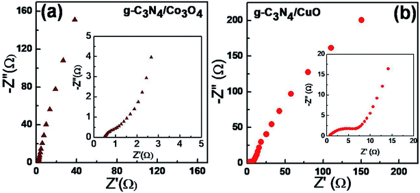 | ||
| Fig. 9 Nyquist plots for (a) g-C3N4/Co3O4 and (b) g-C3N4/CuO based supercapacitors over the frequency range from 100 kHz and 1 MHz. | ||
Conclusions
In summary, pseudocapacitive Co3O4 and CuO nano structures were anchored on the surface of the two dimensional g-C3N4 by direct precipitation method. The hybrid materials, g-C3N4/Co3O4 and g-C3N4/CuO were used as electrode materials in symmetric supercapacitors. The electrochemical performance of g-C3N4 exhibited significant enhancement by coupling with Co3O4 and CuO with a specific capacitance of 201 F g−1 and 95 F g−1 for g-C3N4/Co3O4 and g-C3N4/CuO composite materials respectively. The enhancement in electrochemical properties in the composites can be attributed to the presence of pseudocapacitive metal oxide phases. The g-C3N4/Co3O4 exhibited a cycling stability of 97% even after 6000 cycles with an energy density of 27.9 W h kg−1.Conflicts of interest
There are no conflicts to declare.Acknowledgements
R. B. Rakhi acknowledges the financial support from Ramanujan Fellowship (SB/S2/RJN-098/2015) from DST-SERB, Government of India. Jithesh Kavil is grateful to University Grants Commission, Govt. of India for FDP fellowship.References
- M. R. Palacín and A. de Guibert, Science, 2016, 351, 1253292 CrossRef PubMed.
- M. D. Stoller and R. S. Ruoff, Energy Environ. Sci., 2010, 3, 1294–1301 RSC.
- D. Guo, L. Lai, A. Cao, H. Liu, S. Dou and J. Ma, RSC Adv., 2015, 5, 55856–55869 RSC.
- J. Kavil, P. Anjana, C. Roshni, P. Periyat, K. G. Raj and R. Rakhi, Appl. Surf. Sci., 2019, 487, 109–115 CrossRef CAS.
- L. L. Zhang and X. Zhao, Chem. Soc. Rev., 2009, 38, 2520–2531 RSC.
- C. Huang, Y. Ding, C. Hao, S. Zhou, X. Wang, H. Gao, L. Zhu and J. Wu, Chem. Eng. J., 2019, 378, 122202 CrossRef CAS.
- L.-F. Chen, X.-D. Zhang, H.-W. Liang, M. Kong, Q.-F. Guan, P. Chen, Z.-Y. Wu and S.-H. Yu, ACS Nano, 2012, 6, 7092–7102 CrossRef CAS PubMed.
- S. P. Vattikuti, A. K. R. Police, J. Shim and C. Byon, Appl. Surf. Sci., 2018, 447, 740–756 CrossRef CAS.
- Y. Gong, M. Li and Y. Wang, ChemSusChem, 2015, 8, 931–946 CrossRef CAS PubMed.
- J. Kavil, P. Anjana, P. Periyat and R. Rakhi, J. Mater. Sci.: Mater. Electron., 2018, 29, 16598–16608 CrossRef CAS.
- A. B. Bhalerao, R. N. Bulakhe, P. R. Deshmukh, J.-J. Shim, K. N. Nandurkar, B. G. Wagh, S. P. Vattikuti and C. D. Lokhande, J. Mater. Sci.: Mater. Electron., 2018, 29, 15699–15707 CrossRef CAS.
- S. P. Vattikuti, A. K. R. Police, J. Shim and C. Byon, Sci. Rep., 2018, 8, 4194 CrossRef PubMed.
- S. P. Vattikuti, P. Nagajyothi, P. Anil Kumar Reddy, M. Kotesh Kumar, J. Shim and C. Byon, Mater. Res. Lett., 2018, 6, 432–441 CrossRef CAS.
- H. Gao, X. Wang, G. Wang, C. Hao, S. Zhou and C. Huang, Nanoscale, 2018, 10, 10190–10202 RSC.
- D. Wang, Y. Xiao, X. Luo, Z. Wu, Y.-J. Wang and B. Fang, ACS Sustainable Chem. Eng., 2017, 5, 2509–2515 CrossRef CAS.
- J. Kavil, P. Anjana, P. Periyat and R. Rakhi, Sustainable Energy Fuels, 2018, 2, 2244–2251 RSC.
- F. Amir, V. Pham and J. Dickerson, RSC Adv., 2015, 5, 67638–67645 RSC.
- P. Suktha, P. Chiochan, A. Krittayavathananon, S. Sarawutanukul, S. Sethuraman and M. Sawangphruk, RSC Adv., 2019, 9, 28569–28575 RSC.
- J. Xu, C. Li, L. Chen, Z. Li and P. Bing, RSC Adv., 2019, 9, 28793–28798 RSC.
- K. Han, Y. Liu, H. Huang, Q. Gong, Z. Zhang and G. Zhou, RSC Adv., 2019, 9, 21608–21615 RSC.
- Q. Guan, J. Cheng, B. Wang, W. Ni, G. Gu, X. Li, L. Huang, G. Yang and F. Nie, ACS Appl. Mater. Interfaces, 2014, 6, 7626–7632 CrossRef CAS PubMed.
- A. Pendashteh, M. F. Mousavi and M. S. Rahmanifar, Electrochim. Acta, 2013, 88, 347–357 CrossRef CAS.
- S. Zhou, Z. Ye, S. Hu, C. Hao, X. Wang, C. Huang and F. Wu, Nanoscale, 2018, 10, 15771–15781 RSC.
- S. Zhou, C. Hao, J. Wang, X. Wang and H. Gao, Chem. Eng. J., 2018, 351, 74–84 CrossRef CAS.
- H.-L. Zhu and Y.-Q. Zheng, Electrochim. Acta, 2018, 265, 372–378 CrossRef CAS.
- S. P. Vattikuti, B. P. Reddy, C. Byon and J. Shim, J. Solid State Chem., 2018, 262, 106–111 CrossRef CAS.
- R. Rakhi, D. Cha, W. Chen and H. N. Alshareef, J. Phys. Chem. C, 2011, 115, 14392–14399 CrossRef CAS.
- G. Liao, S. Chen, X. Quan, H. Yu and H. Zhao, J. Mater. Chem., 2012, 22, 2721–2726 RSC.
- M. C. Biesinger, B. P. Payne, A. P. Grosvenor, L. W. Lau, A. R. Gerson and R. S. C. Smart, Appl. Surf. Sci., 2011, 257, 2717–2730 CrossRef CAS.
- B. Babu, S. G. Ullattil, R. Prasannachandran, J. Kavil, P. Periyat and M. M. Shaijumon, ACS Sustainable Chem. Eng., 2018, 6, 5401–5412 CrossRef CAS.
- D. Jiang, Q. Xu, S. Meng, C. Xia and M. Chen, J. Alloys Compd., 2017, 706, 41–47 CrossRef CAS.
- R. B. Rakhi, B. Ahmed, D. Anjum and H. N. Alshareef, ACS Appl. Mater. Interfaces, 2016, 8, 18806–18814 CrossRef CAS.
- W. Qi, R. Lv, B. Na, H. Liu, Y. He and N. Yu, ACS Sustainable Chem. Eng., 2018, 6, 4739–4745 CrossRef CAS.
| This journal is © The Royal Society of Chemistry 2019 |

