
 Open Access Article
 This Open Access Article is licensed under a Creative Commons Attribution-Non Commercial 3.0 Unported Licence
Nonflammable quasi-solid-state electrolyte for stable lithium-metal batteries†
Qiushi Suna,
Xiao Chena,
Jian Xie *ab,
Xiongwen Xuc,
Jian Tuc,
Peng Zhangd and
Xinbing Zhao*ab
*ab,
Xiongwen Xuc,
Jian Tuc,
Peng Zhangd and
Xinbing Zhao*ab
aState Key Laboratory of Silicon Materials, School of Materials Science and Engineering, Zhejiang University, Hangzhou 310027, P. R. China. E-mail: xiejian1977@zju.edu.cn; zhaoxb@zju.edu.cn; Fax: +86-571-87951451; Tel: +86-571-87952181
bKey Laboratory of Advanced Materials and Applications for Batteries of Zhejiang Province, Hangzhou 310027, P. R. China
cLI-FUN Technology Corporation Limited, Zhuzhou 412000, P. R. China
dHangzhou Skyrich Power Co., LTD, Hangzhou 310022, P. R. China
First published on 19th December 2019
Abstract
Rechargeable lithium batteries with high-voltage/capacity cathodes are regarded as promising high-energy-density energy-storage systems. Nevertheless, these systems are restricted by some critical challenges, such as flammable electrolyte, lithium dendrite formation and rapid capacity fade at high voltage and elevated temperature. In this work, we report a quasi-solid-state composite electrolyte (QCE) prepared by in situ polymerization reactions. The electrolyte consists of polymer matrix, inorganic filler, nonflammable plasticizers and Li salt, and shows a good thermal stability, a moderate ionic conductivity of 2.8 × 10⁻⁴ S cm−1 at 25 °C, and a wide electrochemical window up to 6.7 V. The batteries with the QCE show good electrochemical performance when coupled with lithium metal anode and LiCoO2 or LiNi0.8Mn0.1Co0.1O2 cathodes. Pouch-type batteries with the QCE also exhibit stable cycling, and can tolerate abuse testes such as folding, cutting and nail penetration. The in situ formed fluorides and phosphides from the plasticizers stabilize the interfaces between the QCE and electrodes, which enables stable cycling of Li metal batteries.
1. Introduction
As the requirement of energy density in electric vehicles is increasing rapidly,1,2 traditional lithium-ion batteries (LIBs) are not considered as suitable candidates, because their energy density reaches its theoretical limit (∼300 W h kg−1) with the intercalation chemistry.3–5 Instead, lithium metal batteries (LMBs) have attracted more interest recently among battery systems. Lithium metal anodes possess a high specific capacity of 3860 mA h g−1 and ultralow redox potential (−3.04 V versus standard hydrogen electrode, SHE).6,7 LMBs may deliver an energy density as high as 500 W h kg−1,8–11 when they are coupled with cathodes such as LiCoO2 (LCO) or LiNi0.8Mn0.1Co0.1O2 (NMC811) charged to a high voltage.However, there are numerous barriers to overcome in LMBs, from electrode, electrolyte to their interfaces, hindering their practical applications.12 Lithium metal anode tends to form unstable solid electrolyte interface (SEI) layer with typical carbonate electrolytes, which leads to lithium dendrite and dead lithium, resulting in capacity fade and safety problems (i.e., combustion, leakage and explosion).13–18 Also, cathodes charged to high potential can oxidize carbonate electrolytes, and introduce many harmful byproducts at the interface.19,20
To replace organic electrolytes, solid-state electrolytes (SSEs) have been introduced and investigated considerably to tackle these problems.21,22 The excellent mechanical and nonflammable properties of SSEs can efficiently block the growth of lithium dendrite and alleviate safety issues of LMBs.23 One of the promising SSEs is solid polymer electrolyte (SPE), whose flexibility endows devices with great processability, but the relatively low ionic conductivity and the tendency to decompose at high potential hinder its practical applications.24 For example, poly(ethylene oxide) (PEO), as a widely used polymer, has an ionic conductivity of only 10−6 S cm−1 at ambient temperature and a narrow electrochemical window of below 4.0 V (vs. Li+/Li).25 Recently, numerous efforts have also been devoted to develop solid inorganic electrolytes (SIEs). NASICON-type Li1.3Al0.3Ti1.7(PO4)3 (LATP), garnet-type Li7La3Zr2O12 (LLZO) and sulfide Li3PS7 (LPS) are the typical inorganic electrolytes.26 SIEs usually exhibit a high ionic conductivity between 10−4–10−3 S cm−1, and the ionic conductivity of some sulfides can even be comparable to those of traditional liquid electrolytes.27–29 However, these electrolytes are usually unstable at storage, e.g., Li2CO3 forms on the surface of LLZO and H2S is produced when LPS is exposed to air. Ti4+ in LATP can be reduced by metallic lithium.30 In addition, rigid and stiff SIEs can hardly have an intimate contact with electrodes and adapt to volume changes of electrodes upon cycling, leading to huge interface impedance in batteries.24
Therefore, solid composite electrolytes (SCEs) may be the best way out of the dilemma, as they compromise features of two SSEs, namely SPE and SIE. By adding Ga/Ta-doped LLZO nanoscale fillers, poly(vinylidene fluoride) (PVDF)-based electrolytes show superior ionic conductivity and thermal stability, probably due to the interaction between ceramics and dehydrofluorinated PVDF.31 Compared to homogenous structure, sandwich-type SCE can suppress dendrite as well as form a good interface contact with the electrodes, via regulating the ratio of PEO and Ta-doping LLZO.32 Furthermore, gelling SCEs by plasticizers, namely forming quasi-solid composite electrolytes (QCEs), together with in situ polymerization,33,34 has proved to be a feasible way to improve rate and cycle performance of the batteries.
In this work, we design a novel QCE by in situ polymerization, which is composed of poly(ethoxylatedtrimethylolpropanetriacrylate) (PETPTA), nonflammable plasticizers, nanoscale Li1.3Al0.3Ti1.7(PO4)3 (LATP) filler and LiPF6. Plasticizers include fluoroethylene carbonate (FEC), triethyl phosphate (TEP) and 1,1,2,2-tetrafluoroethyl-2,2,2-trilouroethyl ether (HFE). PETPTA is rich in methacryloyl groups, which contains electron pairs, making chains transferring Li+ quickly. It also delivers super thermal and electrochemical stability.35,36 LATP of 50 nm size acts as the inorganic fillers, and the amount of LATP was determined by the molar ratio of –CH2CH2O– (EO)/Li+ (EO/Li+ = 18).37 Moreover, fluoride plasticizers contribute to in situ formation of robust and homogenous SEI layer on anode, while TEP is decomposed to form interfacial layer that protects the cathode.38,39 All of these build stable and favorable interfaces, leading to stable cycling of the LMBs at high temperature (60 °C). In addition, pouch batteries with the QCE and LCO (or NMC811) also exhibit relatively stable cycling and can work under abuse conditions such as folding, cutting and nail penetration, revealing good safety of the batteries with QCE.
2. Experimental section
Preparation of LATP nanoparticles
Nano-sized LATP particles were prepared by a facile sol–gel method.40 Stoichiometric amounts of Ti(OC4H9)4, LiNO3·H2O, Al(NO3)3·9H2O and (NH4)2HPO4 were used as starting materials. Ti(OC4H9)4 was added into deionized water first. Oxalic acid was then dropped into the titanium hydroxide precipitate under modest stirring. Additional oxalic acid was added into the solution until the pH reaches 2. Afterwards, LiNO3 and Al(NO3)3 were added into the above acidic solution under vigorous stirring. When (NH4)2HPO4 was added subsequently, a sol was immediately formed. The sol was dried by heating at 80 °C in electric oven for about 24 h to get the precursor. The LATP powder was obtained by firing the precursor at 600 °C for 12 h in an alumina crucible. Sand milling of the powder was performed for 2 h in alcohol using ZrO2 balls to decrease the size of LATP to approximately 50 nm.Preparation of QCE
The QCE was prepared by in situ thermal polymerization method. First, 1.5 wt% LATP, 16.3 wt% PETPTA monomer and 0.5 wt% 2,2′-azobis(2-methylpropionitrile) (AIBN) initiator were dissolved in the liquid plasticizers with 1 M LiPF6 (81.6 wt%), and stirred violently to form a homogenous precursor. The precursor using FEC/TEP/HFE (3![[thin space (1/6-em)]](https://www.rsc.org/images/entities/char_2009.gif) :7:10 in volume) plasticizers is named QCE-P and the one using ethylene carbonate (EC)/dimethyl carbonate (DMC)/ethyl methyl carbonate (EMC) (1:1:1 in volume) is named QCE-base. After that, the precursor solution was dropped into the assembled coin cells. The assembled cells were stayed for 0.5 h to ensure well wetting of electrodes by the precursor solution followed by heating at 60 °C for 0.5 h for polymerization. The QCE-P precursor was also injected into dry LCO/graphite (designed 200 mA h to 4.3 V) and NMC811/Li (designed 900 mA h to 4.4 V) pouch cells. The thickness of lithium foil of the NMC811/Li pouch cells is 100 μm. The ratios of active material in the LCO and NMC811 cathodes are 98.5 wt% and 94 wt%, respectively. The LCO and NMC811 materials are purchased from Hunan Shanshan Energy Technology Corporation Limited. The amount of precursor was around 2.4 mL A h−1.
:7:10 in volume) plasticizers is named QCE-P and the one using ethylene carbonate (EC)/dimethyl carbonate (DMC)/ethyl methyl carbonate (EMC) (1:1:1 in volume) is named QCE-base. After that, the precursor solution was dropped into the assembled coin cells. The assembled cells were stayed for 0.5 h to ensure well wetting of electrodes by the precursor solution followed by heating at 60 °C for 0.5 h for polymerization. The QCE-P precursor was also injected into dry LCO/graphite (designed 200 mA h to 4.3 V) and NMC811/Li (designed 900 mA h to 4.4 V) pouch cells. The thickness of lithium foil of the NMC811/Li pouch cells is 100 μm. The ratios of active material in the LCO and NMC811 cathodes are 98.5 wt% and 94 wt%, respectively. The LCO and NMC811 materials are purchased from Hunan Shanshan Energy Technology Corporation Limited. The amount of precursor was around 2.4 mL A h−1.
Materials characterization
X-ray photoelectron spectra (XPS) were measured on a KRATOS AXIS ULTRA-DLD spectrometer with monochromatic Al Kα radiation (hν = 1486.6 eV). The morphology of the QCE and Li foil after cycling was observed by field-emission scanning electron microscopy (SEM) on a Hitachi (Japan) S-4800 microscope. The microstructure of the cycled sample was characterized by transmission electron microscopy (TEM) and high-angle annular dark-field (HAADF)-scanning transmission electron microscopy (STEM) on a Tecnai G2 F20 S-TWIN microscope.Electrochemical measurements
For evaluation of the electrochemical performance of LMBs with QCE, LCO (or NMC811)/QCE/Li CR-2032 coin cells were assembled. For the coin cells, the electrode slurry was fabricated by mixing 80 wt% LCO (or NMC811), 10 wt% PVDF binder and 10 wt% super P in N-methyl pyrrolidone (NMP) with vigorous stirring. The slurry was cast onto aluminum foil and dried at 80 °C for 24 h in a vacuum oven. All cycling tests were conducted at 60 °C, and the voltage ranges of LCO and NMC811 cells are 2.5–4.2 V and 2.5–4.3 V, respectively, with a constant current–constant voltage (CC–CV) charge–discharge mode. For the constant-voltage mode, the charge was ceased as the current density decreased to 5% of the initial value. For the LCO and NMC811 pouch cells, the voltage range is 2.5–4.2 V and 3.0–4.3 V, respectively.Ionic conductivity of QCE was measured by electrochemical impedance spectroscopy (EIS) with an AC amplitude of 5 mV over the frequency range of 10−1–105 Hz at a temperature range from 30 to 80 °C. The QCE membrane was sandwiched between two stainless steel (SS) plates during the tests. The electrochemical stabilities of QCE were evaluated with linear sweep voltammetry (LSV) at a scanning rate of 5 mV s−1 from 3.0 to 7.5 V with SS as working electrode and Li foil as reference and counter electrode. Cyclic voltammetry (CV) scanning of the LCO coin cell was carried out at a scanning rate of 0.1 mV s−1. EIS of the LCO coins cell at discharged state was also measured with an AC amplitude of 5 mV in the frequency range of 10−2–106 Hz. The EIS, LSV and CV tests were all performed using a VersaSTAT3 electrochemistry workstation (Princeton Applied Research) at 60 °C.
3. Results and discussion
The QCE membrane was prepared by an in situ polymerization method, which is described in detail in Experimental section. Besides the in situ polymerization in the cells, the composite electrolyte membranes were also fabricated by casting the precursor solution onto the glass plate followed by thermal polymerization for structural characterization and measurements on some properties. As shown in Fig. 1a and b, the QCE-P membrane has a smooth surface and exhibits a flexible property. With the addition of LATP ceramics, the membrane shows a translucent appearance, and the thickness is about 200 μm. The microstructure was also observed by SEM, as presented in Fig. 1c and d. The QCE-P membrane is composed of nanoscaled particles with a porous structure, which provides enough room to absorb the plasticizers. After in situ polymerization, QCE has a close contact with both cathode and Li anode (Fig. S1, ESI†).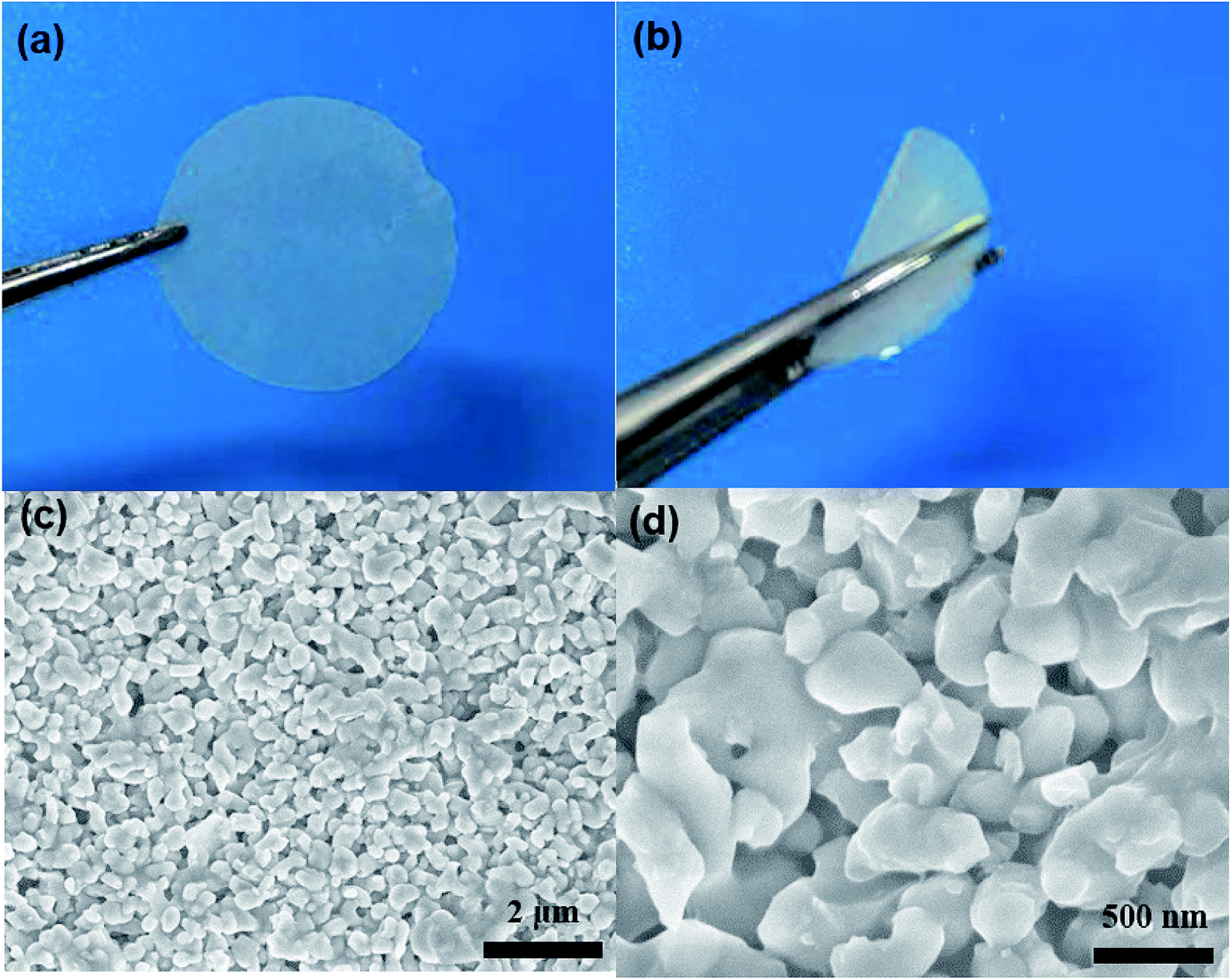 | ||
| Fig. 1 (a and b) Optical images of flat and curved QCE-P membrane, and (c and d) SEM images of the QCE-P membrane. | ||
Thermal stability is a crucial factor for practical applications of SSEs. To evaluate the thermal stability, the QCE-P membrane and commercial Celgard C480 separator were heated in a blast oven in air at 150 °C for 2 h. Fig. 2a and b compare the appearance changes of the two membranes before and after thermal treatment. The QCE-P membrane shows a minor change after heating in air, while the Celgard C480 separator shows an obvious shrinkage when heated under the same condition. It suggests that the QCE-P membrane is mechanically more robust than the commercial separator at elevated temperature, so as to avoid short-circuit and the accompanied safety issues.41 At a high temperature, flammability becomes a fatal defect of carbonate electrolytes to cause accidents. In this regard, F-containing FEC and HFE and P-containing TEP in QCE-P can act as effective fire extinguishers.42 As shown in Fig. 2c and d, when membranes are put above the flame, the QCE-P membrane does not support combustion at all (>10 s), which is distinguished from the QCE-base membrane that burns fiercely in 2 s. ESI Videos 1 and 2† also vividly proves the extinguishing capability of QCE-P. As a result, the QCE-P membrane can act as a thermally stable and nonflammable electrolyte for quasi-solid-state batteries.
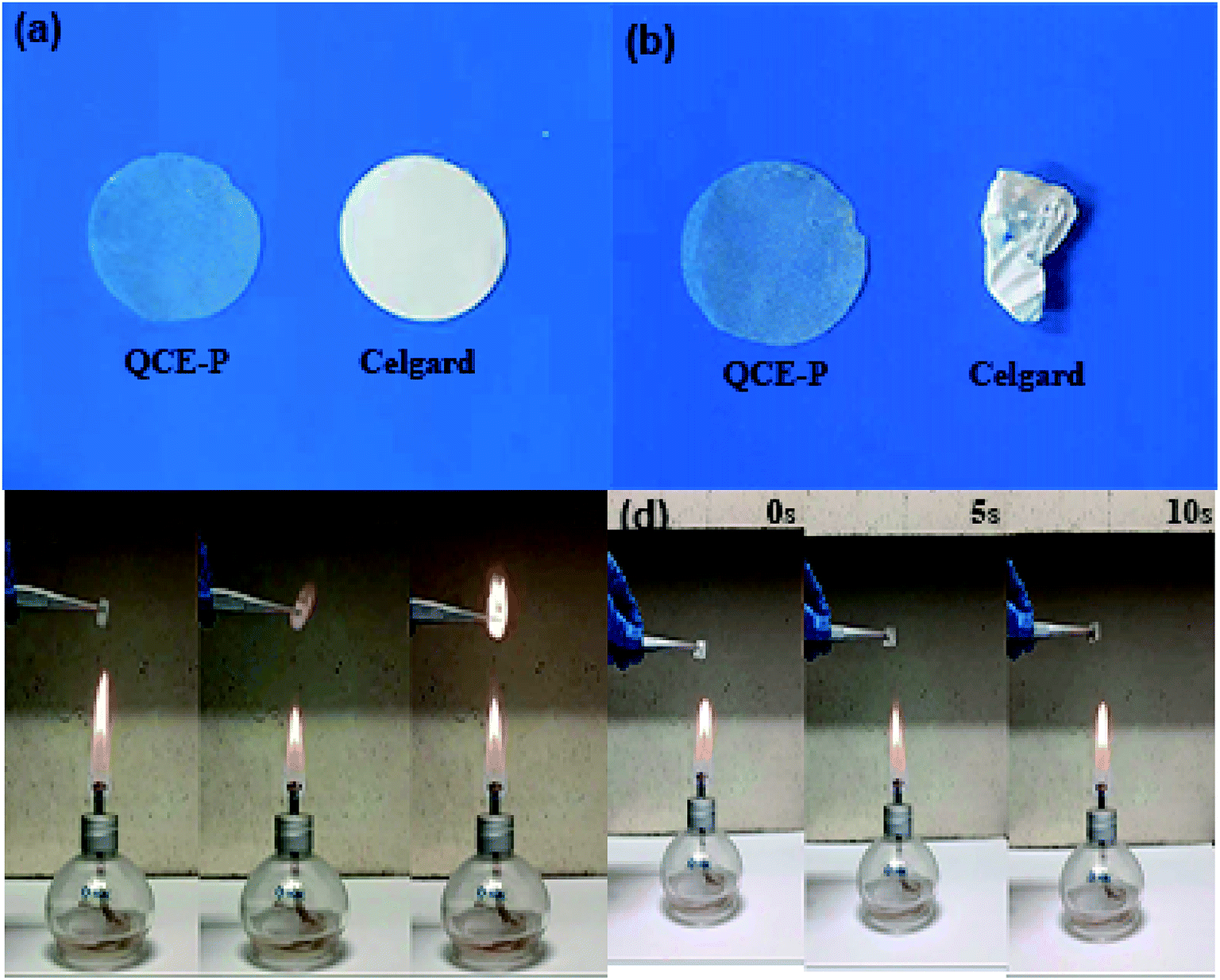 | ||
| Fig. 2 Photographs of QCE-P membrane and Celgard C480 separator at (a) room temperature and (b) 150 °C for 2 h in air, and flame tests of (c) QCE-base membrane and (d) QCE-P membrane. | ||
Fig. 3a shows the impedance spectrum for SS/QCE/SS cell, which is fitted by a equivalent circuit (inset in Fig. 3a) composed of bulk electrolyte resistance (Re), geometric capacitance (Q1) and electrode/electrolyte interfacial resistance (Q2).25 The ionic conductivity of QCE-P is 2.8 × 10⁻⁴ S cm−1 at room temperature and 7.8 × 10⁻⁴ S cm−1 at 60 °C, which are comparable with those for quasi-solid-state electrolyte.5 The temperature dependence of ionic conductivity from 30 to 80 °C is illustrated in Fig. 3b. The obtained results agree well with the typical Arrhenius equation.43
 | (1) |
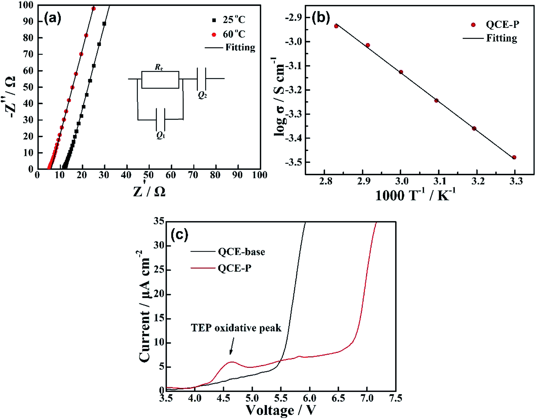 | ||
| Fig. 3 (a) EIS of QCE-P at room temperature and 60 °C, (b) temperature dependent ionic conductivity of QCE-P, and (c) comparison of LSV curves of QCE-base and QCE-P in the first sweeping. | ||
To further investigate the interfacial impedance between QCE-P and electrodes, EIS test of the Li/QCE-P/LCO cell was carried out. Fig. 4a displays the Nyquist plot and the corresponding equivalent circuit. There are two semicircles in the spectrum, which is due to the surface film resistance (Rf) and charge transfer resistance (Rct). The intersection of the first semicircle at the real axis stands for bulk electrolyte resistance (Re).31 As can be seen from Fig. 4a, QCE-P has a comparatively low interfacial resistance of 16 Ω, indicating that SEI and CEI layers from electrolyte decomposition are thin enough to provide fast Li-ion diffusion channels. In addition, the result shows that the cell also has a low Rct of 65 Ω. A CV test was also conducted between 3.0–4.2 V to study the reaction mechanism of LCO-based quasi-solid-state cell (Fig. 4b), where the anodic and cathodic peaks correspond to charge/discharge plateaus. The stronger oxidation and reduction currents in the first circle are related to degradation of part of the TEP and FEC, respectively.
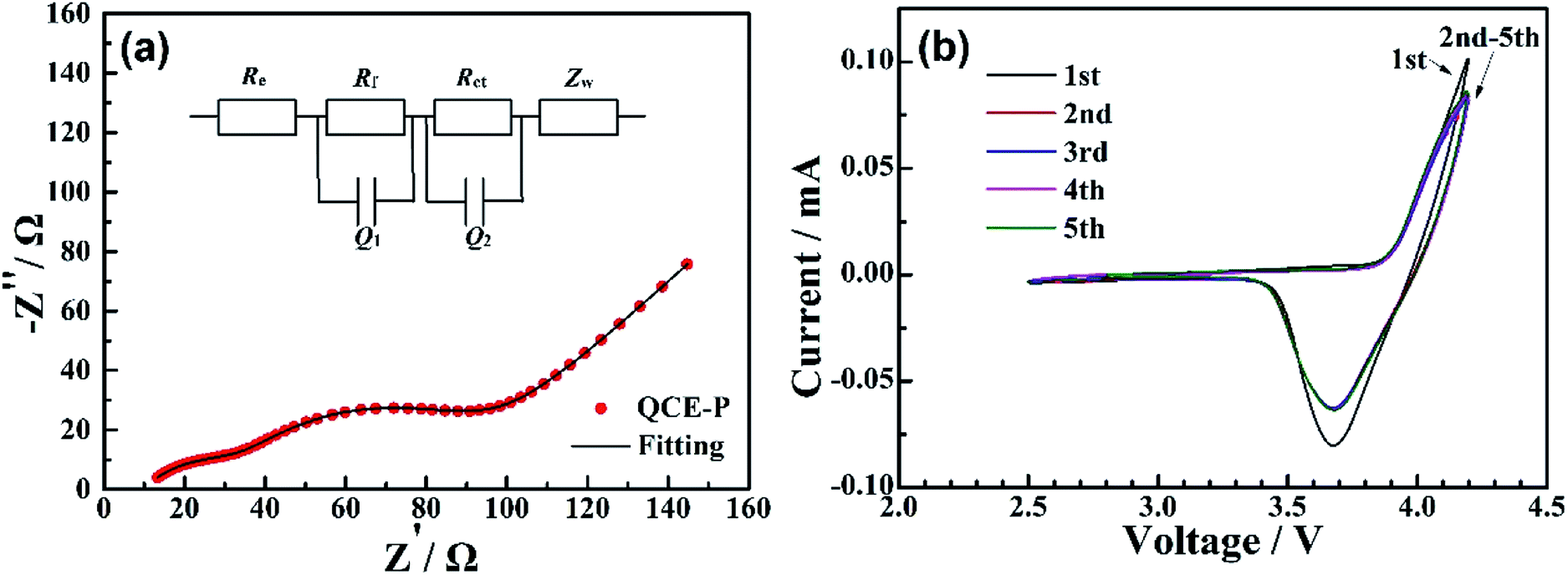 | ||
| Fig. 4 (a) EIS and (b) CV plots for LCO-based quasi-solid-sate cells using QCE-P. | ||
Electrochemical performance of lithium cells with the QCE-P electrolyte was evaluated by using LCO and NMC811 cathodes tested at 60 °C. Fig. 5a shows the charge/discharge profiles of LCO cell from 0.1C to 10C (1C is defined as 137 mA g−1). The polarization voltages between charge and discharge process increase and voltage plateaus become blurred as the current density increases, because the interfacial electrochemical polarization and concentration polarization in cathode increase steadily.46 The maximum discharge capacity of LCO with QCE-P at 0.1C is 136.3 mA h g−1, which is close to the theoretical capacity of LCO charged to 4.2 V (∼140 mA h g−1). The discharge capacities of LCO with QCE-P at 0.5C, 1C and 2C are 128.9 and 121.7 and 110.5 mA h g−1, respectively, higher than that with QCE-base. As seen in Fig. 5b, the merit of using QCE-P becomes more obvious as the current density increases to 5C and 10C, where the cell still has a relatively high specific capacity of 87.6 and 60.3 mA h g−1, respectively. The gradual increase in capacity with cycling at 0.1C, 0.5C and 1C can be ascribed to the increased activation of the interface between the electrolyte and electrodes. When the current density returns to 1C, the discharge capacity increases to 120.8 mA h g−1, indicating excellent reversibility of the cell. The cycling stability of the cell was evaluated at 1C after activation at 0.1C for 10 cycles and 0.5C for 5 cycles. As shown in Fig. 5c, the QCE-P cell also exhibits improved cycle performance compared with the QCE-base cell. After 180 cycles at 1C, the cell with QCE-P has a 78.7% retention, while the retention of the cell with QCE-base is only 59.2%. This behavior indicates that QCE-P electrolyte and its interfaces with the electrodes are stable during repeated cycling.
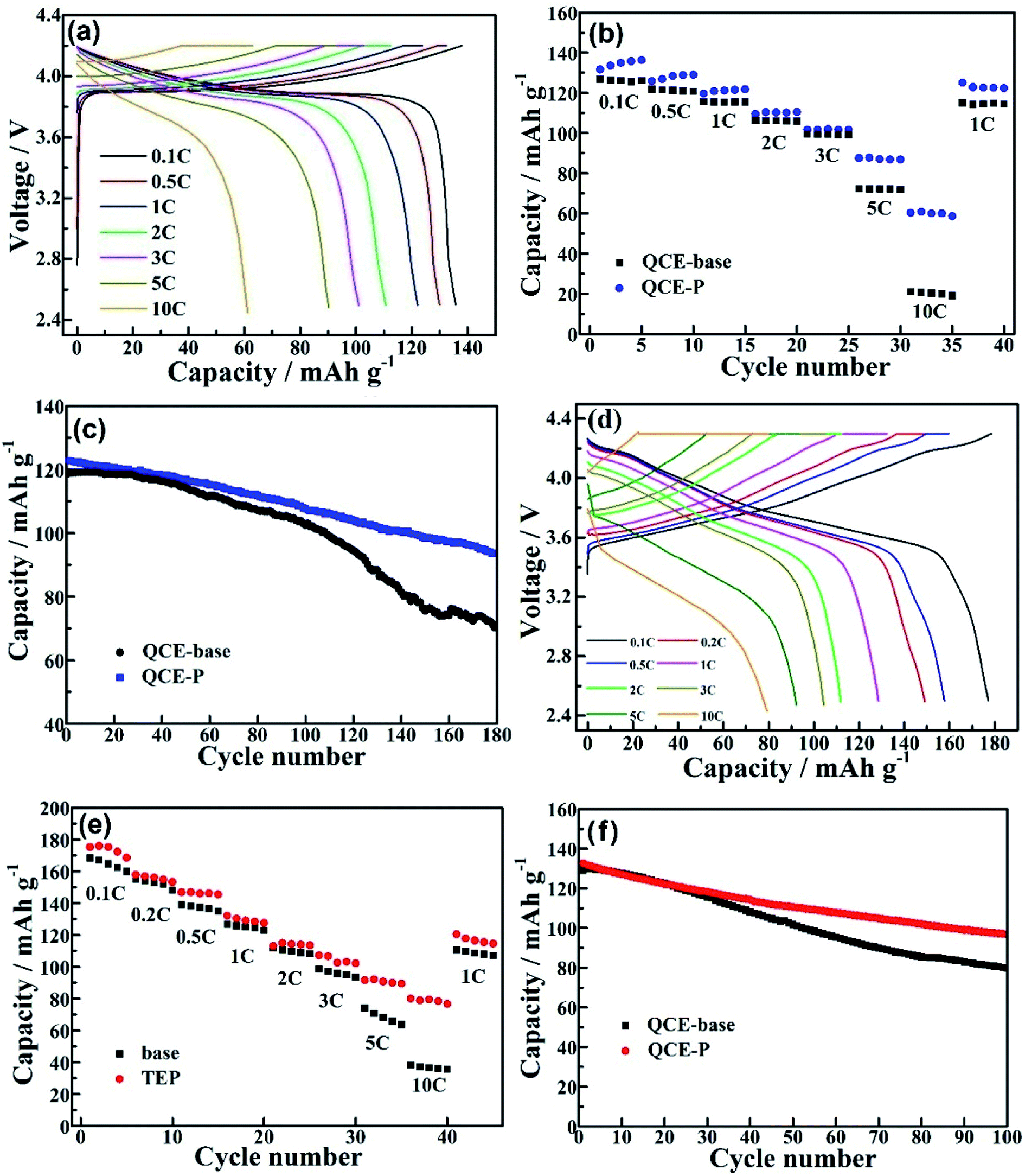 | ||
| Fig. 5 (a) Voltage profiles of LCO cell with QCE-P, comparison of (b) rate capability and (c) cycling performance (1C) of LCO cells with QCE-P and QCE-base, (d) voltage profiles of NMC811 cell with QCE-P, and comparison of (e) rate capability and (f) cycling performance (1C) of NMC811 cells with QCE-P and QCE-base. | ||
The electrochemical performance of the cells with more aggressive NMC811 cathode was also investigated. A high discharge capacity of 177.2 mA h g−1 is obtained at 0.1C (1C is defined as 180 mA g−1) for the NMC cell with QCE-P as seen in Fig. 5d. The capacity is on the decrease with increasing the current density. However, a discharge capacity of 79.2 mA h g−1 is still obtained at 10C. In contrast, the NMC811 cell with QCE-base has a discharge capacity of only 35.8 mA h g−1 at 10C (Fig. 5e). The enhanced rate capability can be ascribed to increased Li-ion conductivity in the QCE-P bulk and the interface between QCE-P and the electrodes. As shown in Fig. 5f, although the cycling stability of NMC811 cathode is relatively poor owing to severe transition metal dissolution, easier electrolyte degradation and lattice structure damage problems,47 the QCE-P cell still shows a relatively high capacity retention of 73% after 100 cycles, while the cell with QCE-base has a retention of only 60.9%.
To better understand the reason why cells using different electrolytes show huge difference in cell performance, the Li anodes were observed by SEM after 100 cycles from the NMC811 cells. Fig. 6a shows that lithium dendrites grow vertically into column-like microstructure when Li was repeated cycled in QCE-base. The conventional carbonate electrolyte is not compatible with Li anode, where a large proportion of electrolyte irreversibly reacts with Li to produce a thick SEI layer which insulates dead Li from electronic contact with the rest of the Li. However, in the case of QCE-P, an efficient SEI layer forms from the decomposition of the F- and P-containing plasticizers in QCE-P. The SEI layer inhibits the further reactions between Li and the electrolyte and the growth of lithium dendrites. A smooth Li surface is thus obtained as seen in Fig. 6b. As a result, the cell with QCE-P shows stable cycling with a stable SEI layer on Li.
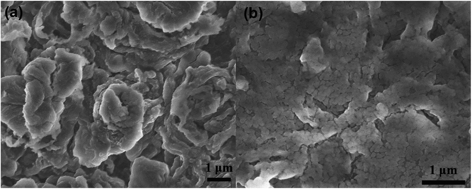 | ||
| Fig. 6 SEM images of the top of Li anode after 100 cycles from NMC811 cells with (a) QCE-base and (b) QCE-P electrolyte. | ||
Fig. 7a and b compare digital images of electrolytes after cycling in the NMC811 cells. Obvious side products can be seen on the surface of QCE-base (the brown area in Fig. 7a) with the side reactions between the electrolyte and the electrodes. By contrast, QCE-P should hardly react with the electrodes after the formation of efficient the SEI and CEI layers, leaving a clean surface of the electrolyte (Fig. 7b). To understand the effect of F-containing FEC and HFE and P-containing TEP on the chemical compositions of the SEI and CEI, XPS characterizations were conducted on the cycled NMC811 cathodes. Fig. 7c and d compare the P 2p and F 1s XPS of the cathodes cycled in different electrolytes. For the cathode with QCE-P, the peak at 133.6 eV corresponds to the formation of Li3PO4 from the decomposition of TEP. For the cathode with QCE-base, the peak at 135 eV is ascribed to the formation of LixPOyFz from the decomposition of LiPF6. As the main decomposition product from TEP, Li3PO4 has been used to coat cathode materials or fill in gel electrolytes due to its wide electrochemical window.48 Thus, the relatively Li3PO4-rich CEI can prevent further decomposition of the electrolyte on the cathode. This stabilization effect of cathode surface is also supported by the F 1s spectrum. The surface of the cycled NMC811 cathode contains much less LiPF6 decomposition species like LixPOyFz and LiF. Owing to less content of electronically insulating LiF, the QCE-P cell has a lower charge transfer impedance after cycling and exhibits better rate performance than the QCE-base cell. In addition, as shown in Fig. S3 (ESI†), the formation of a P and F-containing CEI layer is evident by the HAADF-STEM observation and EDS mapping on the cycled NMC811 particles.
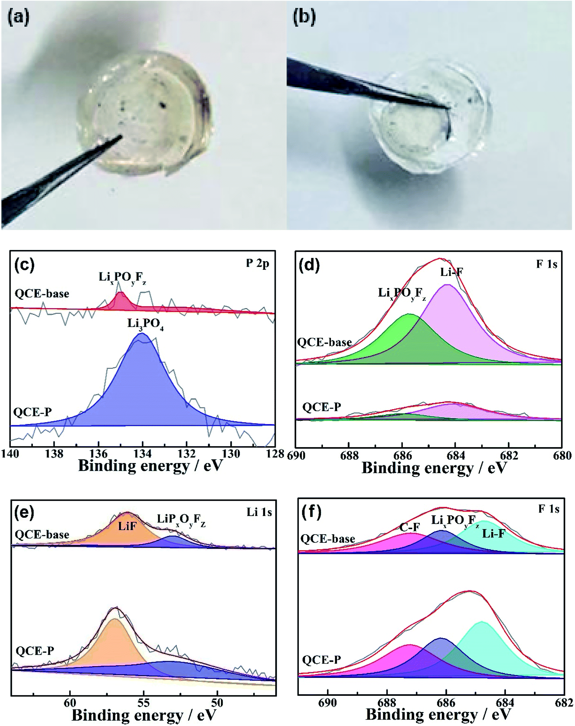 | ||
| Fig. 7 Optic photographs of the surface of (a) QCE-base and (b) QCE-P after cycling in the NMC811 cells, XPS of (c and d) NMC811 cathodes and (e and f) Li anodes cycled in different electrolytes. | ||
The chemical components of the SEI are mainly attributed to degradation of FEC, as it has a lower lowest unoccupied molecular orbital (LUMO) energy.44,45 Fig. 7e and f illustrate the Li 1s and F 1s spectra of the Li anodes cycled in QCE-base and QCE-P. Unlike the cathode side, species such as LiF and C–F from FEC reduction dominate the SEI. F-rich SEI is good electronic insulator and blocks the electron tunnel, making itself a pure ionic conductor to prevent continuous electrolyte consumption.49,50 In addition, LiF presents high interfacial energy to Li metal, which facilitates Li-ion migration along the interface and enables the deposition of metallic Li in the parallel direction.51 As a consequence, these substances act as efficient protective layer for Li anode, enabling a smooth Li surface and thereby slower capacity loss during cycling.
For NMC811 cathodes, surface phase transformation to rock-salt structure is another important mechanism for electrochemical failure. To investigate the degree of lattice reconfiguration, the NMC811 cell was charged to 4.3 V after 100 cycles, and then it was disassembled to check the change of valence state of Ni on the cathode surface using XPS (Fig. 8). The Ni 2p spectra show that there is more Ni4+ and less Ni2+ and Ni3+ on the NMC 811 cathode cycled in QCE-P than that in QCE-base. The presence of Ni2+ indicates the irreversible formation of the NiO-like rock-salt phase on the NMC811 cathode surface.52 This suggests that the CEI on NMC 811 can refrain lattice reconfiguration.
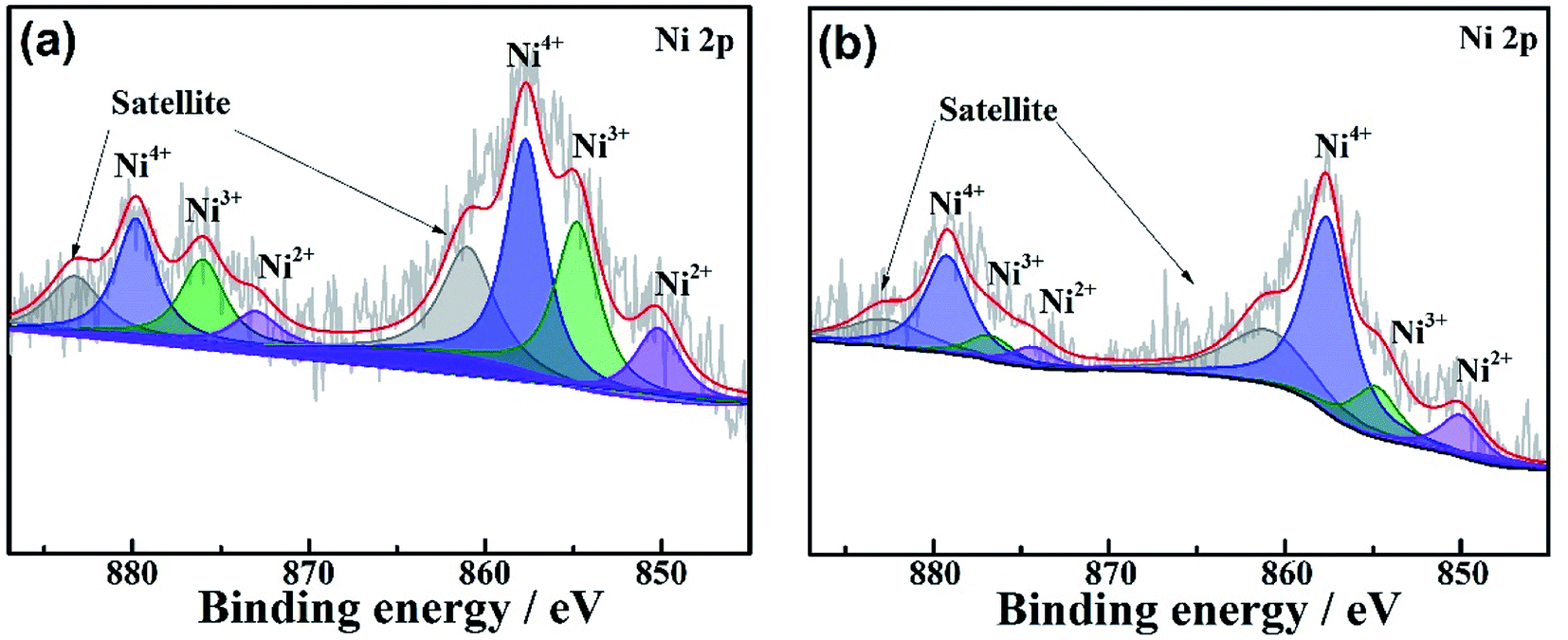 | ||
| Fig. 8 Comparison of XPS of NMC811 cathodes charged to 4.3 V after 100 cycles in (a) QCE-base and (b) QCE-P. | ||
Except for the use of F-rich and P-rich plasticizers, polymer matrix and LATP particles in QCE also play a vital role in cycling stability of cells. As shown in Fig. S4 (ESI†), the electrochemical properties of the LCO and NMC811 cells using liquid plasticizers-based electrolyte (1 M LiPF6 inFEC/HFE/TEP, 1:1:1 in volume) were also evaluated to verify the effect of polymer matrix and filler. Note that the liquid cells show poorer cycling stability with 89% retention for LCO and 78% retention for NMC811 after 50 cycles, comparing with the values for the QCE cells (95% for LCO and 83% for NMC811) after the same cycles. Thus, it can be concluded that the polymer and LATP further improve the cycling stability of the cells by alleviating the decomposition of the plasticizers, especially at relatively high temperature.
Cycling performance and abuse tests of the pouch-type LCO and NMC811 cells were also conducted. Fig. 9a and b give the voltage profiles and cycling performance of the LCO/graphite pouch cell. After 50 cycles at 0.5C, the cell can keep 81% of its initial capacity. As shown in Fig. 9c and d, the NMC811 cell can exhibit a moderate cycling stability at 0.5C (75% retention after 50 cycles) even using more aggressive LiNi0.8Mn0.1Co0.1O2 cathode and relatively thin Li foil anode (100 μm). As seen in Fig. 9e–h and ESI Videos 3–5,† blue LED lights can be still lighted after abuse tests of folding, cutting and nail penetration, which indicates good safety of the cells with the QCE-P composed of LATP/polymer composite and nonflammable plasticizers.
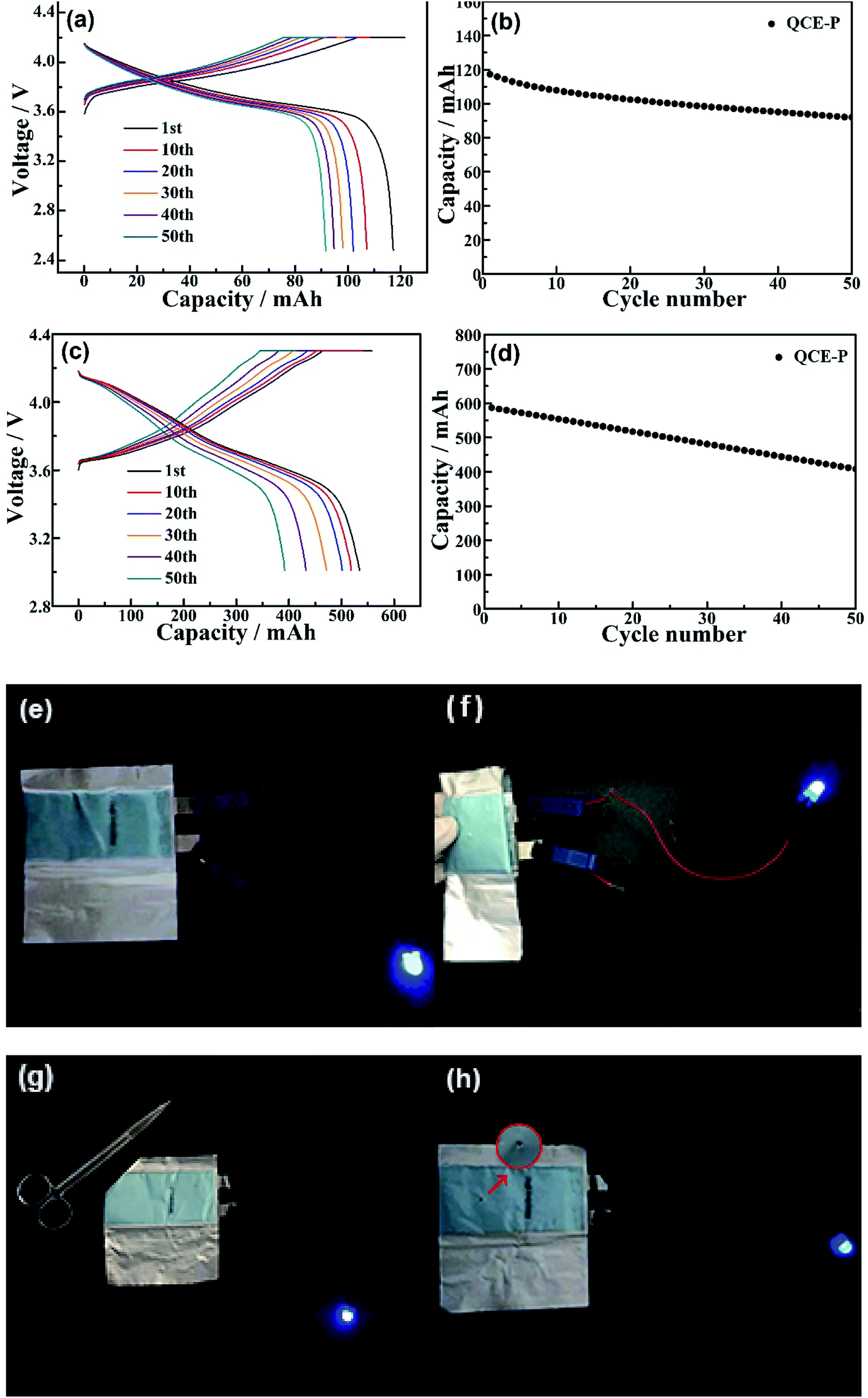 | ||
| Fig. 9 (a) Voltage profiles and (b) cycling performance of LCO/graphite pouch cell with QCE-P at 0.5C, (c) voltage profiles and (d) cycling performance of NMC811/Li pouch cell with QCE-P at 0.5C, and abuse tests of the NMC811/Li pouch cell under different conditions: (e) pristine, (f) folding, (g) cutting and (h) nail penetration. | ||
4. Conclusions
In summary, we developed a novel QCE, which is composed of PETPTA polymer matrix, LATP inorganic fillers, LiPF6 salt and FEC/TEP/HFE plasticizers. This QCE shows good flexibility, moderate room-temperature ionic conductivity and nonflammability. Lithium metal cells assembled with QCE deliver high capacity and show stable cycling at 60 °C. The LCO cell with QCE can keep 78.7% of its initial capacity after 180 cycles and the NMC811 cell holds 73% capacity after 100 cycles at 1C rate. The LiF and C–F species in situ formed from the decomposition of FEC protect Li anode, while Li3PO4 derived from TEP stabilizes the electrolyte/cathode interface, bringing in long cycle life of lithium metal cells. Also, LCO/graphite and NMC811/Li pouch cells show respective 81% and 75% capacity retention at 0.5C after 50 cycles at 60 °C, and show a good safety bearing abuse tests of folding, cutting and nail penetration. This work will shed light on the design of safe, stable solid electrolytes for high-performance Li metal batteries.Conflicts of interest
There are no conflicts to declare.Acknowledgements
This work was supported by the National Natural Science Foundation of China (No. 51572238), and Zhejiang Provincial Natural Science Foundation of China under Grant no. LY19E020013.References
- J. B. Goodenough and K. S. Park, J. Am. Chem. Soc., 2013, 135, 1167–1176 CrossRef CAS PubMed.
- G. M. Zhou, F. Li and H. M. Cheng, Energy Environ. Sci., 2014, 7, 1307–1338 RSC.
- J. W. Choi and D. Aurbach, Nat. Rev. Mater., 2016, 1, 16013 CrossRef CAS.
- D. C. Lin, Y. Y. Liu and Y. Cui, Nat. Nanotechnol., 2017, 12, 194–206 CrossRef CAS PubMed.
- X. B. Cheng, R. Zhang, C. Z. Zhao and Q. Zhang, Chem. Rev., 2017, 117, 10403–10473 CrossRef CAS PubMed.
- X. Li, J. M. Zheng, M. H. Engelhard, D. H. Mei, Q. Y. Li, S. H. Jiao, N. Liu, W. G. Zhao, J. G. Zhang and W. Xu, ACS Appl. Mater. Interfaces, 2018, 10, 2469–2479 CrossRef CAS PubMed.
- W. Xu, J. L. Wang, F. Ding, X. L. Chen, E. Nasybulin, Y. H. Zhang and J. G. Zhang, Energy Environ. Sci., 2014, 7, 513–537 RSC.
- E. M. Erickson, F. Schipper, T. R. Penki, J. Y. Shin, C. Erk, F. F. Chesneau, B. Markovsky and D. Aurbach, J. Electrochem. Soc., 2017, 164, A6341–A6348 CrossRef CAS.
- A. Manthiram, J. C. Knight, S. T. Myung, S. M. Oh and Y. K. Sun, Adv. Energy Mater., 2016, 6, 1501010 CrossRef.
- M. T. F. Rodrigues, G. Babu, H. Gullapalli, K. Kalaga, F. N. Sayed, K. Kato, J. Joyner and P. M. Ajayan, Nat. Energy, 2017, 2, 17108 CrossRef CAS.
- M. D. Radin, S. Hy, M. Sina, C. C. Fang, H. D. Liu, J. Vinckeviciute, M. H. Zhang, M. S. Whittingham, Y. S. Meng and A. Van der Ven, Adv. Energy Mater., 2017, 7, 1602888 CrossRef.
- J. B. Goodenough and Y. Kim, Chem. Mater., 2010, 22, 587–603 CrossRef CAS.
- J. Q. Dai, C. P. Yang, C. W. Wang, G. Pastel and L. B. Hu, Adv. Mater., 2018, 30, 1802068 CrossRef PubMed.
- K. Xu, Chem. Rev., 2014, 114, 11503–11618 CrossRef CAS PubMed.
- S. Choudhury, R. Mangal, A. Agrawal and L. A. Archer, Nat. Commun., 2015, 6, 10101 CrossRef CAS PubMed.
- S. K. Jeong, H. Y. Seo, D. H. Kim, H. K. Han, J. G. Kim, Y. B. Lee, Y. Iriyama, T. Abe and Z. Ogumi, Electrochem. Commun., 2008, 10, 635–638 CrossRef CAS.
- R. Tao, X. X. Bi, S. Li, Y. Yao, F. Wu, Q. Wang, C. Z. Zhang and J. Lu, ACS Appl. Mater. Interfaces, 2017, 9, 7003–7008 CrossRef CAS PubMed.
- M. Gauthier, T. J. Carney, A. Grimaud, L. Giordano, N. Pour, H. H. Chang, D. P. Fenning, S. F. Lux, O. Paschos, C. Bauer, F. Maglia, S. Lupart, P. Lamp and Y. Shao Horn, J. Phys. Chem. Lett., 2015, 6, 4653–4672 CrossRef CAS PubMed.
- C. S. Yoon, H. H. Ryu, G. T. Park, J. H. Kim, K. H. Kim and Y. K. Sun, J. Mater. Chem. A, 2018, 6, 4126–4132 RSC.
- M. M. Chen, E. Y. Zhao, D. F. Chen, M. M. Wu, S. B. Han, Q. Z. Huang, L. M. Yang, X. L. Xiao and Z. B. Hu, Inorg. Chem., 2017, 56, 8355–8362 CrossRef CAS PubMed.
- J. C. Chai, Z. H. Liu, J. Ma, J. Wang, X. C. Liu, H. S. Liu, J. J. Zhang, G. L. Cui and L. Q. Chen, Adv. Sci., 2016, 4, 1600377 CrossRef PubMed.
- C. P. Yang, K. Fu, Y. Zhang, E. Hitz and L. B. Hu, Adv. Mater., 2017, 29, 1701169 CrossRef PubMed.
- W. Q. Zhang, J. H. Nie, L. Fan, Z. L. Wang and C. W. Sun, Nano Energy, 2018, 45, 413–419 CrossRef CAS.
- A. Varzi, R. Raccichini, S. Passerini and B. Scrosati, J. Mater. Chem. A, 2016, 4, 17251–17259 RSC.
- Y. R. Zhao, C. Wu, G. Peng, X. T. Chen, X. Y. Yao, Y. Bai, F. Wu, S. J. Chen and X. X. Xu, J. Power Sources, 2016, 301, 47–53 CrossRef CAS.
- Y. Q. Chen, Y. Luo, H. Z. Zhang, C. Qu, H. M. Zhang and X. F. Li, Small Methods, 2019, 3, 1800551 CrossRef.
- N. Kamaya, K. Homma, Y. Yamakawa, M. Hirayama, R. Kanno, M. Yonemura, T. Kamiyama, Y. Kato, S. Hama, K. Kawamoto and A. Mitsui, Nat. Mater., 2011, 10, 682–686 CrossRef CAS PubMed.
- Y. Kato, S. Hori, T. Saito, K. Suzuki, M. Hirayama, A. Mitsui, M. Yonemura, H. Iba and R. Kanno, Nat. Energy, 2016, 1, 16030 CrossRef CAS.
- C. W. Sun, J. Liu, Y. D. Gong, D. P. Wilkinson and J. J. Zhang, Nano Energy, 2017, 33, 363–386 CrossRef CAS.
- W. Xiao, J. Y. Wang, L. L. Fan, J. J. Zhang and X. F. Li, Energy Storage Materials, 2019, 19, 379–400 CrossRef.
- D. Xu, J. M. Su, J. Jin, C. Sun, Y. D. Ruan, C. H. Chen and Z. Y. Wen, Adv. Energy Mater., 2019, 9, 1900611 CrossRef.
- H. Y. Huo, Y. Chen, J. Luo, X. F. Yang, X. X. Guo and X. L. Sun, Adv. Energy Mater., 2019, 9, 1804004 CrossRef.
- Q. J. Wang, W. L. Song, L. Z. Fan and Y. Song, J. Membr. Sci., 2015, 492, 490–496 CrossRef CAS.
- H. H. Fan, H. X. Li, L. Z. Fan and Q. Shi, J. Power Sources, 2014, 249, 392–396 CrossRef CAS.
- H. Duan, Y. X. Yin, X. X. Zeng, J. Y. Li, J. L. Shi, Y. Shi, R. Wen, Y. G. Guo and L. J. Wan, Energy Storage Materials, 2018, 10, 85–91 CrossRef.
- N. Chen, Y. J. Dai, Y. Xing, L. L. Wang, C. Guo, R. J. Chen, S. J. Guo and F. Wu, Energy Environ. Sci., 2017, 10, 1660–1667 RSC.
- J. X. Zhang, N. Zhao, M. Zhang, Y. Q. Li, P. K. Chu, X. X. Guo, Z. F. Di, X. Wang and H. Li, Nano Energy, 2016, 28, 447–454 CrossRef CAS.
- D. H. Kim, B. Kang and H. Lee, J. Power Sources, 2019, 423, 137–143 CrossRef CAS.
- S. R. Chen, J. M. Zheng, D. H. Mei, K. S. Han, M. H. Engelhard, W. G. Zhao, W. Xu, J. Liu and J. G. Zhang, Adv. Mater., 2018, 30, 1706102 CrossRef PubMed.
- S. Takase, C. Kubo, R. Aono and Y. Shimizu, J. Sol-Gel Sci. Technol., 2016, 79, 564–572 CrossRef CAS.
- W. Fan, X. L. Zhang and C. J. Li, ACS Appl. Energy Mater., 2019, 2, 5292–5299 CrossRef CAS.
- X. L. Fan, L. Chen, O. Borodin, X. Ji, J. Chen, S. Hou, T. Deng, J. Zheng, C. Y. Yang, S. C. Liou, K. Amine, K. Xu and C. S. Wang, Nat. Nanotechnol., 2018, 13, 715–722 CrossRef CAS PubMed.
- Q. Ma, X. X. Zeng, J. P. Yue, Y. X. Yin, T. T. Zuo, J. Y. Liang, Q. Deng, X. W. Wu and Y. G. Guo, Adv. Energy Mater., 2019, 9, 1803854 CrossRef.
- Y. K. Han, J. Yoo and T. Yim, RSC Adv., 2017, 7, 20049–20056 RSC.
- L. Chen, X. L. Fan, E. Y. Hu, X. Ji, J. Chen, S. Hou, T. Deng, J. Li, D. Su, X. Q. Yang and C. S. Wang, Chem, 2019, 5, 896–912 CAS.
- L. Zhao, Y. Huang, B. Liu, Y. X. Huang, A. M. Song, Y. H. Lin, M. S. Wang, X. Li and H. J. Cao, Electrochim. Acta, 2018, 278, 1–12 CrossRef CAS.
- F. Lin, D. Nordlund, I. M. Markus, T. C. Weng, H. L. Xin and M. M. Doeff, Energy Environ. Sci., 2014, 7, 3077–3085 RSC.
- S. W. Baek, I. Honma, J. Kim and D. Rangappa, J. Power Sources, 2017, 343, 22–29 CrossRef CAS.
- Q. L. Zhang, J. Pan, P. Lu, Z. Y. Liu, M. W. Verbrugge, B. W. Sheldon, Y. T. Cheng, Y. Qi and X. C. Xiao, Nano Lett., 2016, 16, 2011–2016 CrossRef CAS PubMed.
- K. Leung, J. Phys. Chem. C, 2013, 117, 1539–1547 CrossRef CAS.
- J. L. Hu, K. Y. Chen and C. L. Li, ACS Appl. Mater. Interfaces, 2018, 10, 34322–34331 CrossRef CAS PubMed.
- S. H. Lee, J. Y. Hwang, S. J. Park, G. T. Park and Y. K. Sun, Adv. Funct. Mater., 2019, 29, 1902496 CrossRef.
Footnote |
| † Electronic supplementary information (ESI) available: Cross-section SEM image of the quasi-solid-state cell, LSV curves of QCE-P after the first sweeping, HAADF-STEM image and EDS mapping of the cycled NMC811 particle, cycling performance LCoO2 and NMC811 cells in the non-flammable liquid electrolyte, and abuse tests of the QCE film and the NMC811 pouch cell. See DOI: 10.1039/c9ra08677c |
| This journal is © The Royal Society of Chemistry 2019 |