DOI:
10.1039/C9RA08571H
(Paper)
RSC Adv., 2019,
9, 38703-38712
The effect of the surface coating of a strontium mono-aluminate europium dysprosium-based (SrAl2O4:Eu2+,Dy3+) phosphor by polyethylene (PE), polystyrene (PS) and their dual system on the photoluminescence properties of the pigment
Received
20th October 2019
, Accepted 11th November 2019
First published on 27th November 2019
Abstract
SrAl2O4:Eu2+,Dy3+ as a known strontium mono-aluminate europium dysprosium-based phosphor is widely used in paints and coating formulations as a photoluminescence pigment. It has two major drawbacks: improper dispersion in organic-based paints and weak water and moisture resistance. To address the above-mentioned drawbacks, the surface coating of phosphors with polyethylene and polystyrene individually and in combination using a solution technique was performed. The FT-IR spectra showed that the used polymers were coated on the phosphor properly. Also, the EDS spectra showed the presence of elemental carbon for the treated phosphors with different amounts. No regular trend was observed for element ratios when the polyethylene content in the coating layer was reduced from 100 to 0%. Based on the XRD patterns, the crystalline structure of the coated phosphors was not affected by the polymeric coated layer. In the SEM micrographs, the sharp and rough edges of the uncoated phosphor changed to a smooth and soft state for the coated phosphors. The brightness of most of the coated phosphors was independent of time and did not change over a period of 5 minutes after UV irradiation. This property makes the polymeric coated phosphors suitable as photoluminescence pigments in all kinds of paints and coatings.
1. Introduction
SrAl2O4:Eu2+,Dy3+ as a known strontium mono-aluminate europium dysprosium-based phosphor is widely used in paints and coating formulations as a photoluminescence pigment. It has several useful properties including brightness, non-radioactivity, high fluorescence intensity and long afterglow time.1 It also emits blue-green light in the dark after light excitation at wavelengths ranging from 200 to 450 nm.2 This luminescence pigment has an inorganic part named SrAl2O4, which acts as the host to store the excitation energy, and two earth elements as activated doping ions, which are known as activators (Eu2+ and Dy3+) to give radiation after excitation.3 However, the fast hydrolysis of this pigment results in O–Sr–O bond breaking and subsequently, it destroys the material.4 To avoid this above-mentioned drawback, the phosphor is encapsulated with several inorganic and/or organic materials.5–15 The luminous intensity of the coated pigment depends on the dispersion of the pigment (phosphor) in the polymer (paint) matrix.16 However, because SrAl2O4:Eu2+,Dy3+ is a mineral material, it's dispersion in an organic (polymeric) base paint matrix and the fast hydrolysis of this pigment in waterborne environments are major drawbacks.17 The encapsulation (coating) of SrAl2O4:Eu2+,Dy3+ with an organic material, i.e., a polymer or polymer blend improves the dispersion state of the pigment in the organic paint because of chemical structure similarity. Mishra et al.18 coated the surface of SrAl2O4:Eu2+,Dy3+ with ethyl vinyl acetate (EVA). They found that the EVA-coated pigment particles achieved a uniform dispersion. In another attempt,19 the researchers used other polymers including several grades of polyethylene, polypropylene and a copolymer of polypropylene and methyl acrylate. They found different effects of used polymers on the photoluminescence properties of the coated phosphor. Peng and his colleagues20 investigated the water resistance of coated alkaline-earth–rare earth–aluminate phosphors with poly(methyl methacrylate) (PMMA). They concluded that the water-resistance property improved remarkably because the organic parts were grafted onto the phosphor surface. The surface modification of the SrAl2O4:Eu2+,Dy3+ phosphor by methylmethacrylate (MMA) was done by Xingdong Lü and co-workers21 using methylamino propyl trimethoxy silane (MAPS) as a coupling agent. They claimed that the water resistance of the modified phosphor was much better than that of the unmodified phosphor. Other researchers22–40 also reported improvement in the phosphor properties, i.e., water resistance and photoluminescence intensities when the SrAl2O4:Eu2+,Dy3+ surface was coated with other polymers and chemicals and via different technologies. Polyethylene (PE) and polystyrene (PS) are two common thermoplastics. They are cheap, safe and accessible in commercial scales. Considering the above-mentioned parameters and also their organic nature, it seemed that they can be suitable volunteers as a cover layer on the phosphor surface to reduce the aforementioned drawbacks of the SrAl2O4:Eu2+,Dy3+ phosphor. However, to the best of our knowledge, there is no systematic research on the effects of coating the SrAl2O4:Eu2+,Dy3+ phosphor surface by polyethylene (PE) or polystyrene (PS) individually or in combination on the photoluminescence properties and water resistance of the above-mentioned phosphor.
2. Experimental
2.1. Materials
Low-density polyethylene (LDPE, Lupolen 2420D, AMIR KABIR petrochemical company, Bandar Emam, Iran) with density and melt flow rate (MFR, 190 °C/2.16 kg) of 0.923 g cm−3 and 0.25 g/10 min, respectively, was obtained. General-purpose polystyrene (GPPS, TJPS-G1551, TJPAPC, Assalouyeh, Iran) with density and melt flow rate (MFR, 200 °C/5 kg) of 1.04 g cm−3 and 9 g/10 min, respectively, commercial SrAl2O4:Eu2+,Dy3+ phosphor with a particle size of 50–75 μm and melting point of 1200 °C (emitting agent, Hangzhou Yeming Science & Technology Co. Ltd, China), and toluene (solvent, Merck, Germany) were obtained. Acrylic resin (ACROPOL™ 63-893, a high-molecular-weight vinyl acetate acrylic copolymer emulsion, Allnex, Germany) was also used.
2.2. Sample preparation and identification techniques
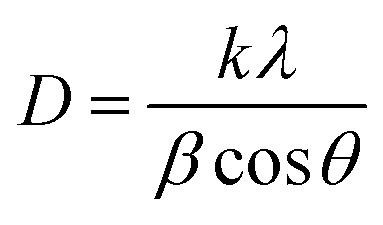
The coated phosphors were prepared by a solution method. First, 0.1 g polymer (PE, PS and/or a mix of them) was dissolved in 2 ml toluene by using a laboratory water bath. Subsequently, 2 g phosphor was added to the solution and continuously stirred until a homogeneous solution was obtained. Table 1 shows the prepared sample formulation. After this time collapsed, the dish content was spread on a glass strip to make a narrow film at room temperature before further investigations. The chemical structures of the un-treated and polymer-treated phosphors were assessed by attenuated total reflectance Fourier transform infrared spectroscopy (ATR-FTIR, AVATAR 370FT-IR, Termo Nicolet, USA) with 400–4000 cm−1 sweeping wavelength. Fig. 1 compares the FT-IR spectra of the un-treated phosphor and several SrAl2O4:Eu2+,Dy3+ phosphors treated by PE and PS. The elemental assessment of the phosphors was performed by an Energy-Dispersive X-ray Spectroscopy (EDS) instrument (7353, Oxford, UK) with 133 eV resolution. Table 2 and Fig. 2 show the results for all studied coated and uncoated phosphors. The angles and intensities of diffracted beams to phosphors were measured by an X-ray diffraction crystallography (XRD) instrument (GNR, Italy) with λ = 0.154 nm Cu Kα radiation at 40 kV tube voltage, 30 mA tube current, and scintillator as detector type under beam incident from 10 to 80°. Table 3 represents the average crystallite size of the untreated and treated phosphors measured by XRD using the Scherrer's equation41 as follows:| |
 | (1) |
Here, k is the Scherrer constant, λ is the X-ray wavelength, β is the peak width of half maximum, and θ is the Bragg diffraction angle.
Table 1 The PE–PS weight ratios in binary mixtures
| PE100 |
PE–PS |
100–00 |
| PE75 |
PE–PS |
75–25 |
| PE50 |
PE–PS |
50–50 |
| PE25 |
PE–PS |
25–75 |
| PE00 |
PE–PS |
00–100 |
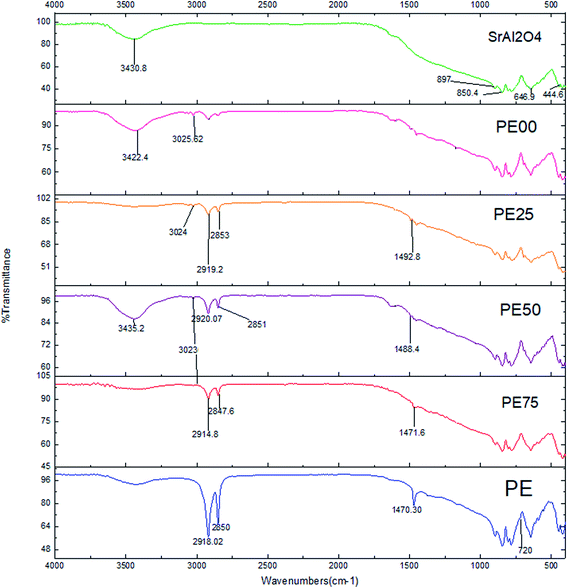 |
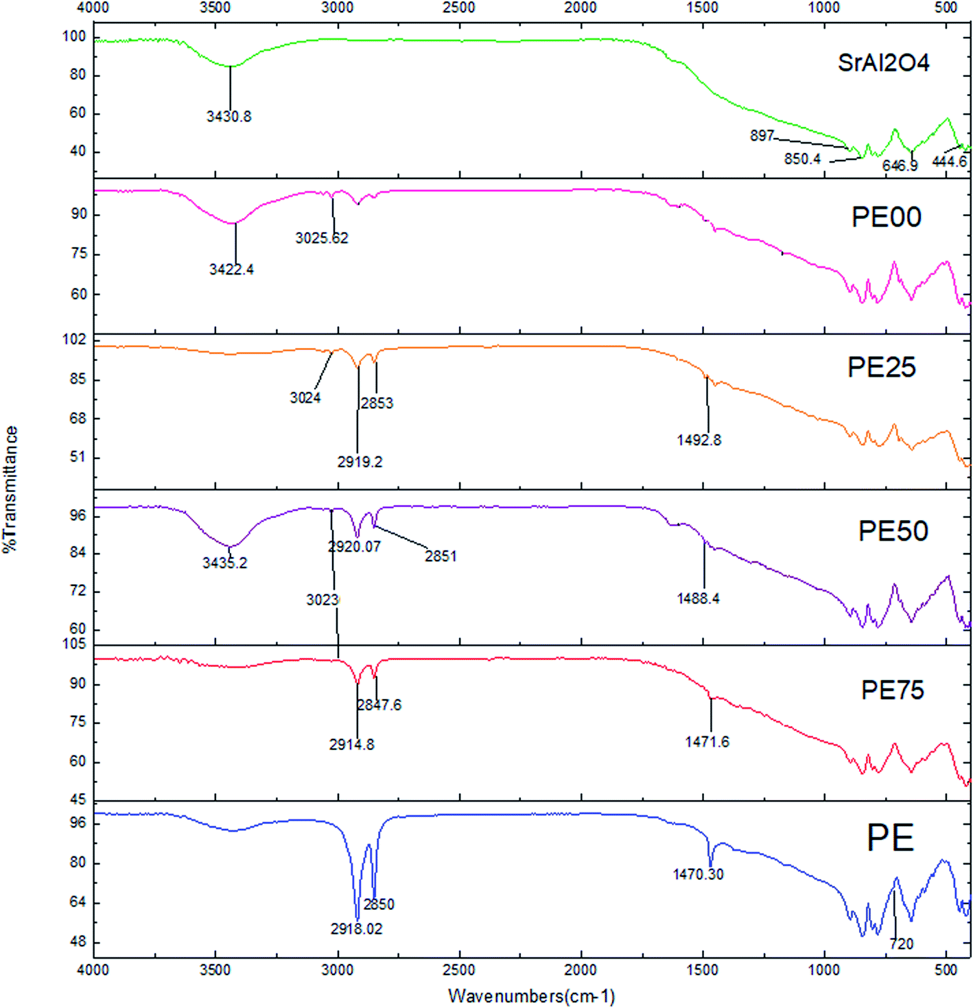
| | Fig. 1 The FT-IR spectra comparison between un-treated and several SrAl2O4:Eu2+,Dy3+ phosphors treated by PE and PS. | |
Table 2 The element wt% for uncoated and coated phosphors obtained by EDS
| Sample |
C |
O |
Al |
Sr |
| Un-coated |
— |
40 |
19 |
40 |
| PE100 |
60 |
10 |
10 |
20 |
| PE75 |
55 |
14 |
10 |
21 |
| PE50 |
20 |
23 |
20 |
37 |
| PE25 |
38 |
18 |
14 |
30 |
| PE00 |
34 |
17 |
18 |
31 |
 |
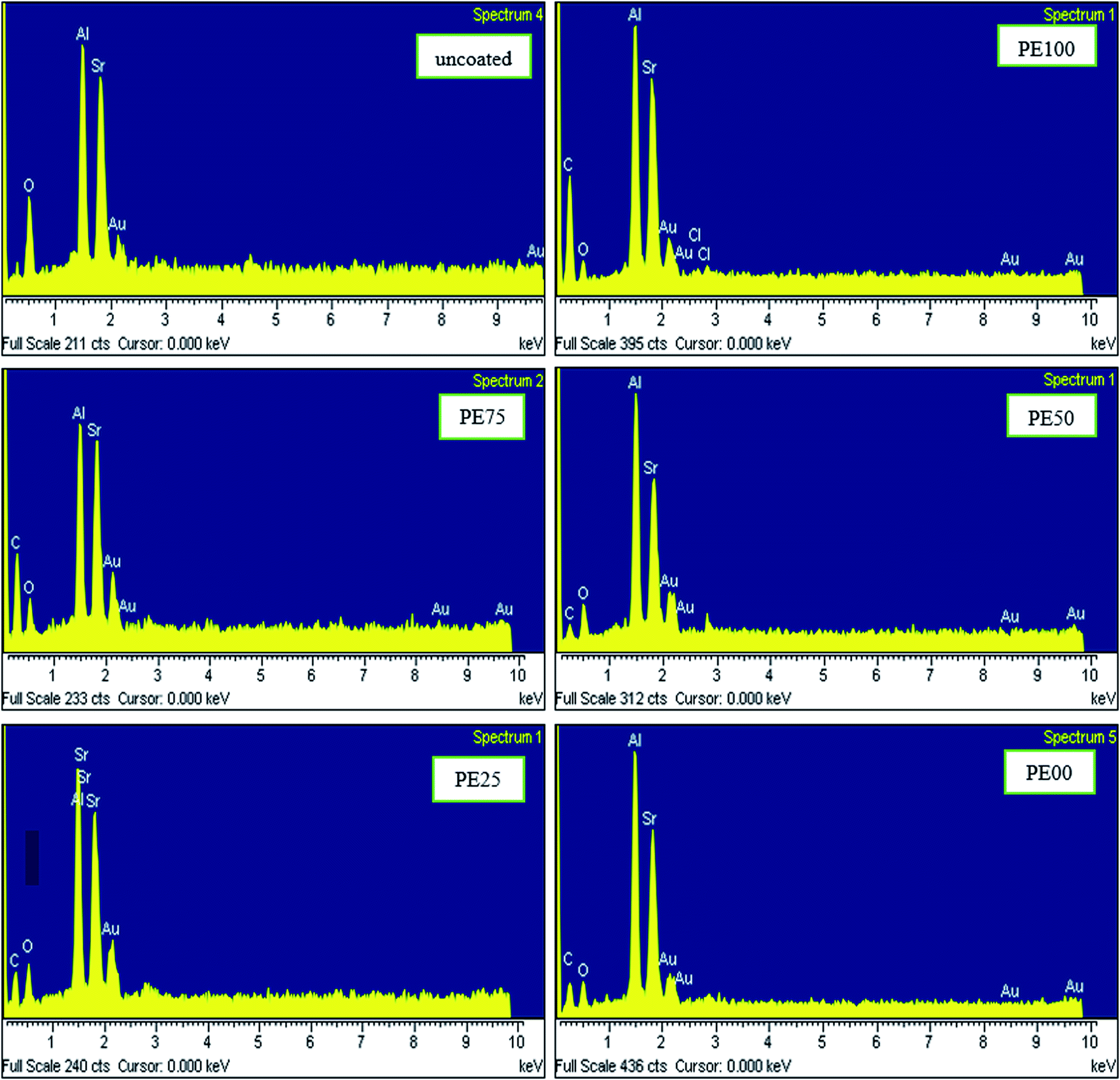
| | Fig. 2 The EDS spectra comparison between un-treated and several SrAl2O4:Eu2+,Dy3+ phosphors treated by PE and PS. | |
Table 3 The average crystallite size of the un-coated and polymer-coated SrAl2O4:Eu2+,Dy3+ phosphor crystals derived by the XRD technique
| Sample |
β (degree) |
2θ (degree) |
D (nm) |
| Un-coated |
0.55 |
29 |
14.7 |
| PE100 |
0.41 |
30 |
19.7 |
| PE75 |
0.41 |
30 |
19.7 |
| PE50 |
0.41 |
29 |
19.6 |
| PE25 |
0.53 |
29 |
15.3 |
| PE00 |
0.59 |
35 |
13.9 |
Fig. 3 compares the XRD patterns of the same studied phosphors. Also, a LEO 1450VP (Germany) field emission gun scanning electron microscope (SEM) with a resolution of 2.5 nm at 20 kv was used for the morphology study of the samples (Fig. 4). The TGA analysis was performed with 12 mg samples in the air atmosphere for swept temperatures of 25–950 °C and with 10 °C min−1 temperature rise. Fig. 5 compares the TGA curves of the untreated and several treated SrAl2O4:Eu2+,Dy3+ phosphors with various PE–PS ratios. After the phosphors were excited by a Xe lamp at 390 nm for 15 min at PMT voltage of 700 V and Ex slit of 10 nm, a fluorescence spectrophotometer (Cary Eclipse, VARIAN, USA) was used for recording afterglow decay photoluminescence spectra (Fig. 6 and 7).
 |
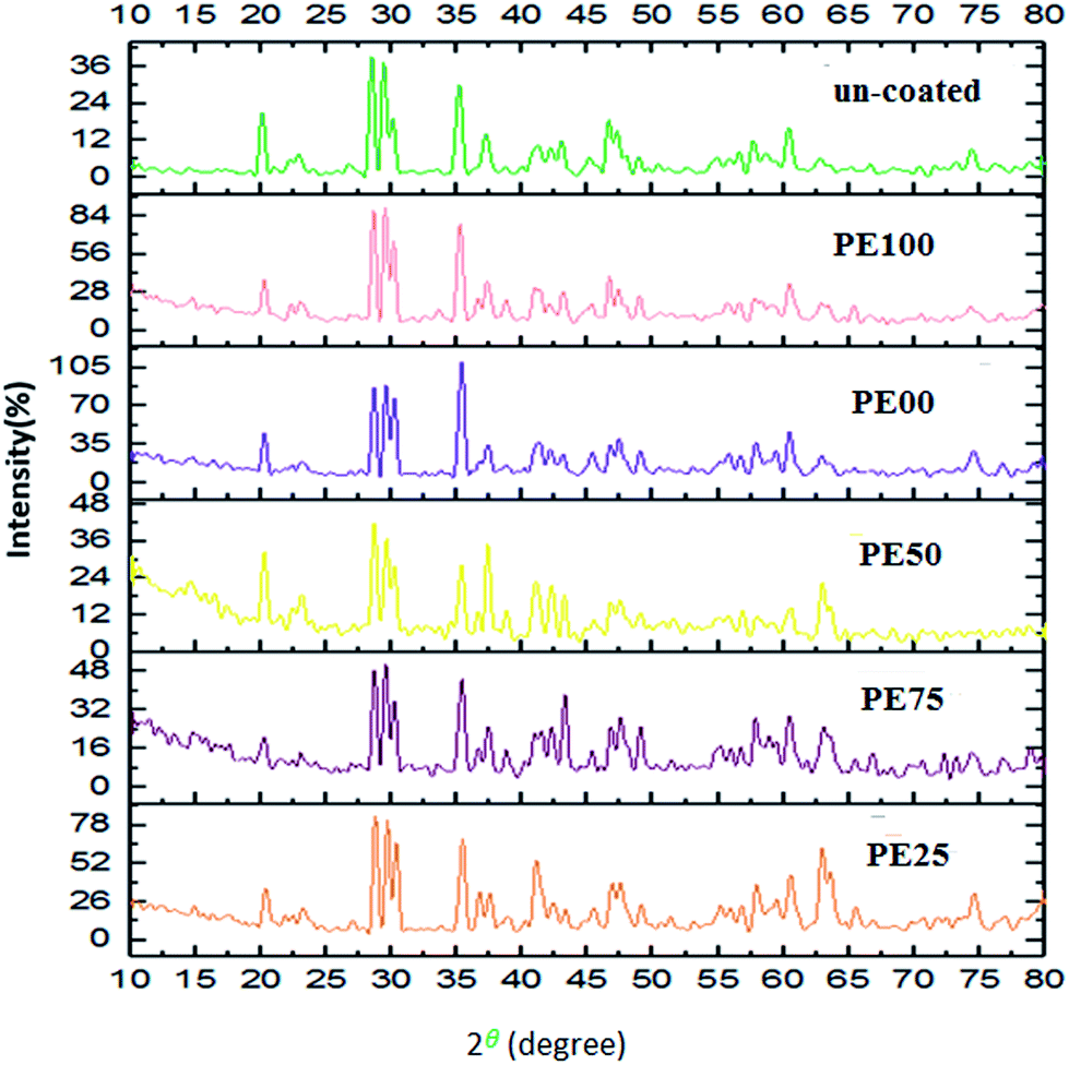
| | Fig. 3 The XRD pattern comparison between un-treated and several SrAl2O4:Eu2+,Dy3+ phosphors treated by PE and PS. | |
 |
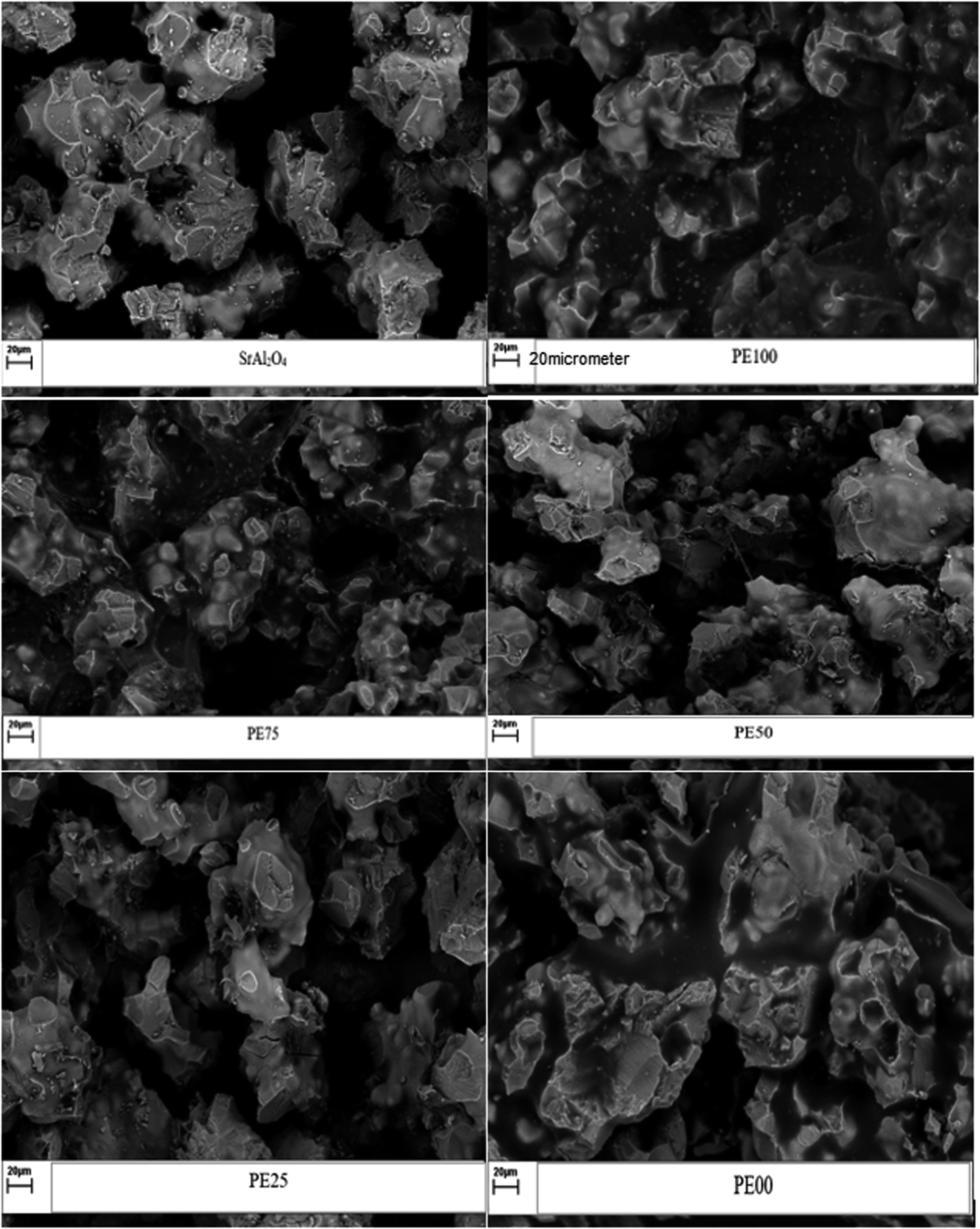
| | Fig. 4 The SEM micrograph comparison between un-treated and several SrAl2O4:Eu2+,Dy3+ phosphors treated by PE and PS. | |
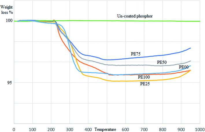 |
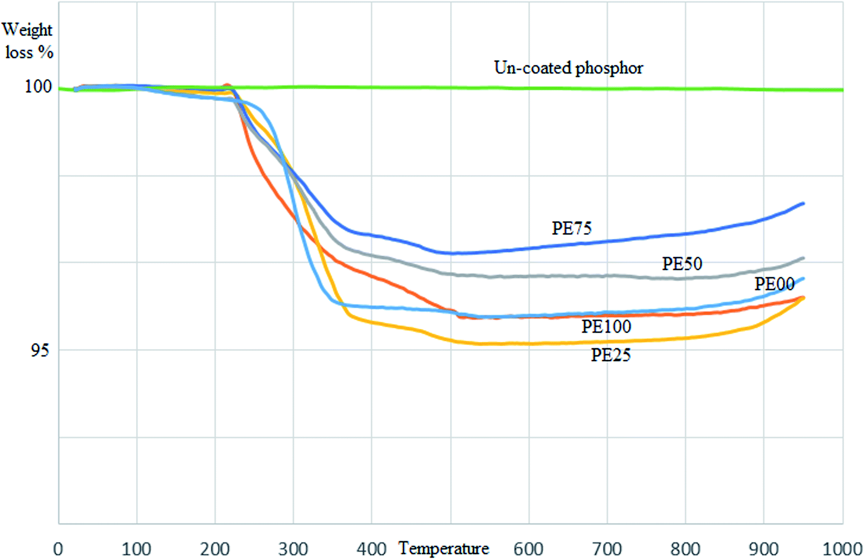
| | Fig. 5 The TGA curve comparison between un-treated and several SrAl2O4:Eu2+,Dy3+ phosphors treated by PE and PS. | |
 |
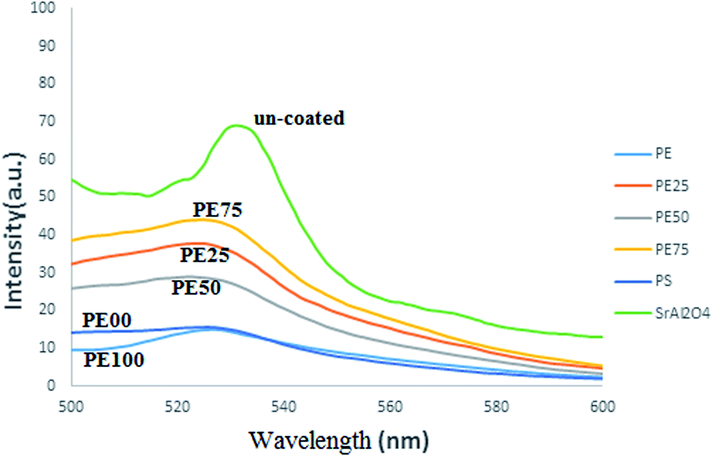
| | Fig. 6 The emission spectra comparison between un-treated and several SrAl2O4:Eu2+,Dy3+ phosphors treated by PE and PS. | |
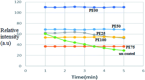 |
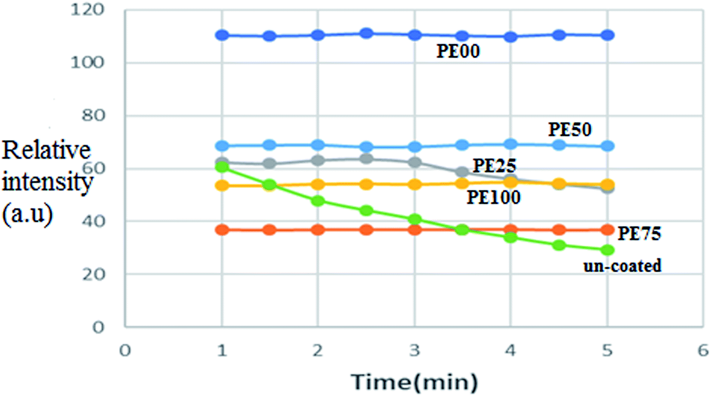
| | Fig. 7 The afterglow brightness decay curve comparison between un-treated and several SrAl2O4:Eu2+,Dy3+ phosphors treated by PE and PS. | |
3. Results and discussion
3.1. Identification and characteristics
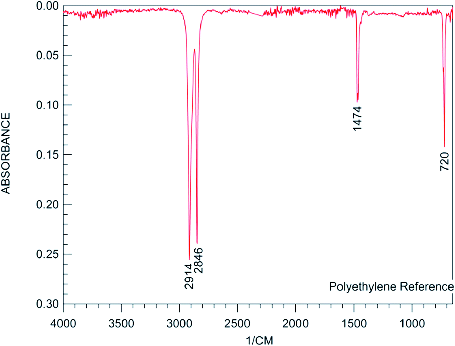
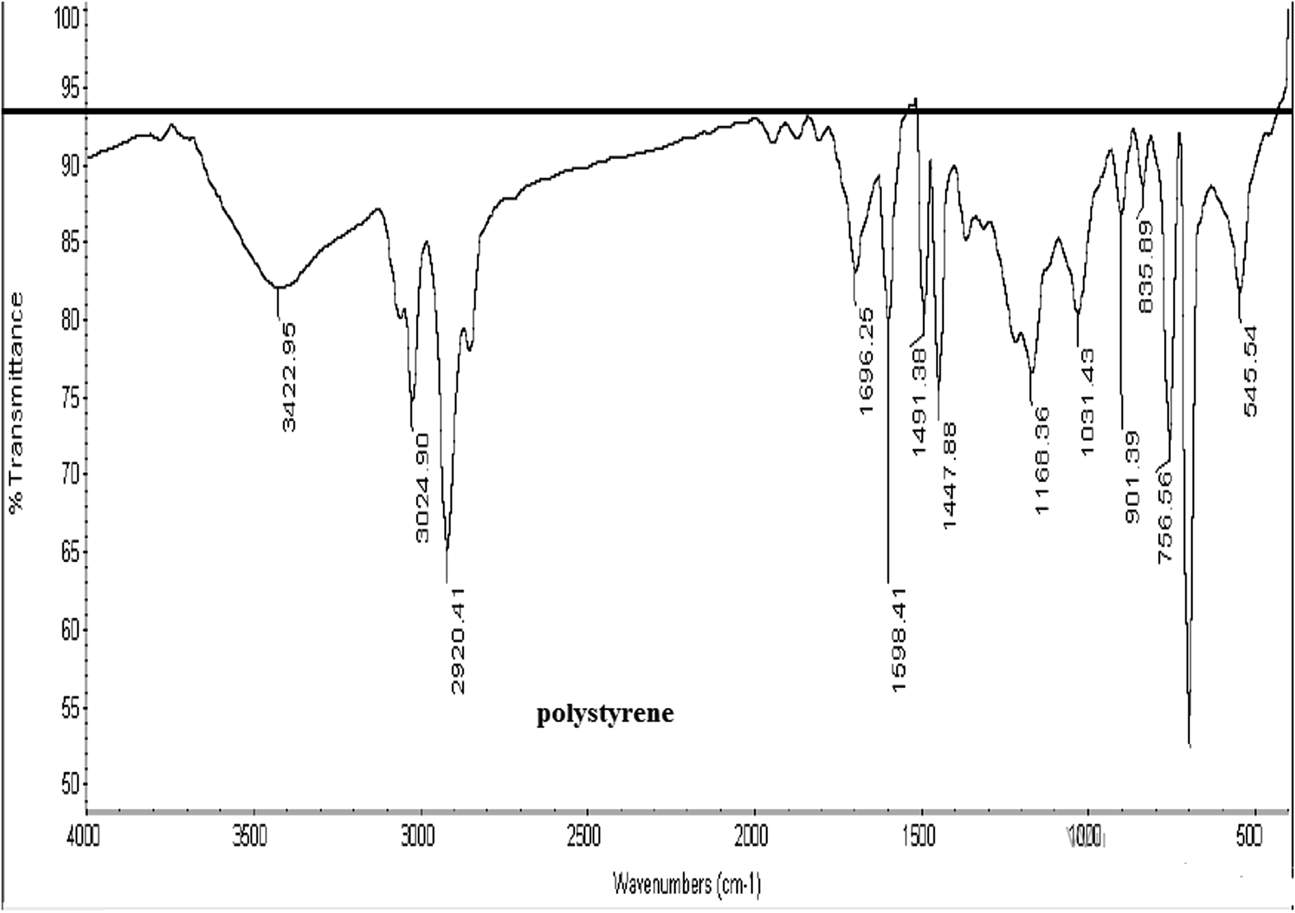
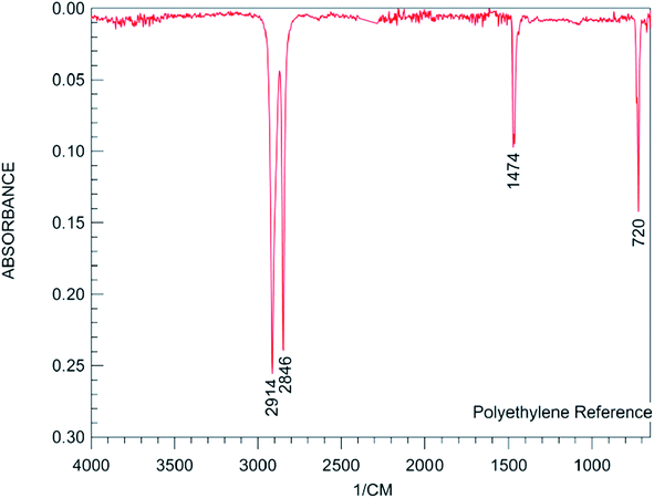
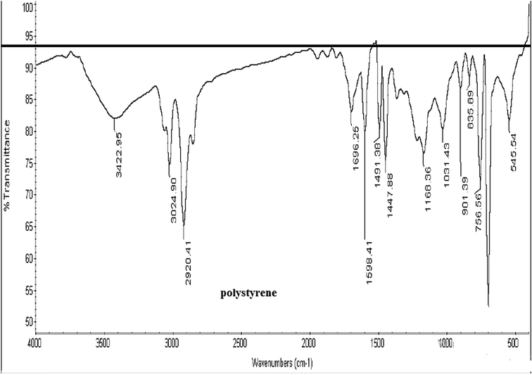
As observed from Fig. 1, the peaks for the uncoated phosphor appearing at 647, 782, 850, 897, 3431 and 445 cm−1 were attributed to the stretching vibrations of the Sr–O, Al–O, Al–O, Al–O, and –OH groups and O–Al–O of SrAl2O4, respectively.42 The intensity of the assigned peak for the –OH group helped evaluate the moisture (water) content of the phosphor. Schemes 1![[thin space (1/6-em)]](https://www.rsc.org/images/entities/char_2009.gif) 43 and 244 represent the typical FT-IR spectra for PE and PS, respectively. As observed from Scheme 1, the peaks at 2850 and 2918, 1470 and 720 cm−1 were attributed to CH2 stretching, bending, and rocking, respectively.43 Fig. 1 shows the aforementioned peaks were appeared in FT-IR spectra of all PE contributed coated samples, PE100, PE75, PE50 and PE25. However these peaks were not appeared for PE00 (coated phosphor with only PS, Table 1) and un-coated samples. Scheme 2 shows that the peak at 3025 cm−1 belongs to alkenyl C–H or stretching of –CH2– and –CH– of the aromatic ring of PS.44 The above-mentioned peak appeared at the same position with different intensities for all PS-coated samples. Considering the small amount of the polymer when compared with the amount of the core phosphor in the treated phosphors, the other peaks seemed to be overlapped by much stronger peaks of the un-coated phosphor in the same areas. The coating of the studied phosphor with PE and PS was more evidenced by the EDS analysis results. Table 2 and Fig. 2 depict the element wt% and the EDS spectra for uncoated and PE and PS-coated SrAl2O4:Eu2+,Dy3+ phosphors, respectively. The uncoated phosphor had 19, 40 and 40% elemental aluminum, oxygen and strontium in the chemical structure, respectively. No elemental carbon was observed in the chemical composition of the above-mentioned phosphor. Meanwhile, for the rest of the treated phosphors with the studied polymers, elemental carbon was observed with different amounts. They were 60, 55, 20, 38 and 34% for the treated phosphors PE100, PE75, PE50, PE25 and PE00, respectively. There was no regular trend for the element content when the PE content in the coating layer was reduced from 100% (pure PE) to 0% (pure PS). However, the most carbon content belonged to PE100 with 60%. This is because the PE macromolecules had higher mobility in the prepared solution when compared with the PS macromolecules. This resulted in the adsorption of the former macromolecules on the phosphor surface with more convenience. Fig. 2 also shows distinguished peaks attributed to carbon, oxygen, aluminum, and strontium near 0.3, 0.5,1.5 and 1.8 keV of different intensities, respectively. As an important conclusion and considering the above-mentioned evidences, the treated phosphor surfaces were properly coated by PE and PS as well as their combination.
43 and 244 represent the typical FT-IR spectra for PE and PS, respectively. As observed from Scheme 1, the peaks at 2850 and 2918, 1470 and 720 cm−1 were attributed to CH2 stretching, bending, and rocking, respectively.43 Fig. 1 shows the aforementioned peaks were appeared in FT-IR spectra of all PE contributed coated samples, PE100, PE75, PE50 and PE25. However these peaks were not appeared for PE00 (coated phosphor with only PS, Table 1) and un-coated samples. Scheme 2 shows that the peak at 3025 cm−1 belongs to alkenyl C–H or stretching of –CH2– and –CH– of the aromatic ring of PS.44 The above-mentioned peak appeared at the same position with different intensities for all PS-coated samples. Considering the small amount of the polymer when compared with the amount of the core phosphor in the treated phosphors, the other peaks seemed to be overlapped by much stronger peaks of the un-coated phosphor in the same areas. The coating of the studied phosphor with PE and PS was more evidenced by the EDS analysis results. Table 2 and Fig. 2 depict the element wt% and the EDS spectra for uncoated and PE and PS-coated SrAl2O4:Eu2+,Dy3+ phosphors, respectively. The uncoated phosphor had 19, 40 and 40% elemental aluminum, oxygen and strontium in the chemical structure, respectively. No elemental carbon was observed in the chemical composition of the above-mentioned phosphor. Meanwhile, for the rest of the treated phosphors with the studied polymers, elemental carbon was observed with different amounts. They were 60, 55, 20, 38 and 34% for the treated phosphors PE100, PE75, PE50, PE25 and PE00, respectively. There was no regular trend for the element content when the PE content in the coating layer was reduced from 100% (pure PE) to 0% (pure PS). However, the most carbon content belonged to PE100 with 60%. This is because the PE macromolecules had higher mobility in the prepared solution when compared with the PS macromolecules. This resulted in the adsorption of the former macromolecules on the phosphor surface with more convenience. Fig. 2 also shows distinguished peaks attributed to carbon, oxygen, aluminum, and strontium near 0.3, 0.5,1.5 and 1.8 keV of different intensities, respectively. As an important conclusion and considering the above-mentioned evidences, the treated phosphor surfaces were properly coated by PE and PS as well as their combination.
 |
| | Scheme 1 A typical FT-IR spectrum for PE.44 | |
 |
| | Scheme 2 A typical FT-IR spectrum for PS.45 | |
Fig. 3 compares the XRD patterns of the uncoated and PE and PS-coated SrAl2O4:Eu2+,Dy3+ phosphors. As observed, the crystalline structure of the SrAl2O4:Eu2+,Dy3+ phosphors was not affected by the polymeric coated layer. In other words, with a precise comparison of the patterns, the reader may find that the main structure of the phosphor did not change, and only the crystallite size of the particles changed during the coating process. Table 3 shows the increase in the average crystallite size (D) of the coated phosphor derived by the Scherrer's equation41 after coating. When the D value for the uncoated phosphor was 14.7 nm, it increased to the values of 19.7, 19.7, 19.6 and 15.3 nm for the coated phosphors PE100, PE75, PE50, and PE25, respectively. There was an exception for PE00 with pure PS in the coating layer. The reason refers to the amorphous state of PS. In fact, PS unlike PE is a known amorphous polymer.
Fig. 4 compares the SEM micrographs of the uncoated and studied PE and PS-coated SrAl2O4:Eu2+,Dy3+ phosphors. As expected,42 Fig. 4 clearly shows sharp and rough edges for the uncoated phosphor because the used phosphor particles were already ground. The aforementioned edges subsequently were covered by a soft and smooth layer of the polymer (Fig. 4).
The thermal stability of the treated phosphors was assessed by TGA analysis. Fig. 5 compares the TGA curves of all the studied phosphors. As observed, the uncoated phosphor was completely stable with negligible weight loss at the swept temperatures of 25–950 °C. However, the coated phosphors missed a part (3.5–5%) of their initial weights between 200 and 500 °C. This is the temperature range of polymer (PE and PS) degradation. The most traditional polymers start degrading when the temperate rises to 200 °C. The surface of the coated phosphors was covered by PE, PS and/or their combinations. Hence, weight loss was predicted during the aforementioned temperatures. The highest and lowest weight loss values were attributed to PE100 and PE75 (4.5 and 2.5%, respectively).
3.2. Afterglow properties and water resistance
Fig. 6 compares the emission spectra of all studied SrAl2O4:Eu2+,Dy3+ phosphors.
For the uncoated phosphor, the maximum intensity was observed at 531 nm because the ratio of Al/Sr in the chemical structure of the phosphor was 2. At this wavelength, the emitted color was green.23 However, the maximum intensity for the coated phosphors was around 528 nm, which showed a negligible difference. Moreover, the intensities of the coated phosphors were lower than that of the uncoated phosphor because the refractive indexes of the used polymers were 1.51 and 1.59 for PE and PS, respectively. These values were lower than the value for the uncoated phosphor. It was predicted that the polymeric coating can reduce the photoluminescence property of the phosphor. In fact, for practical applications, a compromise between two crucial properties, i.e., photoluminescence and water resistance should be reached. Here, although a polymeric coating was not relatively suitable for the former property, it was remarkably beneficial for the latter one.
Fig. 7 depicts the afterglow brightness decay curves for the uncoated and all the studied polymeric coated phosphors PE100, PE75, PE50, PE25, and PE00. As observed, the intensity (brightness) of the uncoated phosphor was reduced by 50% after 5 minutes. Interestingly, with the exception of PE25, the brightness of all the coated phosphors was independent of the time and did not change during the 5 minute period after UV irradiation. This confirmed that the polymeric coating protected the phosphor from hydrolysis as it was predicted that the brightness decay of the SrAl2O4:Eu2+,Dy3+ phosphor refers to the fast hydrolysis of the phosphor.42 The reason was the strong hydrophobic properties of the used polymers PE and PS.
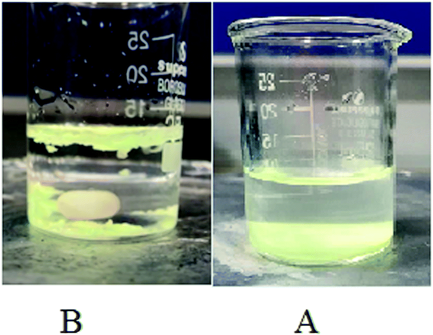
As mentioned, the fast hydrolysis and the subsequent weakness against waterborne media is the major drawback of the SrAl2O4:Eu2+,Dy3+ phosphor. Fig. 8 represents a typical dispersion of the uncoated phosphor (Fig. 8A) and the phosphors coated by the studied polymers PE and PS (Fig. 8B, PE50 in Table 1) in water. As observed, the uncoated phosphor particles partially dispersed in water and the remaining phosphor particles precipitated on the bottom of the beaker. Meanwhile, the coated phosphor particles were not dispersed in water; they agglomerated with each other and most of them floated on the water surface. These observations showed hydrolysis prevention of the phosphor and the consequent pH enhancement of the liquid medium, i.e., water. Consequently, it was good evidence for the improvement of the water resistance property of the phosphor after encapsulation with the studied polymers. It was concluded that the polymeric coated layer protected the phosphor (pigment) from air moisture and water. Our observation was in conformity with another report.45
 |
| | Fig. 8 A typical dispersion of the un-coated phosphor (A) and phosphors coated by the studied polymers PE and PS ((B) PE50 in Table 1) in water. | |
3.3. The apparent photoluminescence appearance
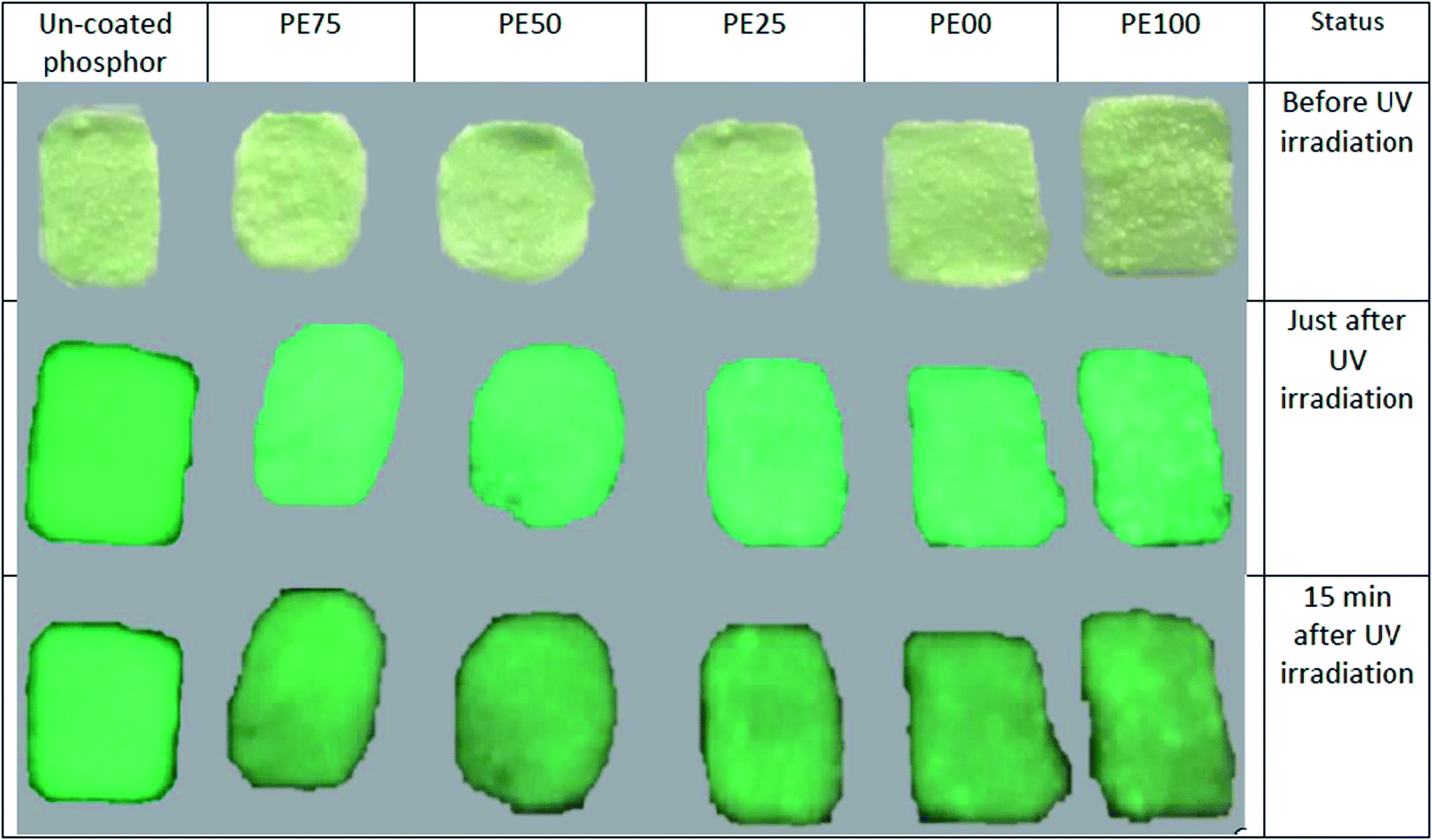
To assess the apparent photoluminescence appearance of the studied phosphors in a real paint, several compositions of the pigment with an acrylic resin were prepared. The procedure has already been explained in detail.42 The resin–phosphor (pigment) weight ratio was 100–30. The prepared paints were irradiated with a UV source at 390 nm for 15 minutes. Fig. 9 compares the photoluminescence of the prepared pigment-acrylic resin compositions before UV irradiation, after UV irradiation, and after aging for 15 minutes. As observed, unlike the uncoated phosphor, the brightness of the coated phosphors changed after aging for 15 minutes sensitively. Beyond this time, the brightness completely disappeared.
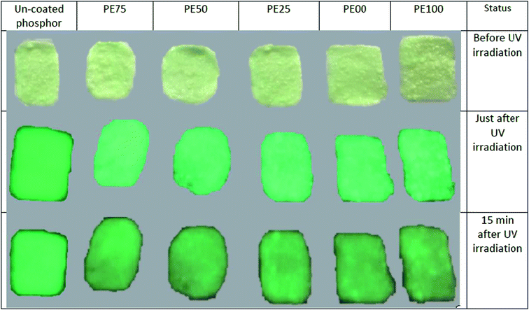 |
| | Fig. 9 The appearances of the added studied pigments to an acrylic resin before UV irradiation, after UV irradiation and after 15 minute aging. | |
3.4. Concluding remarks
From this study, it was revealed that PE and PS individually and in combination were coated on the SrAl2O4:Eu2+,Dy3+ phosphor properly. The EDS spectra showed elemental carbon for the treated phosphors with different amounts. There was no regular trend for element amounts in the composition of the treated phosphors when the PE content in the coating layer was reduced from 100% (pure PE) to 0% (pure PS). Based on the XRD patterns, the crystalline structure of the SrAl2O4:Eu2+,Dy3+ phosphors was not affected by the polymeric coated layer. In the SEM micrographs, the sharp and rough edges of the uncoated phosphor changed to a smooth and soft state for the coated phosphors. The thermal stability of the treated phosphors was lower than that of the uncoated phosphor at high temperatures. The brightness of most of the coated phosphors was independent of the time and did not change during the 5 minute period after UV irradiation. This property makes the polymeric coated phosphors suitable as photoluminescence pigments in all kinds of paints and coatings.
Conflicts of interest
There are no conflicts to declare.
Acknowledgements
The SEM, XRD, FTIR, and photoluminescence (PL) experiments were performed in the Central Laboratory, Faculty of Science and Research Laboratory for Industrial Catalysis and Environment of the Ferdowsi University of Mashhad and Sharif Institute for Nanosciences, respectively. The authors thank the laboratory staff for their sincere cooperation. Approval no. 280.
References
- T. Qi, H. Xia, Z. Zhang, S. Kong, W. Peng, Q. Zhao and Z. Huang, Solid State Sci., 2017, 65, 88–94 CrossRef CAS
 .
. - T. Matsuzawa, Y. Aoki, N. Takeuchi and Y. Murayama, J. Electrochem. Soc., 1996, 143, 2670–2673 CrossRef CAS .
- R. Rojas-Hernandez, F. Rubio-Marcos, M. Angel Rodriguez and J. Francisco Fernandez, Renewable Sustainable Energy Rev., 2018, 81(2), 2759–2770 CrossRef CAS .
- A. Kumar, G. Kedawat, P. Kumar, J. Dwivedi and B. Kumar Gupta, New J. Chem., 2015, 39, 3380–3387 RSC .
- G. Chongfeng, L. Lin, H. Dexiu, S. c. Qiang and L. Yuhua, Mater. Chem. Phys., 2007, 106, 268–272 CrossRef .
- Y. Imai, R. Momoda, Y. Adachi, K. Nishikubo and Y. Kaida, J. Electrochem. Soc., 2007, 154(3), 77–80 CrossRef .
- R. Li, J. Ye, J. Wang, X. Lu, Y. Lin and G. Ning, Adv. Mater. Res., 2009, 58, 199–204 CAS .
- Q. Yang, Y. Liu, C. Yu, G. Zhu, L. Sha, Y. Yang, M. Zheng and B. Lei, Appl. Surf. Sci., 2012, 258, 6814–6818 CrossRef .
- Sh. Yu, P. Pi, X. Wen, J. Cheng and Z. Yang, Can. J. Chem. Eng., 2008, 86, 30–34 CrossRef CAS .
- X. Lü, M. Zhong, W. Shu, Q. Yu, X. Xiong and R. Wang, Powder Technol., 2007, 177, 83–86 CrossRef .
- X. Lu, Mater. Chem. Phys., 2005, 93, 526–530 CrossRef .
- Y. Zhu, J. Zeng, W. Li, L. Xu, Q. Guan and Y. Liu, Appl. Surf. Sci., 2009, 255, 7580–7585 CrossRef CAS .
- H. N. Luitel, T. Watari, T. Torikai, M. Yada, R. Chand, C. N. Xu and K. Nanoka, Appl. Surf. Sci., 2010, 256, 2347–2352 CrossRef CAS .
- S. Tian, J. Wen, H. Fan, Y. Chen, J. Yan and P. Zhang, Polym. Int., 2016, 65, 1238–1244 CrossRef CAS .
- H. Wanga, X. Liangb, K. Liu, Q. Zhou, J. Wang, P. Chen, B. He and J. Li, Key Eng. Mater., 2016, 680, 224–227 Search PubMed .
- T. Mayer, S. A. Yamanaka and J. Zieba, Color-shifting pigments and foils with luminescent coatings, US pat. 6565770B1, 2003 .
- S. Wu, Z. Pan, R. Chen and X. Liu, Springer Briefs in Materials, Springer Nature Switzerland AG, 2017 Search PubMed .
- S. B. Mishra, A. K. Mishra, A. S. Luyt, N. Revaprasadu, K. T. Hillie, W. J. vdM Steyn, E. Coetssee and H. C. Swart, J. Appl. Polym. Sci., 2010, 115, 579–587 CrossRef CAS .
- S. B. Mishra, A. K. Mishra, N. Revaprasadu, K. T. Hillie, W. J. vdM Steyn, E. Coetssee and H. C. Swart, J. Appl. Polym. Sci., 2009, 112, 3347–3354 CrossRef CAS .
- L. Peng, Y. Luo, Y. Dan, L. Zhang, Q. Zhang, Sh. Xia and X. Zhang, Colloid Polym. Sci., 2006, 285, 153–160 CrossRef CAS .
- X. Lü, X. Liu and G. Gai, Adv. Mater. Res., 2009, 58, 169–175 Search PubMed .
- J. Chang, S. Wu and Sh. Zhang, Adv. Mater. Res., 2013, 634–638, 2314–2317 Search PubMed .
- M. P. Anesh, K. H. Gulrez, A. Anis, H. Shaikh, M. E. Ali Mohsin and S. M. Al-Zahrani, Adv. Polym. Technol., 2014, 33(S1), 21436–21445 CrossRef .
- H. Du, W. Shan, L. Wang, D. Xua, H. Yin, Y. Chen and D. Guo, J. Lumin., 2016, 176, 272–277 CrossRef CAS .
- B. Zhai and Y. M. Huanga, Key Eng. Mater., 2013, 538, 197–200 Search PubMed .
- Q. Yu, Y. Wang, R. Mei, Y. Yin, J. You and L. Chen, Anal. Chem., 2019, 91(8), 5270–5277 CrossRef CAS PubMed .
- S. Lee and J. W. Park, Sens. Actuators, B, 2017, 249, 364–377 CrossRef CAS .
- J. B. Qi, Y. L. Xu, Y. Liu, Y. Wang, Y. Sui, J. G. Liu and X. Wang, Colloids Surf., B, 2017, 152, 475–481 CrossRef .
- X. Wang, J. Yu, X. Wu, J. Fu, Q. Kang, D. Shen, J. Li and L. Chen, Biosens. Bioelectron., 2016, 81, 438–444 CrossRef CAS PubMed .
- Zh. Zhang, Zh. Chen, Sh. Wang, F. Cheng and L. Chen, ACS Appl. Mater. Interfaces, 2015, 7(50), 27639–27645 CrossRef CAS PubMed .
- W. Cui, R. Liu, E. Manna, J. K. Park, F. Fungura, J. Shinar and R. Shinar, Anal. Chim. Acta, 2015, 853, 563–571 CrossRef CAS PubMed .
- Y. J. Hsu and S. Y. Lu, Chem. Commun., 2004, 18, 2102–2103 RSC .
- Y. J. Hsu and S. Y. Lu, Langmuir, 2004, 20, 23–26 CrossRef CAS PubMed .
- Y. J. Hsu and S. Y. Lu, Langmuir, 2004, 20, 194–201 CrossRef CAS PubMed .
- Y. J. Hsu, S. Y. Lu and Y. F. Lin, Adv. Funct. Mater., 2005, 15, 1350–1357 CrossRef CAS .
- Y. J. Hsu and Sh. Y. Lu, Appl. Phys. A, 2005, 81, 573–578 CrossRef CAS .
- Y. -J. Hsu and S. -Y. Lu, Small, 2008, 4(7), 951–955 CrossRef CAS PubMed .
- W. Y. Cheng, W. T. Chen, Y. J. Hsu and Sh. Y. Lu, J. Phys. Chem. C, 2009, 113(40), 17342–17346 CrossRef CAS .
- B. C. Fitzmorris, Y. C. Pu, J. K. Cooper, Y. F. Lin, Y. J. Hsu, Y. Li and J. Z. Zhang, ACS Appl. Mater. Interfaces, 2013, 5(8), 2893–2900 CrossRef CAS PubMed .
- Y. C. Pu and Y. j. Hsu, Nanoscale, 2014, 6, 3881–3888 RSC .
- H. P. Klug and L. E. Alexander, X-ray diffraction procedures for polycrystalline and amorphous materials, Wiley, New York, 1974 Search PubMed .
- F. Jaberi, S. Ostad Movahed and A. Ahmadpour, J. Fluoresc., 2019, 29(2), 461–471 CrossRef CAS PubMed .
- M. Jordi, Case Study, FTIR for Identification of Contamination, Jordi Labs LLC, USA, 2015 Search PubMed .
- M. Fathyzl, T. A. Moghny, A. E. A. Allah and A. H. A. A. El-Bellihi, Elixir Social Studies, 2013, 60, 16095–16097 Search PubMed .
- J. Lin, Y. Huang, J. Zhang, F. Shi, S. Wei, J. Gao, Z. Huang, X. Ding and C. Tang, Mater. Chem. Phys., 2008, 108, 440–444 CrossRef CAS .
|
| This journal is © The Royal Society of Chemistry 2019 |
Click here to see how this site uses Cookies. View our privacy policy here. 
 Open Access Article
 This Open Access Article is licensed under a Creative Commons Attribution-Non Commercial 3.0 Unported Licence
 *b and
Ali Ahmadpour
*b and
Ali Ahmadpour