DOI:
10.1039/C9RA08561K
(Paper)
RSC Adv., 2019,
9, 40024-40030
Effects of size on the photocatalytic properties of high-index faceted pseudocubic and rhombohedral α-Fe2O3 nanocrystals†
Received
19th October 2019
, Accepted 28th November 2019
First published on 4th December 2019
Abstract
Size-controlled and high-index faceted α-Fe2O3 nanocrystals with pseudocubic and rhombohedral morphologies were synthesized through the hydrothermal treatment of β-FeOOH at different pHs. The size effect on the photocatalytic oxygen evolution efficiency of high-index faceted α-Fe2O3 nanocrystals was investigated. Rhombohedral α-Fe2O3 (pH 6.0) exhibits an outstanding apparent quantum yield of 9.93% and an oxygen evolution efficiency of 20.3%, which can be attributed to the optimal size and high-indexed {104} planes. This work provides a new idea for the design of high activity water oxidation catalysts, through the size optimization of high-index faceted materials.
Introduction
Given the growing energy consumption and environmental pollution caused by fossil fuel combustion, one of the biggest challenges of this century is the search for clean and renewable energy sources.1 Currently, the direct conversion of solar energy into chemical energy by photocatalytic water splitting has aroused widespread interest. Nonetheless, in the water splitting context, the water oxidation reaction has to overcome higher energy barriers, and is thought to be the bottleneck of water splitting.2 Thus, much effort has been devoted to the design and construction of highly efficient water oxidation catalysts (WOCs). Although IrO2 and RuO2 are considered to be the most efficient catalysts for water oxidation,3,4 their extremely high cost makes researchers turn their research enthusiasm to cheap transition metal catalysts. A large number of transition metal compounds, including Co,5,6 Cu,7 Mn,8–10 W,11–13 and Fe,14–16 have been explored as WOCs. Among these compounds, iron-based WOCs have attracted much attention due to their low cost and low toxicity.17,18
α-Fe2O3, because of its proper bandgap, has been extensively utilized as the photocatalyst or cocatalyst for oxygen evolution,19 hydrogen evolution,20 CO2 reduction,21 and pollutant degradation.22–24 Considerable effort has been devoted to improving the photocatalytic oxygen evolution of α-Fe2O3 based on the heterojunction construction.25–30 The composite structure of α-Fe2O3/rGO significantly improves the charge carries separation of α-Fe2O3 and enhances the photocatalytic water oxidation performance.28 The tight hetero-junction structure of α-Fe2O3/g-C3N4 has been demonstrated as active sites for visible-light-driven oxygen generation.25 The optimized integration of cocatalyst CoOx enables hexagonal α-Fe2O3 nanoplates with dramatically enhanced O2 evolution rate.26 The Pt nanoparticles decorated α-Fe2O3 nanoplates structure exhibit the enhanced photoactivity and photostability for water oxidation.27 Besides, the fabrication of α-Fe2O3 nanocrystals with specific shapes and sizes is also conducive to enhance the photocatalytic oxygen evolution ability. Moreover, the shape effect is essentially due to the arrangement of atoms on different exposed crystal faces. Plenty of work has confirmed that the {012} and {104} planes of α-Fe2O3 are high-index planes.31–34 Ma et al. found that the exposed {104} planes of α-Fe2O3 exhibits excellent gas sensing properties.33 Zhao et al. investigated that α-Fe2O3 nanocubes exposed {012} active facets combination with graphene lead to boosted lithium storage capability.34 Recently, Xiang and co-workers reported that α-Fe2O3 nanocubes with {012} facets have much higher photocatalytic water oxidation activity than α-Fe2O3 nanoflakes with {001} facets.31 Wang et al. researched that α-Fe2O3 enclosed by {012} and {104} facets can facilitate to increase the activity of photocatalytic oxygen evolution significantly.32 However, the size effect on the photocatalytic water oxidation performance of α-Fe2O3 nanocrystals has been scarcely investigated. Moreover, the attempt to combine the size effect with the high-index facet to improve the photocatalytic activity of α-Fe2O3 is significant.
Here, we selectively synthesized pseudocubic and rhombohedral α-Fe2O3 nanocrystals with varying sizes through the hydrothermal treatment of the β-FeOOH precursor at different pH values. By adjusting the pH value of the precursor, a morphology evolution of α-Fe2O3 nanocrystals from {012} pseudocubes to {104} rhombohedrons was observed with the reduction in size. Through a comprehensive investigation of the factors affecting the oxygen production performance of the catalyst, we confirm the size-dependent photocatalytic water oxidation property of α-Fe2O3. Moreover, we obtained {104} planes faceted Fe2O3 (pH 6.0) possessing excellent photocatalytic oxygen evolution performance.
Experimental
Materials
Ferric chloride hexahydrate (FeCl3·6H2O), sodium hydroxide (NaOH) were purchased from Tianjin Zhiyuan Chemical Reagent Co., Ltd. All chemicals were of analytical grade and used directly without further purification.
Fabrication of α-Fe2O3 nanocrystals
The synthesis route was carried out according to the literature with a slight modification.35 When synthesizing α-Fe2O3, 0.024 mol FeCl3·6H2O was dissolved in 600 mL deionized water, refluxed and stirred at 78 °C for 12 h to obtain a brown β-FeOOH solution with an initial pH value of 1.2 (measured by a LICHEN pH meter). The solution was divided into four equal portions, and the pH value of each portion was tuned with NaOH (1 mol L−1) aqueous solution to 1.2, 2.0, 4.0, and 6.0, respectively. Subsequently, four 1 L Teflon autoclaves were used to encapsulate the β-FeOOH solutions with different pHs, which were then heated to 150 °C for 10 h. After natural cooling to room temperature, it was washed with ethanol and water several times and dried at 40 °C. The final products were labeled as Fe2O3-1.2, Fe2O3-2.0, Fe2O3-4.0, and Fe2O3-6.0, respectively.
Characterizations
The crystalline phase of the as-synthesized products was identified by X-ray diffraction (XRD) (BRUKER D8 Advance) at a scanning rate of 5° min−1 in 2θ ranging from 10° to 80°. A Hitachi S-4800 scanning electron microscope was used to obtain the scanning electron microscopy (SEM) images at 5 kV. The transmission electron microscopy (TEM) images were obtained on an FEI Tecnai G2 f20 s-twin with an accelerating voltage of 200 kV. The UV-vis absorption spectra of as-obtained catalysts were obtained by a Hitachi U-3010 spectrophotometer. The Brunauer–Emmett–Teller (BET) surface areas of the products were evaluated by N2 adsorption–desorption measurements at 77 K (liquid nitrogen) in an automated surface area and porosity analyzer (ASAP2020, Micromeritics, USA). Photoluminescence spectra (PL) of the catalysts were characterized with a fluorescence spectrophotometer (Hitachi-F-4500) with an exciting wavelength of 300 nm. The particle size distribution was measured by Nanomeasure software.
Photocatalytic oxygen evolution measurements
Photocatalytic water oxidation tests were performed in a buffer solution with an argon atmosphere at room temperature. In this experiment, 5.0 mg of α-Fe2O3 was dispersed in a 10.0 mL 80.0 mM sodium borate buffer solution containing 1.0 mM [Ru(bpy)3](ClO4)2 and 20.0 mM Na2S2O8, and sealed with a rubber gasket in a 20 mL round-bottom flask. The solution was to degas the air with argon and then irradiated it with visible light (300 W Xe lamp, λ > 420 nm) at room temperature. Every two minutes, O2 in the top air was sampled with a 100 μL syringe and analyzed by GC-TCD equipped with a 5 Å molecular sieve column.
Photoelectrochemical measurements
The transient photocurrent response was performed on a Chi 660D electrochemical workstation using a standard three-electrode system with Ag/AgCl and Pt electrodes as the counter and reference electrodes, respectively. The working electrode was prepared as follows: 5.0 mg of the as-synthesized sample was mixed with 1.0 mL of deionized water by ultrasonic treatment. Then, the mixture was coated on a 2.5 cm × 1.5 cm F-doped SnO2-coated glass (FTO glass) electrode with approximately uniform thickness. Subsequently, the electrode was dried in vacuum at 110 °C for 10 h, and 0.5 mM Na2S2O4 aqueous solution was used as the electrolyte.
Results and discussion
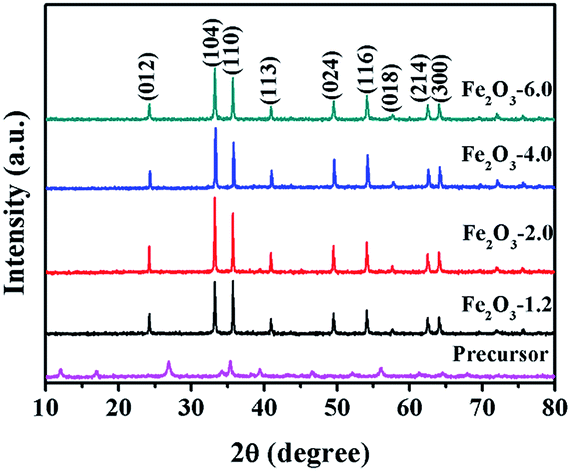
Fig. 1 exhibits the XRD patterns of the precursor and products. All products have obvious diffraction peaks at 2θ = 24.26°, 33.22°, 35.73°, 40.95°, 43.65°, 49.54°, 54.10°, 57.61°, 62.50°, and 64.07° could be indexed to the (012), (104), (110), (113), (024), (116), (018), (214), and (300) crystal planes, corresponding to the hexagonal hematite (JCPDS no. 33-0664). This result indicates that precursor β-FeOOH (JCPDS no. 34-1266) was completely transformed into to α-Fe2O3 through the hydrothermal treatment under different initial pHs.36 The average crystallite sizes of α-Fe2O3 nanocrystals prepared at pH values of 1.2, 2.0, 4.0, and 6.0 were 50.61, 42.92, 39.99, and 37.06 nm, respectively, which were calculated by Scherrer formula.37 The result demonstrates the crystallite size of the sample decrease with the increasing of precursor pH value.
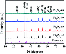 |
| | Fig. 1 XRD patterns of the precursor and samples Fe2O3-x (x is 1.2, 2.0, 4.0, and 6.0). | |
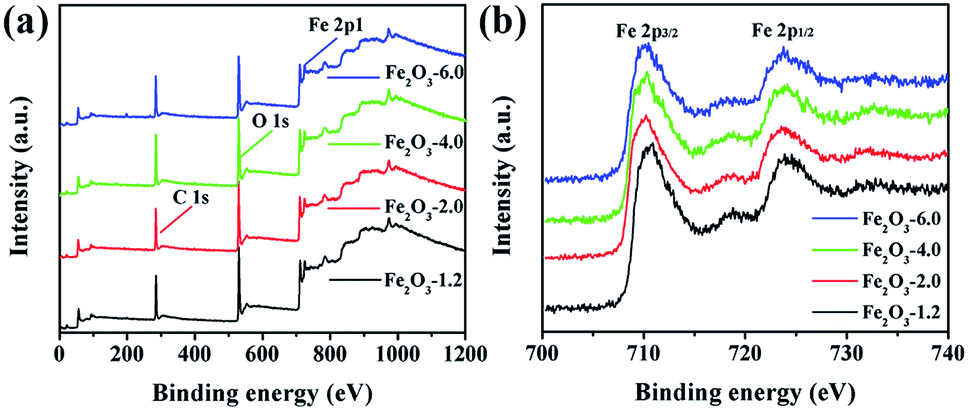
For further identifying the samples, the surface composition of the products was analyzed by XPS in Fig. 2. The XPS spectra of the samples display the same line shape, and the presence of Fe, O, and C elements in Fig. 2a demonstrates that the four substances have the same valence state of elements. The binding energy peaks at 710.3 and 723.8 eV in the Fe 2p high-resolution XPS spectrum (Fig. 2b) are attributed to Fe 2p3/2 and Fe 2p1/2, respectively, which strongly proves that Fe element in iron oxide exists in the form of the Fe3+. The lineshape and binding energies of Fe 2p agree well with those reported in the literature.38
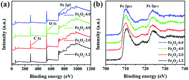 |
| | Fig. 2 XPS spectra of α-Fe2O3 nanocrystals: (a) full survey spectrum of Fe2O3-x (x is 1.2, 2.0, 4.0, and 6.0); (b) Fe 2p peaks of Fe2O3-x. | |
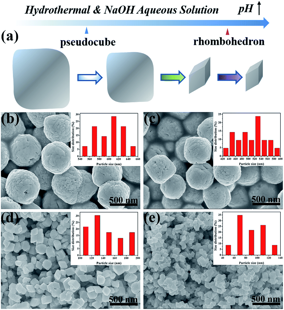
The size and morphology of the α-Fe2O3 nanocrystals were characterized by SEM in Fig. 3. The schematic illustration in Fig. 3a shows the morphology and size evolution of α-Fe2O3 nanocrystals with varying pH values. Fig. 3b and c exhibit the products of Fe2O3-1.2 and Fe2O3-2.0 have the same pseudocubic morphology and different mean lengths of ca. 603 and 507 nm, respectively. Moreover, rhombohedral α-Fe2O3 with different average sizes of ca. 145 and 88 nm were obtained at pH 4.0 and 6.0, respectively (Fig. 3d and e). It is worth mentioning that the rough surface of pseudocubes mirrors the growth nature of the iron oxide, which is formed by the aggregation and fusion of plenty of small particles. The crystal growth behavior at the expense of small particles is consistent with the description of the Ostwald ripening mechanism.39 Hence, the Ostwald ripening mechanism could be used to explain α-Fe2O3 growth behavior. Overall, the pH control process discloses that increasing the precursor pH not only contributes to the formation of smaller α-Fe2O3 nanocrystals but also driving the shape transformation of α-Fe2O3 from pseudocubic to rhombohedron.
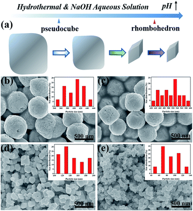 |
| | Fig. 3 (a) Schematic illustration of the growth of α-Fe2O3 with pH change; (b–e) SEM images of the samples and inset of corresponding particle size distribution, (b) Fe2O3-1.2, (c) Fe2O3-2.0, (d) Fe2O3-4.0, and (e) Fe2O3-6.0. | |
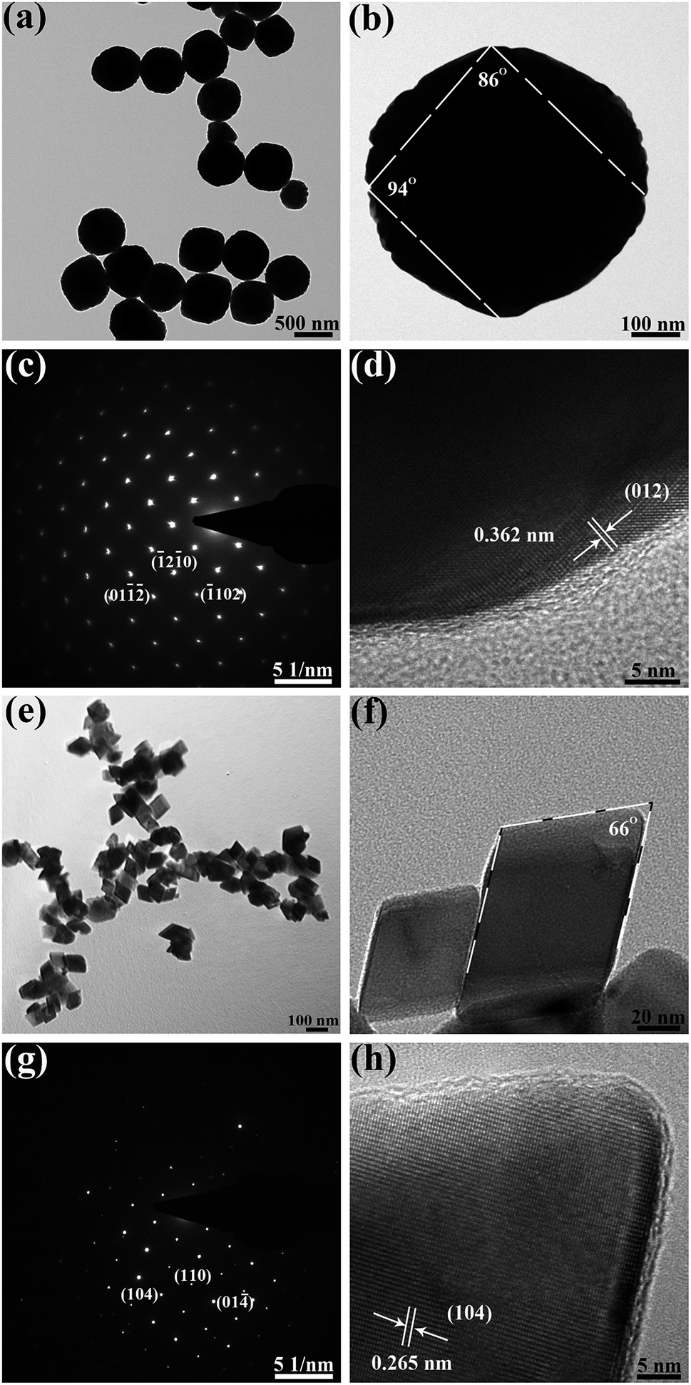
High-resolution transmission electron microscopy (HRTEM) was employed to recognize the dominant active crystal planes of the two typical samples Fe2O3-1.2 and Fe2O3-6.0. TEM images and selected area electron diffraction (SAED) pattern of the pseudocubic α-Fe2O3 (pH 1.2) are exhibited in Fig. 4a–d. Pseudocubic exhibits rhombus facets with dihedral angles between two adjacent facets are 86° and 94° (Fig. 4b). The ordered diffraction spots in the SEAD pattern (Fig. 4c) present the single-crystalline structure of the pseudocubes. Further, the HRTEM shows the measured lattice spacing of the exposed facet is 0.362 nm (Fig. 4d), corresponding to the (012) facet of α-Fe2O3. The above characteristics are consistent with the single-crystal α-Fe2O3 pseudocubes enclosed by {012} planes reported in the literature.40,41 Fig. 4e–g exhibits the TEM images and SAED pattern of the rhombohedral α-Fe2O3 (pH 6.0). TEM images in Fig. 4e and g reveal that the nanocrystals are α-Fe2O3 rhombohedrons with a single-crystalline structure. The measured lattice fringe (Fig. 4h) is of 0.265 nm, agree well with (104) plane of α-Fe2O3. The dihedral angle measured in Fig. 4f is 66°, which can match with the theoretical value of 64.9°.42 These descriptions of α-Fe2O3 (pH 6.0) are in agreement with the characteristics of rhombohedral iron oxide enclosed by {104} planes.43
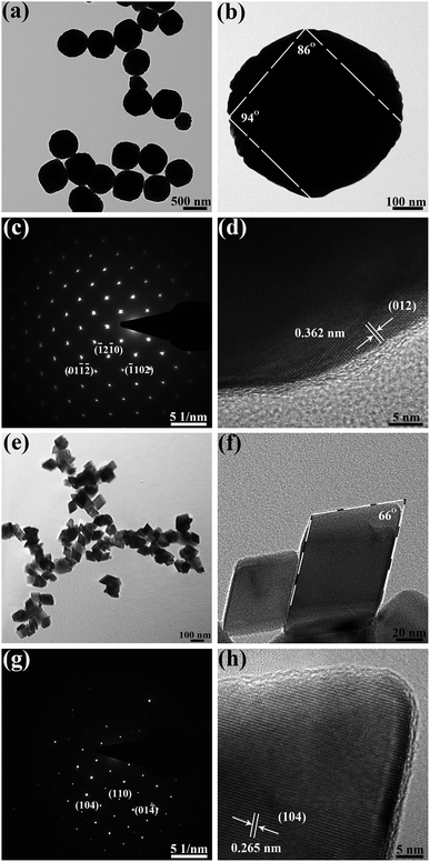 |
| | Fig. 4 (a, b) and (e, f) TEM, (c) and (g) SAED, (d) and (h) HRTEM images of pseudocubic α-Fe2O3 (pH 1.2) and rhombohedral α-Fe2O3 (pH 6.0), respectively. | |
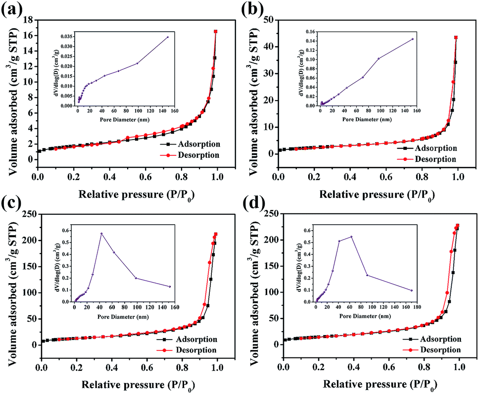
Brunauer–Emmett–Teller (BET) adsorption/desorption isotherms and Barrett–Joyner–Halenda (BJH) pore size were used to characterize the surface properties of the catalysts (Fig. 5). Each isotherm corresponds to a type IV isotherm with a small hysteresis loop, indicating the presence of mesopores in the catalyst. The pore size distribution curves of four α-Fe2O3 samples show that the pore size distribution ranges from 1.7 to 170 nm, which confirms the existence of mesopores and macropores. The specific surface areas (Table 1) of catalysts calculated by the BET method are 6.29, 8.93, 47.03, and 52.70 m2 g−1 corresponding to Fe2O3-1.2, Fe2O3-2.0, Fe2O3-4.0, and Fe2O3-6.0, respectively.
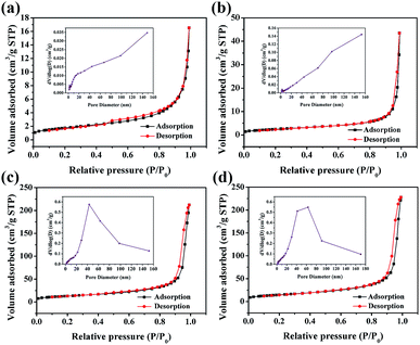 |
| | Fig. 5 N2 adsorption–desorption isotherm of sample (inset of Barrett–Joyner–Halenda pore size), (a) Fe2O3-1.2, (b) Fe2O3-2.0, (c) Fe2O3-4.0, and (d) Fe2O3-6.0. | |
Table 1 Physicochemical properties and oxygen evolution activities of α-Fe2O3 samples
| Catalysts |
Morphology |
Dominant facets |
Specific surface area (m2 g−1) |
O2 evolution (μmol) |
| Fe2O3-1.2 |
Pseudocubic |
{012} |
6.29 |
2.71 |
| Fe2O3-2.0 |
Pseudocubic |
— |
8.93 |
3.28 |
| Fe2O3-4.0 |
Rhombohedron |
— |
47.03 |
16.28 |
| Fe2O3-6.0 |
Rhombohedron |
{104} |
52.70 |
20.32 |
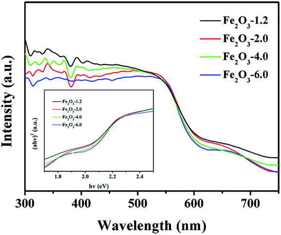
UV-vis diffuse reflectance spectra (Fig. 6) show that the absorption edges of all samples are longer than 600 nm, which reflects the strong visible-light-harvesting ability of samples. Moreover, the absorption band edge of the product is blue-shifted with an increase of the pH value, which could result from the quantum size effect.44 The bandgap of samples was determined from the Tauc plot (inset of Fig. 6), claiming the indirect bandgap of samples is 1.870, 1.885, 1.925, and 1.964 eV, respectively. Combined with Mulliken electronegativity theory (ECB = X − EC − 1/2Eg, EVB = ECB + Eg, where X is absolute electronegativity, EC is the energy of free electrons, EVB is the potential of the conduction band, and EVB is the potential of the valence band),45 the EVB and ECB of the four samples are determined. As seen in Fig. 7, the valence bands of the semiconductors are greater than 1.23 V, which meets the requirement of oxygen evolution kinetics. Moreover, the valence band becomes more positive with the increase of pH value, implying the enhance of water oxidation ability.
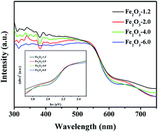 |
| | Fig. 6 UV-visible diffuse reflectance spectra of Fe2O3-x (inset of Tauc plots). | |
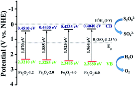 |
| | Fig. 7 Schematic drawing of redox potentials of Fe2O3-x. | |
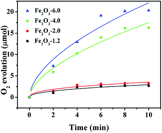
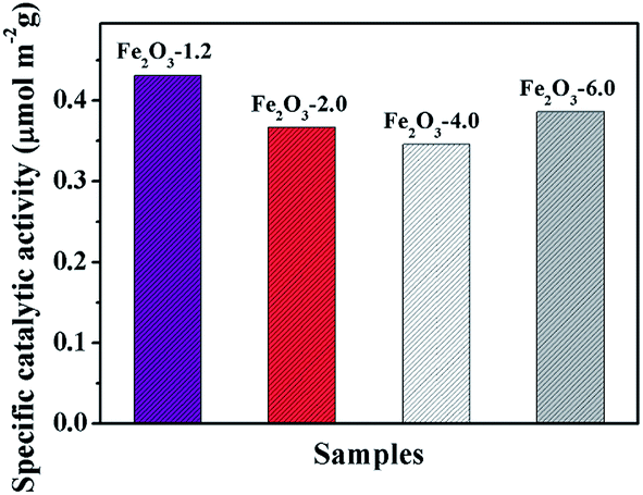
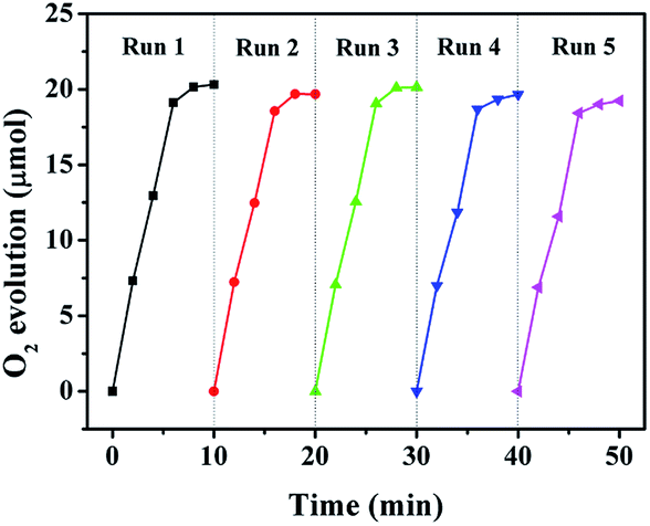
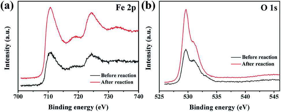
The curves in Fig. 8 display the amount of oxygen evolution of the four α-Fe2O3 samples follows the order of Fe2O3-6.0 > Fe2O3-4.0 > Fe2O3-2.0 > Fe2O3-1.2. In particular, Fe2O3-6.0 possesses the maximum oxygen evolution of 20.32 μmol, almost 7.5 times that of Fe2O3-1.2 (2.71 μmol). In order to comprehensively analyze the influence of size and crystal surface factors on the oxygen production performance of the catalysts, we calculated the specific activity of the four samples. It can be seen intuitively that the specific activity of the four samples has not much difference (Fig. 9), especially the difference between Fe2O3-6.0 and Fe2O3-1.2 can almost be seen as a deviation. This result reflects size effect is the primary factor, which determines the oxygen evolution efficiency of {104} planes faceted Fe2O3-6.0 superior to that of other catalysts. Moreover, compared with other iron-based catalysts (Table 2), Fe2O3-6.0 has an outstanding apparent quantum yield of 9.93% and an oxygen evolution efficiency of 20.3%, which could be ascribed to the optimal size and high-activity planes. After five times of oxygen evolution performance test (Fig. 10), the oxygen evolution did not decrease obviously, indicating Fe2O3-6.0 has excellent cycle stability. We further analyzed the valence states and surface properties of the sample Fe2O3-6.0 before and after the photocatalytic reaction by XPS. Fig. 11a and (b) show the high-resolution XPS spectra of Fe 2p and O 1s before and after the reaction. The binding energy of each element has not changed. Therefore, we conclude that the superior performance stability can be ascribed to the stable structure.
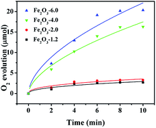 |
| | Fig. 8 Plots of oxygen evolution vs. time for visible-light-driven water oxidation by α-Fe2O3 nanocrystals. Condition: 5.0 mg catalyst, Xe lamp, 300 W, λ > 420 nm, 100 mW cm−2, 10 min lumination, 1.0 mM [Ru(bpy)3](ClO4)2, 20.0 mM Na2S2O8, 80.0 mM sodium borate buffer (initial pH 9.0). | |
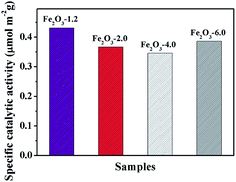 |
| | Fig. 9 Specific catalytic activities (the amount of O2 per unit surface area) of α-Fe2O3 samples. | |
Table 2 Comparison of catalytic performance of different catalysts
| Catalysts |
O2 (μmol) |
O2 yielda (%) |
Reference |
| Yield is defined as twice the number of moles of O2 per mole of Na2S2O8. |
| Fe2C |
10.32 |
20.64 |
49 |
| Fe2O3 |
2.83 |
17.7 |
31 |
| Fe2O3-6.0 |
20.32 |
20.32 |
This work |
| Fe2O3-4.0 |
16.28 |
16.28 |
This work |
| Fe2O3-2.0 |
3.28 |
3.28 |
This work |
| Fe2O3-1.2 |
2.71 |
2.71 |
This work |
| FeOOH |
7.91 |
3.955 |
50 |
| NiFe2O4 |
3.7 |
7.40 |
51 |
 |
| | Fig. 10 Photostability study of Fe2O3-6.0 in the water oxidation reaction. Condition: 5.0 mg catalyst, Xe lamp, 300 W, λ > 420 nm, 100 mW cm−2, 1.0 mM [Ru(bpy)3](ClO4)2, 20.0 mM Na2S2O8, 80.0 mM sodium borate buffer (initial pH 9.0). | |
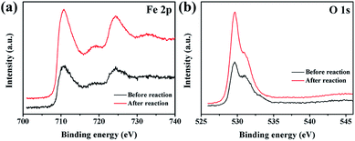 |
| | Fig. 11 XPS spectra of Fe2O3-6.0 before and after photocatalytic reaction, Fe 2p (a) and O 1s (b). | |
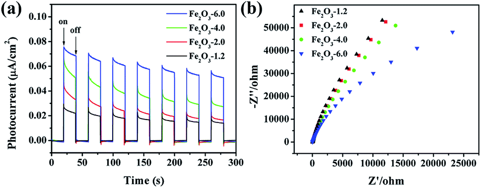
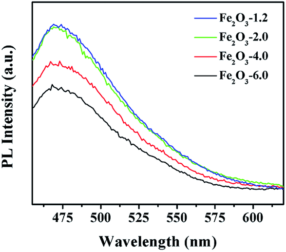
The charge transfer kinetics was studied utilizing photocurrent response and electrochemical impedance spectroscopy (EIS). The photocurrent response curves (Fig. 12a) show an intensity order: Fe2O3-6.0 > Fe2O3-4.0 > Fe2O3-2.0 > Fe2O3-1.2, demonstrating Fe2O3-6.0 with optimal charge separation efficiency. EIS plot (Fig. 12b) discloses Fe2O3-6.0 has the fastest electron transport according to the smallest semicircular, corresponding to the photocurrent result. For further investigating the separation and recombination of electron–hole pairs, the photoluminescence (PL) spectra of the catalysts were recorded at room temperature. As shown in Fig. 13, α-Fe2O3 has a strong peak near 470 nm which attributed to the excitonic PL spectrum.46 The dramatically decreased PL intensity of the α-Fe2O3 samples reflects the higher separation efficiency of photoinduced electron–hole pairs and higher photocatalytic activity,47 which can be ascribed to the shorten transportation path of photogenerated electrons and holes resulting from the reduction of catalyst size.48
 |
| | Fig. 12 (a) Photocurrent response diagrams of the Fe2O3-x under visible irradiation; (b) EIS Nyquist plots of the Fe2O3-x. | |
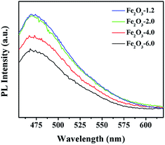 |
| | Fig. 13 PL spectra of the as-prepared Fe2O3 samples. | |
Conclusions
In summary, we prepared high-index faceted α-Fe2O3 with different sizes in a facile way. We demonstrated that the photocatalytic oxygen evolution efficiency of α-Fe2O3 nanocrystals is strongly dependent on the size. Moreover, the optimal size and high-indexed {104} planes endow rhombohedral α-Fe2O3 with excellent water oxidation performance. This study offers a feasible way for the construction of highly efficient water oxidation catalysts through the size tuning of high-index faceted materials.
Conflicts of interest
There are no conflicts of interest to declare.
Acknowledgements
This work was kindly supported by the Natural Science Foundation of China (No. 51564045), the Natural Science Foundation of Xinjiang University (No. BS150232), Open Fund of Guangdong Provincial Key Laboratory of Petrochemical Pollution Process and Control, and Guangdong University of Petrochemical Technology (No. 2018B030322017). The authors acknowledge facilities and staff at the Physical and Chemical testing center of Xinjiang University.
References
- J. Li, R. Guttinger, R. More, F. Song, W. Wan and G. R. Patzke, Chem. Soc. Rev., 2017, 46, 6124–6147 RSC.
- G. Chen, L. Chen, S. M. Ng and T. C. J. C. Lau, ChemSusChem, 2014, 7, 127–134 CrossRef CAS.
- F. A. Frame, T. K. Townsend, R. L. Chamousis, E. M. Sabio, T. Dittrich, N. D. Browning and F. E. Osterloh, J. Am. Chem. Soc., 2011, 133, 7264–7267 CrossRef CAS.
- J. Sato, N. Saito, Y. Yamada, K. Maeda, T. Takata, J. N. Kondo, M. Hara, H. Kobayashi, K. Domen and Y. Inoue, J. Am. Chem. Soc., 2005, 127, 4150–4151 CrossRef CAS.
- Z. Wan, Q. Xu, H. Li, Y. Zhang, Y. Ding and J. Wang, Appl. Catal., B, 2017, 210, 67–76 CrossRef CAS.
- Q. Xu, H. Li, L. Chi, L. Zhang, Z. Wan, Y. Ding and J. Wang, Appl. Catal., B, 2017, 202, 397–403 CrossRef CAS.
- S. M. Barnett, K. I. Goldberg and J. M. Mayer, Nat. Chem., 2012, 4, 498 CrossRef CAS.
- G. C. Dismukes, R. Brimblecombe, G. A. Felton, R. S. Pryadun, J. E. Sheats, L. Spiccia and G. F. Swiegers, Acc. Chem. Res., 2009, 42, 1935–1943 CrossRef CAS.
- R. Brimblecombe, A. Koo, G. C. Dismukes, G. F. Swiegers and L. Spiccia, J. Am. Chem. Soc., 2010, 132, 2892–2894 CrossRef CAS.
- S. Sun, G. Shen, J. Jiang, W. Mi, X. Liu, L. Pan, X. Zhang and J.-J. Zou, Adv. Energy Mater., 2019, 9, 1901505 CrossRef.
- F. Amano, E. Ishinaga and A. Yamakata, J. Phys. Chem. C, 2013, 117, 22584–22590 CrossRef CAS.
- G. R. Bamwenda, T. Uesigi, Y. Abe, K. Sayama and H. Arakawa, Appl. Catal., A, 2001, 205, 117–128 CrossRef CAS.
- J. Huang, Y. Zhang and Y. Ding, ACS Catal., 2017, 7, 1841–1845 CrossRef CAS.
- S. J. Kim, Y. Lee, D. K. Lee, J. W. Lee and J. K. Kang, J. Mater. Chem. A, 2014, 2, 4136–4139 RSC.
- J. Zhu, Z. Yin, D. Yang, T. Sun, H. Yu, H. E. Hoster, H. H. Hng, H. Zhang and Q. Yan, Energy Environ. Sci., 2013, 6, 987–993 RSC.
- Y.-C. Zhang, N. Afzal, L. Pan, X. Zhang and J.-J. Zou, Adv. Sci., 2019, 6, 1900053 CrossRef.
- W. C. Ellis, N. D. McDaniel, S. Bernhard and T. J. Collins, J. Am. Chem. Soc., 2010, 132, 10990–10991 CrossRef CAS PubMed.
- T. K. Townsend, E. M. Sabio, N. D. Browning and F. E. Osterloh, Energy Environ. Sci., 2011, 4, 4270–4275 RSC.
- J. Zhu, Z. Yin, D. Yang, T. Sun, H. Yu, H. E. Hoster, H. H. Hng, H. Zhang and Q. Yan, Energy Environ. Sci., 2013, 6, 987–993 RSC.
- Z. Lin, C. Du, B. Yan and G. Yang, Catal. Sci. Technol., 2019, 9, 5582–5592 RSC.
- Z. Guo, G. Chen, C. Cometto, B. Ma, H. Zhao, T. Groizard, L. Chen, H. Fan, W.-L. Man and S.-M. J. N. C. Yiu, Nat. Catal., 2019, 2, 801–808 CrossRef CAS.
- A. Kusior, K. Michalec, P. Jelen and M. Radecka, Appl. Surf. Sci., 2019, 476, 342–352 CrossRef CAS.
- M. R. Abhilash, A. Gangadhar, J. Krishnegowda, M. Chikkamadaiah and S. Srikantaswamy, RSC Adv., 2019, 9, 25158–25169 RSC.
- G. Shen, L. Pan, Z. Lü, C. Wang, F.-e. Aleem, X. Zhang and J.-J. Zou, Chin. J. Catal., 2018, 39, 920–928 CrossRef CAS.
- X. She, J. Wu, H. Xu, J. Zhong, Y. Wang, Y. Song, K. Nie, Y. Liu, Y. Yang and M. T. F. Rodrigues, Adv. Energy Mater., 2017, 7, 1700025 CrossRef.
- L. Li, X. She, J. Yi, L. Pan, K. Xia, W. Wei, X. Zhu, Z. Chen, H. Xu and H. Li, Appl. Surf. Sci., 2019, 469, 933–940 CrossRef CAS.
- H. Liu, K. Tian, J. Ning, Y. Zhong, Z. Zhang and Y. Hu, ACS Catal., 2019, 9, 1211–1219 CrossRef CAS.
- F. Meng, J. Li, S. K. Cushing, J. Bright, M. Zhi, J. D. Rowley, Z. Hong, A. Manivannan, A. D. Bristow and N. Wu, ACS Catal., 2013, 3, 746–751 CrossRef CAS.
- X.-T. Xu, L. Pan, X. Zhang, L. Wang and J.-J. Zou, Adv. Sci., 2019, 6, 1801505 CrossRef PubMed.
- Z.-S. Pourbakhsh, K. Mohammadi, A. Moshaii, M. Azimzadehirani and A. Hosseinmardi, RSC Adv., 2019, 9, 31860–31866 RSC.
- Q. Xiang, G. Chen and T.-C. Lau, RSC Adv., 2015, 5, 52210–52216 RSC.
- Y. L. Wang, Y. H. Li, X. L. Wang, Y. Hou, A. P. Chen and H. G. Yang, Appl. Catal., B, 2017, 206, 216–220 CrossRef CAS.
- Y. Ma, J. Yang, Y. Yuan, H. Zhao, Q. Shi, F. Zhang, C. Pei, B. Liu and H. Yang, Langmuir, 2017, 33, 8671–8678 CrossRef CAS.
- Y. Zhao, D. Yan, C. Ding, D. Su, Y. Ge, Y. Zhao, H. Zhou, J. Li and H. Jin, J. Power Sources, 2016, 327, 658–665 CrossRef CAS.
- X. Rao, X. Su, C. Yang, J. Wang, X. Zhen and D. Ling, CrystEngComm, 2013, 15, 7250–7256 RSC.
- G. Zhang, Y. Shi, H. Wang, L. Jiang, X. Yu, S. Jing, S. Xing and P. Tsiakaras, J. Power Sources, 2019, 416, 118–124 CrossRef CAS.
- A. Patterson, Phys. Rev., 1939, 56, 978 CrossRef CAS.
- J. S. Hu, L. S. Zhong, W. G. Song and L. J. Wan, Adv. Mater., 2008, 20, 2977–2982 CrossRef CAS.
- W. Yang, F. Gao, G. Wei and L. An, Cryst. Growth Des., 2009, 10, 29–31 CrossRef.
- K. He, B. Song, L. Zhan, W. Lu, J. Li, G. Zhao and G. Han, CrystEngComm, 2016, 18, 754–758 RSC.
- J. Cai, S. Chen, J. Hu, Z. Wang, Y. Ma and L. Qi, CrystEngComm, 2013, 15, 6284–6288 RSC.
- R. D. Rodriguez, D. Demaille, E. Lacaze, J. Jupille, C. Chaneac and J.-P. Jolivet, J. Phys. Chem. C, 2007, 111, 16866–16870 CrossRef CAS.
- M. Lin, H. R. Tan, J. P. Y. Tan and S. Bai, J. Phys. Chem. C, 2013, 117, 11242–11250 CrossRef CAS.
- A. I. Ekimov, A. L. Efros and A. A. Onushchenko, Solid State Commun., 1985, 56, 921–924 CrossRef CAS.
- J. P. Perdew, R. G. Parr, M. Levy and J. L. Balduz Jr, Phys. Rev. Lett., 1982, 49, 1691 CrossRef CAS.
- L. Yu, Y. Zhang, J. He, H. Zhu, X. Zhou, M. Li, Q. Yang and F. Xu, J. Alloys Compd., 2018, 753, 601–606 CrossRef CAS.
- X. An, D. Cheng, L. Dai, B. Wang, H. J. Ocampo, J. Nasrallah, X. Jia, J. Zou, Y. Long and Y. Ni, Appl. Catal., B, 2017, 206, 53–64 CrossRef CAS.
- F. E. Osterloh, Chem. Soc. Rev., 2013, 42, 2294–2320 RSC.
- M. Zhang, J. Luo, X. Liang, B. Yan, M. Baikenov, X. Su, L. Chi and C. Yang, Mater. Lett., 2018, 210, 73–76 CrossRef CAS.
- L. Chi, Q. Xu, X. Liang, J. Wang and X. Su, Small, 2016, 12, 1351–1358 CrossRef CAS.
- D. Hong, Y. Yamada, T. Nagatomi, Y. Takai and S. Fukuzumi, J. Am. Chem. Soc., 2012, 134, 19572–19575 CrossRef CAS.
Footnote |
| † Electronic supplementary information (ESI) available. See DOI: 10.1039/c9ra08561k |
|
| This journal is © The Royal Society of Chemistry 2019 |
Click here to see how this site uses Cookies. View our privacy policy here. 
 Open Access Article
 This Open Access Article is licensed under a Creative Commons Attribution-Non Commercial 3.0 Unported Licence
 c and
Chao Yang
c and
Chao Yang