DOI:
10.1039/C9RA08285A
(Paper)
RSC Adv., 2019,
9, 38496-38504
Dynamic Halbach array magnet integrated microfluidic system for the continuous-flow separation of rare tumor cells†
Received
11th October 2019
, Accepted 8th November 2019
First published on 25th November 2019
Abstract
Circulating tumor cells (CTCs), the most representative rare cells in peripheral blood, have received great attention due to their clinical utility in liquid biopsy. The downstream analysis of intact CTCs isolated from peripheral blood provides important clinical information for personalized medicine. However, current CTC isolation and detection methods have been challenged by their extreme rarity and heterogeneity. In this study, we developed a novel microfluidic system with a continuously moving Halbach array magnet (dHAMI microfluidic system) for negative isolation CTCs from whole blood, which aimed to capture non-target white blood cells (WBCs) and elute target CTCs. The dynamic and continuous movement of the Halbach array magnet generated a continuous magnetic force acting on the magnetic bead-labelled WBCs in the continuous-flow fluid to negatively exclude the WBCs from the CTCs. Furthermore, the continuously moving magnetic field effectively eliminated the effect of magnetic bead aggregation on the fluid flow to realize the continuous-flow separation of the CTCs without a sample loading volume limitation. The experimental procedure for CTC negative isolation using the dHAMI microfluidic system could be completed within 40 min. Under the optimized experimental conditions of the dHAMI microfluidic system, including the flow rate and concentration of the immunomagnetic bead, the average CTC capture rate over a range of spiked cell numbers (50–1000 cancer cells per mL) was up to 91.6% at a flow rate of 100 μL min−1. Finally, the CTCs were successfully detected in 10 of 10 (100%) blood samples from patients with cancer. Therefore, the dHAMI microfluidic system could effectively isolate intact and heterogeneous CTCs for downstream cellular and molecular analyses, and this robust microfluidic platform with an excellent magnetic manipulation performance also has great application potential for the separation of other rare cells.
Introduction
Rare cells are defined as cells with less than 1000 per mL of biofluid, which is important for the diagnosis and prognosis of human diseases.1,2 Circulating tumor cells (CTCs) are one of the most typical rare cells that are derived from the primary tumors of patients with cancer and disseminate through blood circulation to form metastatic tumors at distant organs.3–5 The liquid biopsy analyses of CTCs in the blood of cancer patients have received great attention in the past decade because the prognostic values of CTC counts for personalized medicine have already been demonstrated in large scale clinical studies.6,7 Downstream studies of the intact CTCs isolated from blood can also provide more valuable information for antitumor therapy at the protein, RNA, and DNA levels.8,9 The cellular heterogeneity and rarity of CTCs are two major challenges for CTC isolation and detection technologies that significantly limit the clinical utility of CTCs in liquid biopsy.
Most existing technologies focus on the positive isolation of CTCs, which aim to capture CTCs based on surface biomarkers such as an epithelial cell adhesion molecule (EpCAM) and cytokeratin (CK) or physical properties of cancer cells such as size and deformability.10 The other method is negative isolation, which aims to capture non-target cells such as white blood cells (WBCs) and release cancer cells.11 For the positive isolation method, the high sensitivity of EpCAM-positive cell detection and the high purity of isolated cells are its main advantages.12 The most obvious limitation of the positive isolation method is that the subpopulations of cancer cells without or with a very low epithelial marker expression cannot be captured by this method.13 The use of antibodies to positively capture CTCs in blood also do not obtain the intact cancer cells, which is unsuitable for downstream studies of CTCs.14 The principle of the negative isolation method is not based on the characteristics of cancer cells. Therefore, it does not lose some subpopulations of cancer cells and obtains all cancer cells in the blood. Compared with positive isolation methods, the CTCs isolated by negative isolation are intact cancer cells and suitable for downstream analyses such as molecular identification and functional studies.15 However, the limitation of the negative isolation method is an unsatisfactory purity of isolated CTCs, which will interfere with the subsequent analysis.
Current commercial products for CTC isolation are mainly based on immunomagnetic and microfluidic separation methods.16 Magnetic activated cell sorting is one of the most conventional approaches for CTC isolation that utilizes an external magnetic field to separate the target cells labelled with immunomagnetic beads. One example of commercialized immunomagnetic products for CTC detection is the U.S. Food and Drug Administration (FDA) approved CellSearch system, which positively isolates CTCs using EpCAM antibodies.17,18 Another commercialized immunomagnetic product for CTC detection is called EasySep™, which negatively selects blood cells.19 However, current commercial immunomagnetic products for CTCs require several sample processing and transfer steps, which may result in the loss of CTCs during the operation process.20 To improve these limitations, microfluidic devices based on magnetic continuous-flow separation for CTC detection have been developed.21 Recent studies have also demonstrated that the microfluidic magnetic separation platforms enabled the efficient and continuous-flow separation of CTCs.22 There are some challenges for microfluidic magnetic separation platforms due to the magnetic beads aggregated in a microchannel using a fixed magnet.23 The aggregation of magnetic beads is not fully exposed to the reagent and affects the flow of the microchannel fluid, which results in the reduction of the efficiency of cell separation. Therefore, the magnetic field is an important factor that determines the efficiency of the magnetic cell separation. The design and optimization of a microfluidic system and its external magnetic field will improve the efficiency and throughput of CTC isolation methods.
In this study, we presented a continuous-flow separation method in a microfluidic system with a dynamic Halbach array magnet (dHAMI microfluidic system) to realize a high efficiency CTC negative isolation (Fig. 1A). The dHAMI microfluidic system used the ring-shaped microfluidic channel with a continuously moving magnetic field to eliminate the magnetic beads aggregated in the microchannel and negatively isolate CTCs from blood samples. The rare cell isolation condition and throughput of the dHAMI microfluidic system were evaluated and optimized using polystyrene particles or blood samples spiked with cancer cells. Finally, clinical blood samples of patients with cancer were used to verify the performance of this microfluidic system. In conclusion, we established a robust negative isolation method for CTC capture using a novel microfluidic system based on magnetic continuous-flow separation, and it has shown great promise for providing intact cancer cells for downstream analysis.
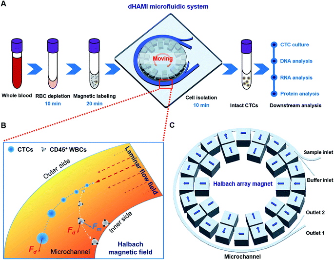 |
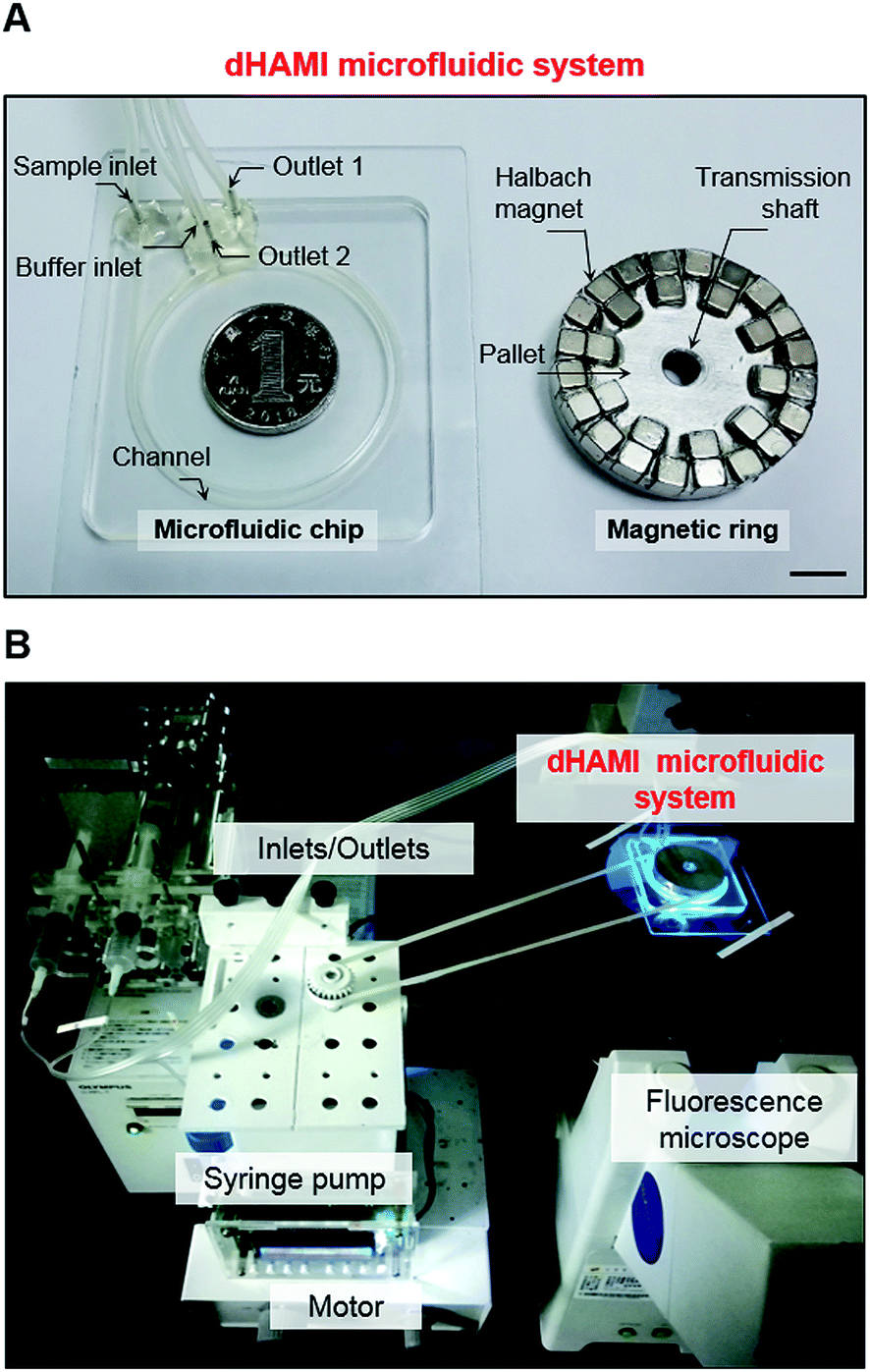
| | Fig. 1 Illustration of the dynamic Halbach array magnet integrated (dHAMI) microfluidic system. (A) Schematic diagram of the experimental procedure for CTC negative isolation using a microfluidic system with dynamic Halbach array magnet (dHAMI microfluidic system). The operation time of dHAMI microfluidic system for CTC isolation is 40 min. (B) Cell separation principle and force analysis in the microchannel of dHAMI microfluidic system. (C) Schematic illustration of microfluidic chip with sample inlet, buffer inlet, outlet 1 and outlet 2. The width of microchannel is 1 mm, and the height of microchannel is 0.5 mm. The blue arrow indicates the direction of magnetization of each permanent magnet cube. | |
Materials and methods
Theory
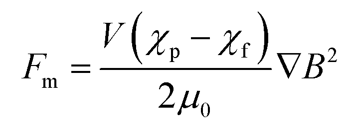
In our microfluidic chip, the drag force and the magnetic force were dominant forces for the magnetic bead-labelled cells (Fig. 1B). According to Stokes' law, the drag force, Fd, acting on the magnetic bead-labelled cells or unlabelled cells in the microfluidic chip was described by the following eqn (1):21,24where η and νf are the viscosity and velocity of the fluids, respectively. R and νc are the radius and velocity of the magnetic bead-labelled cells or unlabelled cells in the microfluidic chip, respectively. The magnetic force acting on the magnetic bead-labelled cells could be estimated as:21,24| |
 | (2) |
where V is the volume of the magnetic bead-labelled cells, χp and χf are the magnetic susceptibilities of the magnetic bead-labelled cells and the fluid, respectively, the physical constant μ0 is the permeability of vacuum, and B is the magnetic flux density.
Dynamic Halbach array magnet integrated (dHAMI) microfluidic system design
The dHAMI microfluidic system consisted of a ring-shaped microfluidic chip and a ring-shaped Halbach array magnet. The magnet and the microfluidic chip were located in the same concentric circle, and the magnet was placed on the medial wall of the microfluidic chip (Fig. 1C and 2A). The microfluidic chip was composed of a ring-shaped channel with two inlets and two outlets. As shown in Fig. 1C, one inlet was named the sample inlet and the other inlet was named the buffer inlet. One outlet was named outlet 1 and the other outlet was named outlet 2. Two syringes attached to the syringe pump were connected to the two inlets of the chip through polytetrafluoroethylene (PTFE) pipes. The ring-shaped Halbach array magnet was separated into three parts that included a magnetic ring, a pallet of the magnetic ring, and a transmission shaft (Fig. 2A). The stepper motor made the magnet move forward in a circular motion by controlling the transmission shaft.
 |
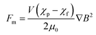
| | Fig. 2 (A) Photograph of the fabricated dHAMI microfluidic system. Scale bar is 10 mm. (B) Photograph of the workstation of dHAMI microfluidic system for CTCs isolation. | |
dHAMI microfluidic system fabrication and assembly
The polymethylmethacrylate (PMMA) microfluidic chip was fabricated according to a standard procedure described in previous literature.25,26 Briefly, the flow channels and inlets/outlets of the microfluidic chip were designed using a 3D computer aided design software Pro/Engineer Wildfire 5.0. The channel of the microfluidic chip was 1 mm wide and the height of the channel was 0.5 mm (Fig. 1C and 2A). The channel was fabricated by cutting the designed microchannel on a transparent PMMA sheet using a CO2 laser cutting machine. The channel was sealed with functionalized pressure sensitive single-sided tapes. Finally, the inlets and outlets of the microfluidic chip were fabricated by cutting through the sheet and the inlets/outlets were connected with PTFE pipes (Fig. 2A).
The magnetic ring of the Halbach array magnet comprised thirty permanent magnet cubes with a uniform polarity for each size, 5 mm (L) × 5 mm (W) × 5 mm (H), and the diameter of the magnetic ring was 45 mm. The cubes were of a neodymium–iron–boron (NdFeB) material and wrapped by aluminium frames. The magnetization of the magnets in the magnetic ring was arranged in a Halbach array fashion. The magnetization direction of each cube is shown in Fig. 1C. The aluminium pallet was fabricated by a computer-controlled milling cutter, and the cubes were arranged in a Halbach array fashion and fixed on the disc-shaped pallet (Fig. 2A). The assembled magnet that was embedded in the microfluidic chip was connected to the stepper motor via a transmission shaft to generate a moving magnetic field (Fig. 2B).
Cell culture and staining
Human gastric cancer AGS cells were used in this study to mimic rare CTCs. The cancer cells were cultured in RPMI-1640 medium (Hyclone, USA) supplemented with 10% fetal bovine serum (ExCell Bio, Shanghai, China) and incubated at 37 °C under a humidified 5% CO2 atmosphere. When the cell confluence reached 90%, the cells were digested with 0.25% trypsin and resuspended with PBS to generate a single-cell suspension. The human AGS cancer cells were labelled with CellTracker Green CMFDA dye (Invitrogen, Thermo Fisher Scientific, USA) according to the manufacturer's protocol.
Polystyrene particle sample preparation
To reduce particle adhesion to the channel wall, the microfluidic channel and two syringes were filled with 1% (w/w) Pluronic F-127.27 According to previous literature, the cellular size of the CTCs ranged from 4 μm to 30 μm.28,29 To evaluate the performance of the microfluidic system, the fluorescent polystyrene particles with a size of 15 μm (green) were used to mimic the CTCs. Magnetic beads (1 × 10⁶ particles per mL) were mixed with fluorescent particles (1000 particles per mL) and suspended in 1 mL of PBSP (0.01% Pluronic F-127, v/v, Sangon Biotech, Shanghai, China) to prevent agglomeration.27
Human whole blood sample preparation
This study was performed in strict accordance with the guidelines of “Ethics of Biomedical Research with Human Involved (National Health Commission of People's Republic of China)”, and this study was approved by the Ethics Committee of Xijing Hospital of Air Force Medical University (Xi'an, China). Human whole blood samples were obtained from healthy volunteers and 10 patients with gastric cancer. Informed consents were obtained from all of the human participants in this study. We spiked human AGS cells prestained with CellTracker Green into 3 mL of fresh human whole blood. The spiked blood samples were treated with red blood cell lysis buffer for 10 min (RBCL, Tiangen, Beijing, China) according to the manufacturer's protocol. The treated blood samples were incubated with CD45-labelled immunomagnetic beads (biolegend, CA, USA) for 20 min according to the manufacturer's protocol. After incubation, the samples were diluted to 1 mL with PBSP. This mixture was then injected into the microfluidic chip using a syringe pump.
Sorting experiment
During the sorting experiment, the mixed particles or treated blood sample was diluted to 1 mL with PBSP and injected into the sample inlet through a syringe pump while the PBSP buffer was injected into the buffer inlet through another syringe pump (Fig. 2B). The flow rate of the blood sample was set at 25–200 μL min−1. Meanwhile, the stepper motor was turned on and drove the magnet to move forward in a circular motion at a speed of 120 rpm. After the cell sorting process, the separated cancer cells flowed out from outlet 1 and were collected for further identification. When the magnet was removed, the WBCs with CD45-labelled immunomagnetic beads flowed out from outlet 2.
Cell identification
The putative cancer cells collected from the clinical blood samples using the dHAMI microfluidic system were identified by immunofluorescent staining. The collected cells were fixed on a glass slide using 4% paraformaldehyde, followed by incubation with CK Pan Alexa fluor 488 conjugated antibodies (Invitrogen), EpCAM FITC conjugated antibodies (Invitrogen), CD45 PE conjugated antibodies (Invitrogen), and cellular nuclei that were counterstained with Hoechst. Captured cell counting and imaging were performed using a fluorescence microscope. Hoechst dye positive, CK dye positive, and CD45 dye negative cells or Hoechst dye positive, EpCAM dye positive, and CD45 dye negative cells were considered as the CTCs.
Cell capture rate
The CTC capture rate of the microfluidic system was calculated using eqn (3), and the WBC depletion rate of the microfluidic system was calculated using eqn (4).| |
 | (3) |
| |
 | (4) |
Cf is the number of cancer cells counted under a fluorescence microscope (green) and Cs is the total number of cancer cells spiked into the blood samples. Nt is the total number of WBCs in the blood sample. Nm is the number of WBCs after CD45 immunomagnetic WBC depletion. Both Nt and Nm were determined by an automated cell counter.
Statistical analysis
GraphPad Prism 7.0 statistical software was used for statistical analyses. All data were represented as mean ± standard deviation (SD) from three independent experiments.
Results and discussion
Design and separation principle of dHAMI microfluidic system
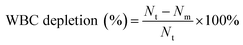
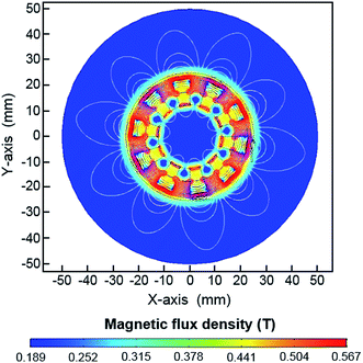
A dynamic magnetic field is created by a moving or rotating permanent magnet that can induce positive and negative magnetophoresis.30 Applications using a dynamic magnetic field in microfluidics for the mixing and trapping of particles or cells have been reported.30,31 Unlike these traditional magnetic microfluidic systems, the dHAMI microfluidic system uses a dynamically moving Halbach array magnet as the external magnetic field to separate rare tumor cells through positive magnetophoresis. The permanent magnet arranged in a Halbach fashion increases the magnetic field on one side of the array while eliminating it on the other side, which produces a high magnetic flux density gradient.32 A large magnetic field gradient created by the permanent magnet was required to enhance the separation efficiency of the magnetic cell separation.33 Thus, the magnetic field of the Halbach array magnet had an excellent magnetic manipulation, which was more suitable for the sorting of magnetic materials.34 The magnetic field simulation of the Halbach array magnet was used by COMSOL Multiphysics 5.4 software. Fig. 3 shows a simulated magnetic flux density made by a Halbach array magnetic ring. We designed a ring-shaped microchannel that was located on the lateral wall of the Halbach array magnetic ring. The magnetic flux densities at the medial and the lateral wall of the microchannel were also shown in Fig. S1.† Thus, these results indicated that the large magnetic field gradient created by the Halbach array magnet could effectively capture the magnetic labelled target cells. Furthermore, the fixed magnet as the external magnetic field usually caused the magnetic beads to aggregate and nonuniformly distribute on the microchannel wall, which may have affected the flow of the fluid in the microchannel and reduced the magnetic manipulation of the magnetic field.23 As shown in Fig. 4, the fixed Halbach array magnet also led to the aggregation of magnetic beads and nonuniform distribution on the microchannel wall. To prevent the aggregation of the magnetic beads in the microchannel, a dynamic and continuously moving Halbach array magnet was developed. The continuous movement of the Halbach array magnet in the direction opposite to the continuous fluid flow allowed the magnetic beads to be sufficiently exposed to the buffers and uniformly distributed in the microchannel (Movie S1†). In addition, the ring-shaped microchannel in the horizontal direction was designed to accommodate the magnetic ring of the Halbach array magnet, which could realize the continuous-flow cell separation with a high throughput under the continuous action of magnetic force.
 |
| | Fig. 3 Numerical simulation of the magnetic flux density of the Halbach array magnet. Magnetic field distribution of the Halbach array magnet. The contour plot is for the magnetic potentials. | |
 |
| | Fig. 4 Distribution of magnetic beads under Halbach array magnetic field and moving Halbach array magnetic field. Scale bar is 200 μm. | |
To evaluate the dHAMI microfluidic system separation performance, the 15 μm fluorescent particles (green) with a concentration of 1000 particles per mL mimicked the rarity of CTCs. These particles were mixed with the magnetic beads for injection into the microfluidic chip. The trajectories of the two different particles in the microchannel of the dHAMI microfluidic system were investigated using a fluorescence microscope. When the continuously moving magnetic field was applied, the magnetic beads moved toward the medial wall of the microchannel under the continuous action of the magnetic force (Movie S1†). The fluorescent particles maintained their positions near the centre of the microchannel and continuously flowed under the continuous action of the drag force (Movie S2†). Finally, the fluorescent particles passed through the microchannel and were collected at outlet 1. Therefore, this result suggested that the dHAMI microfluidic system enabled the continuous-flow separation of rare cells.
Optimization of dHAMI microfluidic system performance
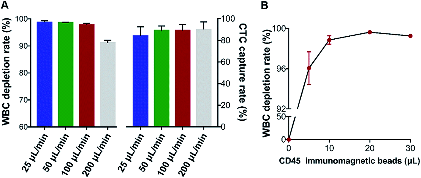
To determine the experimental conditions of the dHAMI microfluidic system, the flow rate for sample injection was optimized. We spiked fluorescent-labelled AGS cancer cells into 3 mL of the whole blood samples (500 cancer cells per mL) and isolated these spiked blood samples using 10 μL of the CD45-labelled immunomagnetic beads (according to the manufacturer's protocol) under various flow rates from 25 μL min−1 to 200 μL min−1. The CTC capture rate and the WBC depletion rate at different flow rates are shown in Fig. 5A. As the flow rate was increased from 100 to 200 μL min−1, the WBC depletion rate was reduced from 97.7% to 91.2%. Compared with a flow rate of 50 μL min−1, the CTC capture rate or WBC depletion rate had no significant change at the 100 μL min−1 flow rate. The high throughput (i.e., flow rate) microfluidic chip demonstrated that the large samples were detected in a short time, which improved the accuracy of rare CTC detection.35 A high flow rate was found that led to a high shear force, which detached the cell from the microchannel of the microfluidic chip.36 Thus, the optimal flow rate of the dHAMI microfluidic system was determined by a balance of the throughput, CTC capture rate, and WBC depletion rate. We determined that the optimal flow rate of the dHAMI microfluidic system was 100 μL min−1.
 |
| | Fig. 5 Optimization of the separation conditions. (A) CTC capture rate and WBC depletion rate of the dHAMI microfluidic system at different flow rates. (B) WBC depletion rate of the dHAMI microfluidic system under different volumes of CD45-labelled immunomagnetic beads. | |
Negative enrichment for CTC isolation usually aims to capture or eliminate the WBCs in blood using CD45-labelled immunomagnetic beads. Thus, it is important to find the optimal concentration of CD45-labelled immunomagnetic beads that can sufficiently bind with the WBCs.37 A WBC sample of 3 × 10⁶ cells was incubated with CD45-labelled immunomagnetic beads at four different ratios ranging from 5![[thin space (1/6-em)]](https://www.rsc.org/images/entities/char_2009.gif) :1 (5 μL beads: 3 × 10⁶ WBCs) to 30:1, and the WBC depletion rate was evaluated following dHAMI microfluidic system separation under the optimal flow rate (100 μL min−1). As shown in Fig. 5B, the average WBCs capture rate reached the saturation point at a ratio of 20:1 (99.6 ± 0.2%). Thus, we determined the optimal concentration of CD45-labelled immunomagnetic beads to be a ratio of 20:1.
:1 (5 μL beads: 3 × 10⁶ WBCs) to 30:1, and the WBC depletion rate was evaluated following dHAMI microfluidic system separation under the optimal flow rate (100 μL min−1). As shown in Fig. 5B, the average WBCs capture rate reached the saturation point at a ratio of 20:1 (99.6 ± 0.2%). Thus, we determined the optimal concentration of CD45-labelled immunomagnetic beads to be a ratio of 20:1.
Isolation of CTCs from blood samples spiked with cancer cells
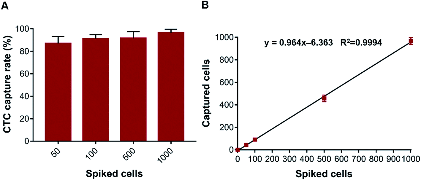
According to the optimal experimental conditions (flow rate, 100 μL min−1; concentration of CD45-labelled immunomagnetic beads, a ratio of 20:1), we further evaluated the CTC capture rate and the WBC depletion rate for the dHAMI microfluidic system using a human whole blood sample spiked with cancer cells. The prepared 3 mL whole blood samples were spiked with AGS cells (50, 100, 500, and 1000 cancer cells per mL) and separated under the optimal flow rate (100 μL min−1). The average capture rate increased from 87.0% to 96.6% as the spiked cancer cell concentration increased from 50 to 1000 cancer cells per mL (Fig. 6A). The number of cancer cells isolated using the dHAMI microfluidic system was proportional to the number of cancer cells spiked into the blood samples (range: 50–1000 cancer cells per mL, Fig. 6B). The average capture rate of the CTCs across the spiked range of 50 to 1000 cancer cells per mL was 91.6 ± 3.9%. The best experimental results for the recent negative isolation methods based on immunomagnetic separation for CTC isolation is summarized in Table 1.38–42 The CTC capture efficiency of our method showed a higher capture rate than most methods. Furthermore, the dHAMI microfluidic system had an equally excellent WBC depletion rate compared to the other negative isolation methods. In addition, the main limitation of microfluidic technologies is the low throughput of the microchannel that leads to a long separation time when processing a large volume blood sample.9,43 In this study, the dHAMI microfluidic system only required 10 min to process the 1 mL sample input (3 mL whole blood) (Fig. 1A). In summary, these results indicated that the dHAMI microfluidic system was capable of isolating rare CTCs from spiked blood samples with a high capture efficiency.
 |
| | Fig. 6 Isolation CTCs from whole blood samples spiked with cancer cells. (A) CTC capture rate of the dHAMI microfluidic system from whole blood samples spiked with rare number AGS cells (50–1000 AGS cells per ml). (B) Relationship between the number of captured cancer cells and the number of spiked cancer cells (y = 0.964x − 6.363, r2 = 0.9994). | |
Table 1 Negative isolation methods based on immunomagnetic separation for CTC isolation
| Technology |
Capture efficiency |
WBC depletion |
Throughput |
| Microfluidic disk38 |
70.0% |
99.9% |
NA |
| Microfluidic platform39 |
90.0% |
90.0% |
2 mL h−1 |
| Microfluidic platform16,40 |
75.0% |
85.0% |
0.4 mL h−1 |
| Integrated microfluidic chip41 |
94.2% |
99.6% |
>12 mL h−1 |
| EasySep™9,41 |
81.3% |
99.9% |
1–4 mL h−1 |
| Two-step negative isolation42 |
84.0% |
98.8% |
NA |
| dHAMI |
96.6% |
99.6% |
6 mL h−1 |
Isolation and identification of CTCs from clinical samples
To determine the clinical utility of the dHAMI microfluidic system for CTC detection in clinical blood samples, 3 mL of whole blood samples from 10 patients with gastric cancer were isolated using the dHAMI microfluidic system. Immunofluorescence staining was performed for the identification and enumeration of CTCs. The isolated cells showing Hoechst+/CK+/CD45− (Hoechst blue and CK green) or Hoechst+/EpCAM+/CD45− (Hoechst blue and EpCAM green) were identified as CTCs, and those cells showing Hoechst+/CK−/CD45+ (Hoechst blue and CD45 red) or Hoechst+/EpCAM−/CD45+ (Hoechst blue and CD45 red) were regarded as WBCs. Moreover, the size of the CTCs was larger than that of the WBCs under the fluorescence microscope (Fig. 7). The enumeration results and representative images of the CTCs are summarized in Table 2 and Fig. 7. Using the dHAMI microfluidic system, the CTCs were detected in 10 of 10 patients with gastric cancer and ranged from 2 to 8 CTCs. Therefore, these results indicated that the dHAMI microfluidic system could be successfully applied for CTC isolation and detection in real clinical blood samples.
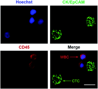 |
| | Fig. 7 Fluorescent images of isolated cells using the dHAMI microfluidic system from a clinical blood sample of the patient with gastric cancer. Cells stained with Hoechst positive, CD45 negative, CK positive or Hoechst positive, CD45 negative, EpCAM positive are regarded as CTCs (green arrow). Red arrow shows the WBC (Hoechst positive, CD45 positive, CK negative or EpCAM negative). Scale bar is 10 μm. | |
Table 2 Number of CTCs counted in human whole blood samples
| Cohort |
Sample ID |
Blood volume (mL) |
Diagnosis |
CTCs |
| Cancer patients |
1 |
3 |
Gastric cancer |
7 |
| 2 |
3 |
Gastric cancer |
6 |
| 3 |
3 |
Gastric cancer |
6 |
| 4 |
3 |
Gastric cancer |
5 |
| 5 |
3 |
Gastric cancer |
8 |
| 6 |
3 |
Gastric cancer |
7 |
| 7 |
3 |
Gastric cancer |
5 |
| 8 |
3 |
Gastric cancer |
4 |
| 9 |
3 |
Gastric cancer |
2 |
| 10 |
3 |
Gastric cancer |
6 |
Conclusions
In summary, we developed and fabricated a microfluidic system with a dynamic Halbach array magnet to efficiently capture CTC from whole blood with a high throughput (6 mL h−1). The optimized system exhibited an average CTC capture rate that was more than 90.0%. The intact and heterogeneous CTC isolated by this platform allow for subsequent cellular and molecular analyses such as CTC culture and next generation sequencing that will expand the clinical utility of CTCs as a real-time target for liquid biopsy. We believe that this novel, simple, fast, and robust dHAMI microfluidic system enables a highly efficient and continuous-flow isolation of rare tumor cells from whole human blood. It could also be potentially utilized for other rare cell sorting studies such as circulating endothelial cells, circulating fetal cells and stem cells. Furthermore, this system is also appropriate for integration with other analytical devices to achieve the rapid and automated identification and analysis of rare cells. Future work will focus on the further miniaturization of this system and optimization of the channel sizes to suit the requirements of different rare cells.
Abbreviations
| CK | Cytokeratin |
| CMFDA | 5-Chloromethylfluorescein diacetate |
| CTC | Circulating tumor cell |
| EpCAM | Epithelial cell adhesion molecule |
| FDA | U.S. food and drug administration |
| FITC | Fluorescein isothiocyanate |
| NA | Not available |
| PBS | Phosphate buffer saline |
| PE | Phycoerythrin |
| PMMA | Polymethylmethacrylate |
| PTFE | Polytetrafluoroethylene |
| RBCL | Red blood cell lysis buffer |
| WBC | White blood cell |
Conflicts of interest
There are no conflicts to declare.
Acknowledgements
This work was supported by the National Natural Science Foundation of China (No. 81301513 and No. 31570168), the Natural Science Foundation of Shaanxi Province of China (No. 2018JM7032), and the National Key R&D Program of China (No. 2017YFC1308600).
References
- M. Antfolk and T. Laurell, Anal. Chim. Acta, 2017, 965, 9–35 CrossRef CAS PubMed.
- Y. Chen, P. Li, P. H. Huang, Y. Xie, J. D. Mai, L. Wang, N. T. Nguyen and T. J. Huang, Lab Chip, 2014, 14, 626–645 RSC.
- V. Ortiz and M. Yu, Trends Cell Biol., 2018, 28, 764–775 CrossRef PubMed.
- J. Massague and A. C. Obenauf, Nature, 2016, 529, 298–306 CrossRef CAS PubMed.
- A. Bardelli and K. Pantel, Cancer Cell, 2017, 31, 172–179 CrossRef CAS PubMed.
- E. Heitzer, I. S. Haque, C. Roberts and M. R. Speicher, Nat. Rev. Genet., 2019, 20, 71–88 CrossRef CAS PubMed.
- C. Alix-Panabieres and K. Pantel, Cancer Discovery, 2016, 6, 479–491 CrossRef CAS PubMed.
- C. Dive and G. Brady, Cell, 2017, 168, 742 CrossRef CAS PubMed.
- P. Banko, S. Y. Lee, V. Nagygyorgy, M. Zrinyi, C. H. Chae, D. H. Cho and A. Telekes, J. Hematol. Oncol., 2019, 12, 48 CrossRef PubMed.
- Z. Shen, A. Wu and X. Chen, Chem. Soc. Rev., 2017, 46, 2038–2056 RSC.
- P. Patil, M. Madhuprasad, T. Kumeria, D. Losic and M. Kurkuri, RSC Adv., 2015, 5, 89745–89762 RSC.
- M. Cristofanilli, G. T. Budd, M. J. Ellis, A. Stopeck, J. Matera, M. C. Miller, J. M. Reuben, G. V. Doyle, W. J. Allard, L. W. Terstappen and D. F. Hayes, N. Engl. J. Med., 2004, 351, 781–791 CrossRef CAS PubMed.
- M. Yu, A. Bardia, B. S. Wittner, S. L. Stott, M. E. Smas, D. T. Ting, S. J. Isakoff, J. C. Ciciliano, M. N. Wells, A. M. Shah, K. F. Concannon, M. C. Donaldson, L. V. Sequist, E. Brachtel, D. Sgroi, J. Baselga, S. Ramaswamy, M. Toner, D. A. Haber and S. Maheswaran, Science, 2013, 339, 580–584 CrossRef CAS PubMed.
- J. A. Thiele, K. Bethel, M. Kralickova and P. Kuhn, Annu. Rev. Phytopathol., 2017, 12, 419–447 CrossRef CAS PubMed.
- W. Yue, Z. Tan, X. Li, F. Liu and C. Wang, Trends Anal. Chem., 2019, 117, 101–115 CrossRef CAS.
- H. Cho, J. Kim, H. Song, K. Y. Sohn, M. Jeon and K. H. Han, Analyst, 2018, 143, 2936–2970 RSC.
- D. F. Hayes, M. Cristofanilli, G. T. Budd, M. J. Ellis, A. Stopeck, M. C. Miller, J. Matera, W. J. Allard, G. V. Doyle and L. W. Terstappen, Clin. Cancer Res., 2006, 12, 4218–4224 CrossRef CAS PubMed.
- S. Riethdorf, H. Fritsche, V. Muller, T. Rau, C. Schindlbeck, B. Rack, W. Janni, C. Coith, K. Beck, F. Janicke, S. Jackson, T. Gornet, M. Cristofanilli and K. Pantel, Clin. Cancer Res., 2007, 13, 920–928 CrossRef CAS PubMed.
- Z. Liu, A. Fusi, E. Klopocki, A. Schmittel, I. Tinhofer, A. Nonnenmacher and U. Keilholz, J. Transl. Med., 2011, 9, 70 CrossRef PubMed.
- B. D. Plouffe, M. Mahalanabis, L. H. Lewis, C. M. Klapperich and S. K. Murthy, Anal. Chem., 2012, 84, 1336–1344 CrossRef CAS PubMed.
- M. Hejazian, W. Li and N. T. Nguyen, Lab Chip, 2015, 15, 959–970 RSC.
- F. S. Iliescu, D. P. Poenar, F. Yu, M. Ni, K. H. Chan, I. Cima, H. K. Taylor, I. Cima and C. Iliescu, Biomicrofluidics, 2019, 13, 41503 CrossRef PubMed.
- J. Verbarg, K. Kamgar-Parsi, A. R. Shields, P. B. Howell Jr and F. S. Ligler, Lab Chip, 2012, 12, 1793–1799 RSC.
- K. Hoshino, Y. Y. Huang, N. Lane, M. Huebschman, J. W. Uhr, E. P. Frenkel and X. Zhang, Lab Chip, 2011, 11, 3449–3457 RSC.
- Y. Ren, S. Ray and Y. Liu, Sci. Rep., 2019, 9, 4824 CrossRef PubMed.
- H. Klank, J. P. Kutter and O. Geschke, Lab Chip, 2002, 2, 242–246 RSC.
- P. Deng, C. Fu and Z. Wu, RSC Adv., 2018, 8, 35512–35520 RSC.
- A. Abdulla, W. Liu, A. Gholamipour-Shirazi, J. Sun and X. Ding, Anal. Chem., 2018, 90, 4397–4405 CrossRef CAS PubMed.
- N. Sun, X. Li, Z. Wang, Y. Li and R. Pei, Biosens. Bioelectron., 2018, 102, 157–163 CAS.
- A. Munaz, M. J. A. Shiddiky and N. Nam-Trung, Biomicrofluidics, 2018, 12, 031501 Search PubMed.
- A. Munaz, H. Kamble, M. J. A. Shiddiky and N. Nam-Trung, RSC Adv., 2017, 7, 52465–52474 CAS.
- K. Halbach, Nucl. Instrum. Methods, 1980, 169, 1–10 CAS.
- C. M. Earhart, C. E. Hughes, R. S. Gaster, C. C. Ooi, R. J. Wilson, L. Y. Zhou, E. W. Humke, L. Xu, D. J. Wong, S. B. Willingham, E. J. Schwartz, I. L. Weissman, S. S. Jeffrey, J. W. Neal, R. Rohatgi, H. A. Wakelee and S. X. Wang, Lab Chip, 2014, 14, 78–88 RSC.
- J. Wu, Y. Cui, S. Xuan and X. Gong, Microfluid. Nanofluid., 2018, 22, 103 CrossRef.
- R. Negishi, K. Takai, T. Tanaka, T. Matsunaga and T. Yoshino, Anal. Chem., 2018, 90, 9734–9741 CrossRef CAS PubMed.
- K. A. Hyun, T. Y. Lee and H. I. Jung, Anal. Chem., 2013, 85, 4439–4445 CrossRef CAS PubMed.
- J. Jiang, H. Zhao, W. Shu, J. Tian, Y. Huang, Y. Song, R. Wang, E. Li, D. Slamon, D. Hou, X. Du, L. Zhang, Y. Chen and Q. Wang, Sci. Rep., 2017, 7, 42612 CAS.
- C. L. Chen, K. C. Chen, Y. C. Pan, T. P. Lee, L. C. Hsiung, C. M. Lin, C. Y. Chen, C. H. Lin, B. L. Chiang and A. M. Wo, Lab Chip, 2011, 11, 474–483 RSC.
- B. N. Sajay, C. P. Chang, H. Ahmad, P. Khuntontong, C. C. Wong, Z. Wang, P. D. Puiu, R. Soo and A. R. Rahman, Biomed. Microdevices, 2014, 16, 537–548 CAS.
- W. Luo, S. Tsai, K. Hsieh and G. Lee, J. Micromech. Microeng., 2015, 25, 084007 CrossRef.
- T. Y. Lee, K. Hyun, S. Kim and H. Jung, Sens. Actuators, B, 2017, 238, 1144–1150 CrossRef CAS.
- C. Liao, C. Hsieh, H. Wang, W. Chou, T. Chiu, J. Chang, A. C. Chao and M. Wu, RSC Adv., 2017, 7, 29339–29349 RSC.
- K. Wang, L. Zhou, S. Zhao, Z. Cheng, S. Qiu, Y. Lu, Z. Wu, W. A. Abdel, H. Mao and J. Zhao, Talanta, 2019, 200, 169–176 CrossRef CAS PubMed.
Footnotes |
| † Electronic supplementary information (ESI) available. See DOI: 10.1039/c9ra08285a |
| ‡ These authors have contributed equally to this work. |
|
| This journal is © The Royal Society of Chemistry 2019 |
Click here to see how this site uses Cookies. View our privacy policy here. 
 Open Access Article
 This Open Access Article is licensed under a Creative Commons Attribution-Non Commercial 3.0 Unported Licence
 *b
*b