 Open Access Article
Nitrogen-doped hierarchical porous CNF derived from fibrous structured hollow ZIF-8 for a high-performance supercapacitor electrode†
Hongjiao Nie *,
Kan Mi,
Lanlan Song and
Xiuwen Zheng
 *
*
Key Laboratory of Functional Nanomaterials and Technology in Universities of Shandong, School of Chemistry and Chemical Engineering, Linyi University, Linyi 276000, China. E-mail: niehongjiao2011@163.com; zhengxiuwen@lyu.edu.cn
First published on 9th December 2019
Abstract
Hollow ZIF-8 was assembled into fiber to fabricate a nitrogen-doped hierarchical porous CNF electrode, which exhibits specific capacitance of 394 F g−1 at 1 A g−1 and excellent rate performance with a retention of up to 76.1% at 20 A −1, exceeding those of many previously reported 1D carbon materials.
Introduction
With the dizzying development of clean and renewable energy, there is an urgent need to explore reliable and efficient energy storage technology to convert sustainable energy to electricity that can be readily used for electronics.1,2 Among various energy storage systems, the supercapacitor (SC) has gained much attention due to its high power density, fast charge–discharge rate, long cycle life and environmental friendliness.3,4 Thus, supercapacitors have been widely used in various applications, such as backup energy, electric vehicles, and so on.5 However, the relatively low energy density of supercapacitors restricts their further application.6 As has been reported, the energy storage ability of supercapacitors is directly determined by the structure of electrode materials.4,7 To improve the energy density of the supercapacitor, different kinds of electrode materials, including metal oxides, carbon-based composites, and conductive polymers have been developed.8–10 Among available candidates, carbonaceous materials with relatively light weight, high conductivity and tunable microstructures are presently the most promising electrodes for supercapacitors,11–13 and it is proposed that higher energy density can be accomplished by maximizing the ion-accessible area.14 Furthermore, introducing heteroatom dopants, especially nitrogen, is supposed to improve electrochemical performance due to the fact that nitrogen atoms can modify the band gap and enhance the surface compatibility of carbon with aqueous electrolyte to ensure the complete utilization of the exposed carbon surface for charge storage.15Recently, metal–organic frameworks (MOF) have been intensively explored as carbon precursors to prepare porous carbon materials due to their large surface area and regular pore structures.16 Among these, zeolitic imidazolate framework, such as ZIF-8 is one of the most popular precursors for nitrogen-doped porous carbon, due to its intrinsic nitrogen abundancy.17 However, based on the inherent driving force for crystallization, ZIF-8 crystals tend to present a polyhedral morphology and hard to change. During carbonization process, the ZIF-8 crystals are converted into bulk carbon powder due to high temperature, which would significantly decrease the effective special surface area and lead to decreasing capacitance.18 At the same time, the mainly microporous feature of ZIF-8 derived porous carbon restricts the electrolyte infiltration and ion diffusion of the entire electrode, resulting in poor rate performance, especially at high scan rates. As a result, the electrochemical performance for many of ZIF-8 derived carbons need to be improved.
In order to further improve the electrochemical performance of ZIF-8 derived carbon, searching for a new strategy for controlling the dimensions and porous structure of ZIF-8 crystals has attracted much attention. Among these, smartly constructing ZIF-8 assemblies composed of nanocrystals as building blocks in one-dimension (1D) is the most promising. The 1D structure can effectively improve the electron transport by transforming the so-called point-to-point contact to line-to-line contact. ZnO nanowire array or nanofiber is one of the most commonly used template. For instance, Zheng et al. demonstrated a direct growth strategy to construct ZnO@ZIF-8 core–shell nanowire array employing ZnO nanowire array as the self-sacrificial template.19 In this procedure, the ZnO nanowire array acts as a sacrificial metal source and template concurrently. As a result, ZIF-8 gradually grows on the consumption layer of ZnO. Although in the direction of ZnO template, 1D assembly composed of ZIF-8 nanocrystals as building blocks has been successfully developed, the morphology of single ZIF-8 building block is still uncontrollable due to uniformity of the template. That is to say, the mainly microporous feature of the resultant carbon is still remained. In supercapacitor technology, the electrode design not only focuses on maximum active site, but also a feasible electron and electrolyte transfer pathway inside the electrode should be created to facilitate fast reaction kinetics, in order to combine higher energy density and power density. The microporous structure would blocks up the electrolyte pathway, leading to numerous dead-volumes and incomplete utilization of the active surface. Unfortunately, the controllable design of ZIF-8 building block in 1D assembly remains largely unexplored.
In this work, we develop an effective method to prepare nitrogen-doped hierarchical porous CNF electrode (denoted as N-HPCNF) through electrospinning, in situ reaction and subsequent carbonization. ZnO nanofibers composed of ZnO nanoparticles are first prepared through facile electrospinning. Afterwards, ZnO nanofibers act as self-sacrificial template and ZIF-8 nanopaticle starts to grow on the surface of single ZnO nanoparticle subunit. After carbonization and subsequent acid etch for residual ZnO, primary ZIF-8 nanoparticles on the surface of ZnO nanoparticle subunits are transformed into interconnected hollow porous N-doped carbon shells to form the nanofiber. The interior cavities in porous N-doped carbon shell subunits act as numerous liquid reservoirs, which not only ensure rapid electrolyte transport, but also provide full access of electrolyte with all pores to gain a complete utilization of the active surface. At the same time, the 1D fibrous structure effectively improve the electrical conductivity of the entire electrode. As a result, this N-HPCNF electrode exhibits excellent electrochemical performance with high specific capacitance, remarkable rate performance and long-term cycling stability.
Experimental section
Preparation of ZnO nanofiber by electrospinning
Polyacrylonitrile (PAN) and zinc acetate dehydrate (Zn(AC)2·2H2O) were dissolved in N,N-dimethylformamide (DMF) for getting the polymer solution (PAN/DMF, 10 wt%; Zn(AC)2·2H2O/DMF, 10 wt%). The prepared polymer solution was ejected from a syringe tip to an aluminum foil-covered collector by using an electrospinning apparatus with the following conditions (syringe rate, 1 mL h−1; collector rotation speed, 300 rpm; tip to collector distance, 10 cm; applied voltage, 15 kV). Afterwards, the as-prepared nanofiber was stabilized at 523 K for 1 h (heating rate: 1 K min−1) and then decomposed at 1073 K for 2 h (heating rate: 5 K min−1) under air atmosphere. Then the ZnO nanofiber was obtained.Preparation of N-HPCNF
First of all, 2-methylimidazole (0.8 g, 9.8 mmol) was dissolved in ethanol (20 mL) to form a clear solution, and then the as-prepared ZnO nanofiber (0.08 g) was added for ZIF-8 shell growth. The mixture was heated at 343 K for 8 h under vigorous stirring, and then the product was collected by centrifugation and washed with ethanol several times to obtain ZnO@ZIF-8 core shell composite. For the removal of residual solvent, freeze drying was then carried out. After that, the composite was carbonized at 1273 K for 2 h at a heating rate of 5 K min−1 under Ar atmosphere, and washed with HCl (2 mol L−1) for 24 h under vigorous stirring at room temperature.Preparation of carbon nanofiber by electrospinning
The contrast sample of carbon nanofiber was synthesized by a similar electrospinning procedure to ZnO nanofiber, without adding Zn(AC)2·2H2O in the polymer solution. After electrospinning, the as-prepared PAN nanofiber was stabilized at 523 K for 1 h (heating rate: 1 K min−1) and then carbonized at 1273 K for 2 h (heating rate: 5 K min−1) under Ar atmosphere to get nitrogen doped carbon nanofiber. It is noted as CNF.Physical characterization
The morphology of samples were characterized by transmission electron microscopy (TEM, Tecnai G2 F20) equipped with EDX detector and field emission scanning electron microscopy (FESEM, QUANTA 200FEG). X-ray diffraction (XRD) analyses were carried out on a Rigaku Rotalflex (RU-200B) diffractometer with a Cu Kα source (λ = 1.54056 Å) and a Ni filter. The 2θ values of X-ray diffractgrams varied between 5° and 50° with a scan rate of 2° min−1. X-ray photoelectron spectroscopy (XPS) was carried out with an ESCALAB250 system utilizing Al K-alpha monochromatic (1486.6 eV) with a spot area of 500 mm. The XPS spectra were peak fit and analyzed using XPeak4.1 (Photoelectron Spectroscopy Lab Seoul National University). Raman spectra was collected on a confocal micro-Raman system (WITec alpha 300), using a 532 nm laser source. N2 adsorption isotherms were measured at 77.3 K using an ASAP 2010 system. Surface areas and pore volumes were determined using Brunauer–Emmett–Teller (BET) method. The pore size distribution curves were calculated from the desorption branches of nitrogen isotherms using the Barrett–Joyner–Halenda (BJH) model. Thermogravimetric (TG) analysis was performed on an SDTA851e analyzer at a heating rate of 10 °C min−1 in air.Electrochemical characterization
The electrochemical properties of samples were investigated using three-electrode test systems with an Autolab electrochemical workstation at room temperature. The working electrode was fabricated by mixing the prepared powders with 10 wt% polytetrafluorene-ethylene (PTFE) binder. The mixture was pressed onto nickel foam to make the working electrode (active material loading: 1.0 mg).In a three-electrode system, a platinum foil and a Ag/AgCl electrode were used as the counter and the reference electrode, respectively. A 2 M KOH solution was used as the electrolyte. The specific capacitance of the electrode was obtained from the discharge process according to the following equation:
 | (1) |
Results and discussion
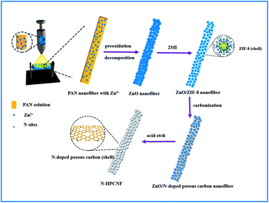
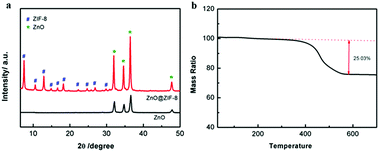
Fig. 1 illustrates the synthetic strategy of N-HPCNF materials. The synthesis consists of two steps: (i) formation of ZnO/ZIF-8 nabofibers and (ii) carbonization and removal of ZnO template core. ZnO nanofibers composed of compactly arranged ZnO particles subunits were first prepared by electrospinning using PAN and Zn(AC)2·2H2O solution as spinning fluid. Then they were mixed with 2MI. ZnO nanoparticles would release Zn2+ and react with 2MI for the surface growth of ZIF-8 shells. As a result, the ZnO nanoparticle subunits in the nanofiber would act as countless “nucleation centers” to pack the ZIF-8 shells into fibrous structure. After that, carbonization at high temperature was carried out to transform ZIF-8 shell into nitrogen doped porous carbon. Finally, the ZnO template cores were removed by acid etch and carbon nanofibers consisting of nitrogen doped hollow porous carbon shell subunits was obtained.The morphology and structure of as-prepared ZnO nanofiber and ZnO/ZIF-8 nabofibers is displayed in Fig. 2. As can be seen in Fig. 2a, ZnO nanofiber is about 600 nm in diameter. Compared with the electrospun CNF without the adding of Zn(AC)2·2H2O (Fig. S1†), the ZnO nanofibers have a highly rough surface, which indicates complete decomposition of PAN precursor during heat treatment. The corresponding TEM image (Fig. 2c) reveals that it is composed of closely spaced ZnO nanoparticles grown along with the fiber direction with a diameter of 100 nm. After reaction with 2MI, the external layers of the ZnO nanoparticles convert to ZIF-8 in priority. As a result, the original ZnO nanoparticles progressively grow smaller with ZIF-8 covering the surface, leading to a core–shell structure (the yellow circle in Fig. 2d). The XRD spectra also confirm the successful growth of ZIF-8 within the ZnO nanofiber for the resultant ZnO/ZIF-8 sample (Fig. 3a). The peaks at 7.2°, 10.9°, 12.7°, 14.4°, 16.56°, 17.9°, 23.8°, 26.3°, 29.0°, and 30.2° are attributed to (011), (002), (112), (022), (013), (222), (233), (134), (044) and (334) crystal planes of ZIF-8,20 respectively. In addition, the fibrous structure of initial ZnO nanofiber is well retained (Fig. 2b).
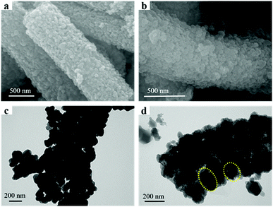 | ||
| Fig. 2 SEM and TEM images of as-prepared samples, (a) SEM images of ZnO nanofiber; (b) SEM images of ZnO/ZIF-8 nanofiber; (c) TEM images of ZnO nanofiber; (d) TEM images of ZnO/ZIF-8 nanofiber. | ||
Fig. 3b shows the TG curve of ZnO/ZIF-8 nabofibers. As depicted in Fig. 3b, the sample has a slight weight loss (25.03%) between 320 °C and 550 °C, corresponding to the decomposition of ZIF-8 shell, just as eqn (2) shows:
| 2C8H12N4Zn + 23O2 = 2ZnO + 16CO2 + 12H2O + 4N2 | (2) |
Therefore, in the case of our heat treatment at a temperature of 550 °C, the ZIF-8 shells are removed to generate ZnO residuum, while the ZnO cores are retained. According to eqn (2), the loading amount of ZIF-8 on the surface of ZnO nanoparticles could be acquired by calculation. The result shows the mass fraction of ZIF-8 is 38.96%, which guarantees a highly hollow porous structure after the removal of ZnO.
Fig. 4a shows the SEM images of N-HPCNF after carbonization of ZnO/ZIF-8 sample and removal of ZnO. It can be seen that the N-HPCNF sample retains the fiber-like morphology without apparent changes in appearance. In contrast with nitrogen doped porous carbon derived from ZIF-8 nanoparticle (Fig. S2†), the 1D fibrous structure could improve the electrical conductivity effectively. The detailed morphological and structural properties of the porous structure of N-HPCNF were further observed using TEM. Fig. 4b shows the typical TEM images, which highlights the porous feature of N-HPCNF.
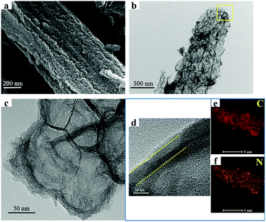 | ||
| Fig. 4 SEM and TEM images of N-HPCNF, (a) SEM images; (b) TEM images; (c) magnified TEM image; (d) HRTEM images; (e and f) elemental mapping images of C and N. | ||
The magnified TEM image of the selected area shown by the square frame in Fig. 4b demonstrates that N-HPCNF is composed of small hollow carbon shells, about 50–70 nm in diameter, which connect together to form a continuous fibrous structure (Fig. 4c). It is due to the closely packed ZnO nanoparticle template, just as above mentioned. Furthermore, the HRTEM image in Fig. 4d reveals that the carbon shells (about 8–10 nm in thickness) have a highly disordered porous structure with a large fraction of micropores. There are also some ordered lattice fringes in the carbon shells, revealing the graphitization nature to some extent. These TEM images reveals that N-HPCNF has a typical hierarchical porous characteristic, with the microporous shell and the macroporous hollow core. The former originates from the porous structure of ZIF-8, and the latter comes from the removal of ZnO core during the acid treatment. This unique structure could efficiently promote ion diffusion efficiency and ensure electrode infiltration by electrolyte. TEM mapping was also conducted to determine the distribution of elements. The results shown in Fig. 4e and f display the uniform distribution of C and N atoms through the porous structure.
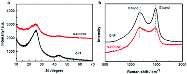
XRD was carried out to characterize the structure of N-HPCNF and contrast CNF samples. Both the samples show two broad peaks (Fig. 5a). The peaks at around 24.2° can be assigned to the (002) plane with an interlayer spacing of 0.36 nm, suggesting the amorphous nature of carbon.21 In comparison with CNF, the disordered degree of N-HPCNF is increased. It is further confirmed by Raman spectra in Fig. 5b. The D band at 1340 cm−1 is associated with disorder arising from structural defects, while the G band at 1580 cm−1 corresponds to the first-order scattering of the stretching vibrational mode E2g observed due to the sp2 bonded carbon domains.22 It is generally accepted that the relative intensity of signals at D band and G band illustrates the disordered degree of samples. Compared with the spectra of CNF, the ID/IG increased in the spectra of N-HPCNF, demonstrating the more disordered structure of N-HPCNF. It is attributed to the highly porous structure and the increased defects induced by the heteroatom doping.
The surface chemical compositions of the N-HPCNF and CNF sample are further investigated by XPS measurement. The XPS survey scan spectra in Fig. 6a show signals of C, O, and N elements for both of the two samples. Based on the XPS analysis, the atomic percentage of N in N-HPCNF and CNF is around 18.3% and 3.7%, respectively. Their N 1s spectra can be further fitted into three peaks separately, pyridinic N6 (398.4 eV), pyrrolic N5 (399.9 eV) and quaternary N (400.9 eV) for N-HPCNF, while pyrrolic N5 (399.9 eV), quaternary N (400.9 eV) and pyridine N-oxide (402.3 eV) for CNF, as presented in Fig. 6b and c. As previously reported, the N-6 nitrogen is produced predominately via substituting a carbon atom by nitrogen on the edges or defect sites of the graphitic carbon layer. This kind of nitrogen is considerably more chemically active with a low energy barrier. Furthermore, the N-6 nitrogen can induce a large number of defects, which serve as electrochemical active sites, hence improving the charge storage capacity for carbon materials.23 From quantitative analysis, the relative content of different kinds of nitrogen atoms in both samples is listed in Table S1.† It can be clearly observed that N-HPCNF has a much higher N-6 content up to 59.6%.
The porous structure of the N-HPCNF samples was obtained from N2 adsorption–desorption measurements. The isotherms exhibit a type IV characteristics, indicating the mesoporous structure (Fig. S3†). A specific surface area of about 484 m2 g−1 for N-HPCNF is obtained by the BET measurement. The corresponding pore size distribution curve (Fig. S3b†) shows that the size of the majority of the pores falls in the range of below 10 nm and 50–100 nm, verifying the hierarchical structure.
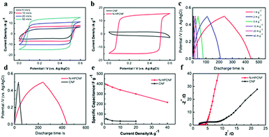
The as-prepared N-HPCNFs are then investigated as electrode materials for supercapacitors. Firstly, the electrochemical performance is tested in a three-electrode configuration using cyclic voltammetry (CV) and galvanostatic charge–discharge (GCD) measurements in 2 M KOH aqueous solution. Fig. 7a shows the CV curves of N-HPCNF at different scan rates ranging from 5 to 50 mV s−1, which are nearly rectangular-like in shape, indicating a characteristic capacitive behaviour as the electrodes of electrical double layer supercapacitors. In comparison, the CV integrated area of CNF is negligible as compared with those of the N-HPCNF (Fig. 7b), implying the much reduced capacitance. In addition, the GCD curves of N-HPCNF electrode at different current densities is also measured and the result is displayed in Fig. 7c. All the curves show good symmetry and nearly linear slopes, confirming the electric double-layer capacitance. The calculated specific capacitance for N-HPCNF at 1.0 A g−1 is as high as 394 F g−1, which is much higher than the electrode prepared from CNF (54 F g−1). It is in accordance with the CV results.
The electrochemical performance of ZIF-8 derived carbon was also analysed through CV and GCD techniques (Fig. S4†). Although ZIF-8 derived carbon shows similar rectangular CV curves, its capacitance is much reduced. The specific capacitance calculated from the GCD curve is only 184 F g−1, indicating the superior performance of N-HPCNF.
The gravimetric capacitance as a function of current density of N-HPCNF and CNF were calculated and summarized in Fig. 7e. When the discharge current densities gradually increase to 2.0, 5.0 10 and 20 A g−1, the specific capacitance decrease to 388, 370, 340 and 300 F g−1, with 76.1% capacitance retention. Even discharged at high current densities of 40 A g−1, the N-HPCNF retains a high specific capacitance of 216 F g−1, about 54.8% of the capacitance at 1.0 A g−1, highlighting excellent rate capability. Although the charge–discharge properties of CNF is similar to that of N-HPCNF, its rate performance is much worse, only 53.7% retention with the current density ranging from 1 to 20 A g−1.
The rate capability of N-HPCNF is superior to many of the previously reported carbon-based materials (Table S2†), especially 1D carbon structures, such as carbon nanotube, bubble carbon nanofibers, nitrogen and oxygen enriched hierarchical porous carbon fiber, and N-doped carbon bubbles/carbon tube arrays.24–26 We attributed it to its unique structure. Compared with traditional porous carbon nanofibers, N-HPCNF is composed of closely packed hollow porous carbon shell subunits. The numerous inner holes act as reservoir, which are able to shorten the ions diffusion distances and allow easier electrolyte transmission through the whole electrode material.
To further evaluate the advantages of the synthesized N-HPCNF, EIS measurements were conducted. The Nyquist plots and the equivalent circuit were shown in Fig. 7f and S5.† The plots consist of a semicircle at high frequencies in relation to the charge transfer resistance (Rct) followed by a straight line in the low frequency region in relation to the diffusive resistance (Warburg impendence, W). Compared to CNF, N-HPCNF has the smaller semicircle corresponding to lower Rct (1.021 Ω vs. 4.018 Ω), which demonstrates fast electron transfer through the electrode/electrolyte interface. At the same time, the slope of N-HPCNF show almost parallel to the imaginary axis at low frequencies, representing the low ionic resistance, which is a key parameter for the rate capability of the porous carbons.
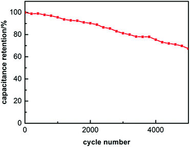
The cycle stability of the N-HPCNF electrode was explored at a constant charge and discharge current density of 10 A g−1 for 5000 cycles. As shown in Fig. 8, N-HPCNF retains almost 67.3% of their initial capacitance after 5000 cycles, indicating good cyclability.
The outstanding electrochemical performance of N-HPCNF may benefit from its unique features in structure and composition: (1) the hierarchical porous structure could effectively improve the surface area, and thus offer sufficient electrochemically active sites for electrolyte ion adsorption; (2) the numerous inner holes could promote electrolyte transmission and ensure the electrode fully wetted, which not only improve rate performance but also increase the utilization of electrode surface. (3) The 1D fiber-like morphology promotes ion/electron transport through the entire electrode. (4) The abundant nitrogen doping, especially N-6 doping, helps to alter the energy state of N-HPCNF and facilitates the electrochemical reaction.
Conclusions
In summary, a supercapacitor electrode material with excellent electrochemical performance has been fabricated by the combination of electrospinning and in situ growth of ZIF-8. Compared with traditional porous carbon nanofiber, the as-prepared N-HPCNF is composed of closely packed hollow porous carbon shell subunits, in which the numerous inner holes ensure rapid electrolyte transport over the entire electrode, leading to larger accessible surface area for charge adsorption. Moreover, the high nitrogen doping level further facilitates the electrochemical reaction. As a result, the N-HPCNF exhibits a high specific capacitance of 394 F g−1 at a current density of 1.0 A g−1 and excellent rate performance. After repetitive charge–discharge of 5000 cycles at a high current density of 10 A g−1, the N-HPCNF retains almost 67.3% of its initial capacitance. These results demonstrate that N-HPCNF is a promising electrode material for supercapacitor application.Conflicts of interest
There are no conflicts to declare.Acknowledgements
This work was financially supported by the Shandong Provincial Natural Science Foundation, China (grant no. ZR2019PB018).References
- T. Liu, F. Zhang, S. Yu and Y. Li, J. Mater. Chem. A, 2017, 5, 17705 RSC.
- H. Hu, Bu Y. Guan and X. W. Lou, Chem, 2016, 1, 102 CAS.
- Z. W. She, J. Kibsgaard, C. F. Dickens, I. B. Chorkendorff, J. K. Norskov and T. F. Jaramillo, Science, 2017, 355, 6321 Search PubMed.
- P. Simon and Y. Gogotsi, Nat. Mater., 2008, 7, 845 CrossRef CAS PubMed.
- J. Sun, W. Li, B. Zhang, G. Li, L. Jiang, Z. Chen, R. Zou and J. Hu, Nano Energy, 2014, 4, 56 CrossRef CAS.
- X. Liu, C. Shi, C. Zhai, M. Cheng, Q. Liu and G. Wang, ACS Appl. Mater. Interfaces, 2016, 8, 4585 CrossRef CAS PubMed.
- X.-C. Xie, K.-J. Huang and X. Wu, J. Mater. Chem. A, 2018, 6, 6754 RSC.
- Y. Li, Y. Zhang, H. Zhang, T. Xing and G. Chen, RSC Adv., 2019, 9, 4180 RSC.
- Q. Liao and C. Wang, CrystEngComm, 2019, 21, 662 RSC.
- G. A. Snook, P. Kao and A. S. Best, J. Power Sources, 2011, 196, 1 CrossRef CAS.
- M. Klose, R. Reinhold, K. Pinkert, M. Uhlemann, F. Wolke, J. Balach, T. Jaumann, U. Stoeck and J. E. L. Giebeler, Carbon, 2016, 106, 306 CrossRef CAS.
- J. L. Liu, L. L. Zhang, H. B. Wu, J. Y. Lin, Z. X. Shen and X. W. Lou, Energy Environ. Sci., 2014, 7, 3709 RSC.
- D. Pech, M. Brunet, H. Durou, P. H. Huang, V. Mochalin and Y. Gogotsi, et al., Nat. Nanotechnol., 2010, 5, 651 CrossRef CAS.
- K. A. Cychosz, R. Guillet-Nicolas, J. García-Martínez and M. Thommes, Chem. Soc. Rev., 2017, 46, 389 RSC.
- M. Jiang, X. Cao, D. Zhu, Y. Duan and J. Zhang, Electrochim. Acta, 2016, 196, 699 CrossRef CAS.
- P. Zhang, F. Sun, Z. Xiang, Z. Shen, J. Yun and D. Cao, Energy Environ. Sci., 2014, 7, 442 RSC.
- L. J. Xin, R. R. Chen, Q. Liu, J. Y. Liu, Z. S. Li, R. M. Lia and J. Wang, New J. Chem., 2017, 41, 12835 RSC.
- W. Zhang, Z.-Y. Wu, H.-L. Jiang and S.-H. Yu, J. Am. Chem. Soc., 2014, 136, 14385 CrossRef CAS PubMed.
- W. Zhan, Q. Kuang, J. Zhou, X. Kong, Z. Xie and L. Zheng, J. Am. Chem. Soc., 2013, 135, 1926 CrossRef CAS.
- Y. Mao, G. Li, Y. Guo, Z. Li, C. Liang and X. Peng, et al., Nat. Commun., 2017, 8, 14628 CrossRef.
- Y. Liu, G. Li, Z. Chen and X. Peng, J. Mater. Chem. A, 2017, 5, 9775 RSC.
- J. Zhang, Y. Yu, L. Liu and Y. Wu, Nanoscale, 2013, 5, 3052 RSC.
- D. Nan, Z. H. Huang, R. Lv, L. Yang, J.-G. Wang and W. Shen, et al., J. Mater. Chem. A, 2014, 2, 19678 RSC.
- J. Sheng, C. Ma, Y. Ma, H. Zhang, R. Wang and Z. Xie, et al., Int. J. Hydrogen Energy, 2016, 41, 9383 CrossRef CAS.
- H. Zhao, W. Han, W. Lan, J. Zhou, Z. Zhang, W. Fu and E. Xie, Electrochim. Acta, 2016, 222, 1931 CrossRef CAS.
- Z. Tang, G. Zhang, H. Zhang, L. Wang, H. Shi, D. Wei and H. Duan, Energy Storage Materials, 2018, 10, 75 CrossRef.
Footnote |
| † Electronic supplementary information (ESI) available: SEM images of CNF, ZIF-8 and ZIF-8 derived N doped porous carbon; detail breakdown of N 1s signal; N2 adsorption/desorption isotherms of N-HPCNF; electrochemical performance of ZIF-8 derived carbon; summary of the rate performance of some carbon electrodes. See DOI: 10.1039/c9ra07846k |
| This journal is © The Royal Society of Chemistry 2019 |

