 Open Access Article
Directional and velocity control of active droplets using a rigid-frame†
Masato Yamada *a,
Hiroki Shigemune
 b,
Shingo Maedab and
Hideyuki Sawadaa
aDepartment of Applied Physics, School of Advanced Science and Engineering, Waseda University, 3-4-1 Okubo, Shinjuku-ku, Tokyo, 169-8555, Japan. E-mail: yamada@sawada.phys.waseda.ac.jp
bDepartment of Engineering Science and Mechanics, School of Engineering, Shibaura Institute of Technology, 3-7-5 Toyosu, Koto-ku, Tokyo, 135-8548, Japan
First published on 6th December 2019
Abstract
This paper introduces a novel directional control method of self-propelled oil droplets. Oil droplets locomote spontaneously with surfactant action. This self-propulsion is caused by Marangoni convection within the oil droplet due to differences in the surfactant concentration at the droplet surface. Recent studies have reported that self-propelled oil droplets change their locomotion style depending on their shapes. We confirm that spherical oil droplets move randomly, including straight motion, bending motion, and rotation. In particular, we discover that boomerang-shaped oil droplets exhibit only straight motion. In this study, we introduce an exoskeleton for the directional and velocity control of oil droplets. A droplet shaped as a boomerang by an exoskeleton locomotes in the direction from a concave region to a convex region. Through experimental studies, we found that the stability of the velocity and locomotion direction depended on the boomerang shape. Self-propelled oil droplets with exoskeletons were then applied to a transporting robot driven only by the energy obtained from chemical reactions. We demonstrate the robot pushes and transports an object floating on water.
Introduction
Living things locomote by utilizing energy derived from chemical reactions and by employing unique mechanisms combining hard and soft materials. For example, humans actuate muscles using chemical energy obtained from the decomposing reaction of adenosine triphosphate (ATP)1–5 and realize dynamic and dexterous soft muscle movement restricted by the hard skeleton and tendons.6–10 Recently, the use of chemical reactions in locomotion has been extended to robotics.11,12 In particular, Maeda et al. developed a self-walking gel robot driven by an oscillatory Belousov–Zhabotinsky (BZ) reaction,11 while Wehner et al. developed an octopus-like, autonomous robot based on an oscillating microfluidic network actuated by pressure from decomposing reaction of hydrogen peroxide.12 These electronics-less robots have high autonomy because the materials and reactions in the robot act as both the energy source and the controller. However, the mobility of these robots is still severely limited. For example, the mobility of the self-walking gel robot depends on its external environment, while the octopus like robot is fixed on a floor.We have focused on the mechanisms combining hard and soft materials that are unique to biological organisms,13–16 and have developed a new control method by combining chemical reactions with these mechanisms. In this research, we examine self-propelled oil droplets,17–30 and apply an exoskeleton to a self-propelled droplet for the controllable droplet locomotion. Additionally, we exploit the controllability of the exoskeleton to develop a milli-size transporter on water. In the proposed system, the oil droplets fulfill the function of the actuator together with the exoskeleton.
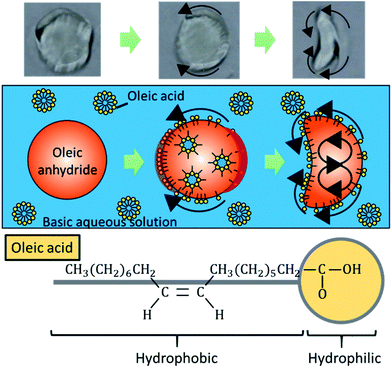
Self-propelled oil droplets locomote in water due to the effect of solutal Marangoni convection.31–34 Fig. 1 shows the propulsion mechanism for a droplet in water, together with the chemical formula of oleic acid. As shown in the formula, the oleic acid is a surfactant, which has a hydrophilic group and a hydrophobic group. When an oil droplet is placed into an aqueous surfactant solution, the surfactant adsorbs to the oil droplet. A gradient in the concentration of the surfactant is generated at the interface between the droplet and the aqueous solution. Differences in the concentration gradient lead to differences in the surface tension of the droplet, which causes Marangoni convection to occur inside the droplet body. Then, an anhydride of the surfactant, which exists inside the oil droplet, is hydrolyzed at the interface. The adsorption and desorption of oleic acid is locally active in the surface, since the droplet is locomoting in the direction from the concave region to the convex region. The adsorption of oleic acid is active at the tip of the convex region of the self-propelled oil droplet, on the other hand the desorption of oleic acid is active at the tip of the concave region, by considering the moving direction. As a result, the greater gradient of the concentration of oleic acid occurs at the boundary of the convex region in the boomerang-shaped oil droplets, and a gentle concentration gradient occurs in the concave regions (please refer to Fig. S1†). Therefore, this adsorption and desorption of oleic acid maintain the convection inside the droplets. Finally, stable flow occurs in a certain direction at the droplet–aqueous solution interface, and the oil droplet is propelled because of this flow.17 We have confirmed this phenomenon by a simple experiment for visualizing the internal flow using small colloidal particles. Since the internal flow in a round-shaped oil droplet initially occurs randomly, the propulsion direction is stochastic. In addition, we investigated the induction time until the oil droplet starts to move under different basic conditions to support the mechanism. Table 1 summarizes the measurement results of the induction time in three basic conditions.
| pH | Induction time [s] |
|---|---|
| 11.0 | 7.6 |
| 11.5 | 6.2 |
| 12.0 | 3.7 |
In our previous research, motion control was developed for a self-propelled oil droplet by utilizing flow channels.35 The locomotion of the droplet was controlled by changing the course of the flow channels, but the droplets propelled randomly in open systems. In this study, we propose a method for controlling the motion of oil droplets by fitting a hard exoskeleton to the soft active matter. The hard exoskeleton alters the concentration gradient of the surfactant at the interface by providing boundary conditions for the oil droplet. We further exploit the proposed chemical robot by utilizing the active matter to transport objects floating on water.
Preliminary experiment
Random motion of self-propelled oil droplet
As described above, the direction of internal flow in the droplet will occur randomly; thus, the direction of the propulsion will also be random in some cases. We conducted a preliminary experiment to confirm the randomness in the locomotion of self-propelled oil droplets using a simple experimental set up with both oil and aqueous phases. Oleic anhydride and nitrobenzene were mixed to make the oil phase, and the aqueous phase was prepared by mixing oleic acid (surfactant) with an aqueous solution adjusted to pH 12 with sodium hydroxide. A 7 cm diameter dish was filled with 3.5 mL of the prepared aqueous solution. The oil was dropped in the center of the dish with a micropipette in volumes ranging from 1 μL to 10 μL in 1 μL increments. The experiment was repeated seven times for each volume. The movement of the droplet was recorded for approximately 50 s, and we used movie analysis software (Kinovea) to measure the movement of the oil droplet. Fig. 2(a) and (b) show the self-propulsion of the 2 μL and 8 μL oil droplets. Note that the 2 μL droplet did not split (Fig. 2(a)); however, the 8 μL droplet split into three separate droplets, and each droplet locomoted in different directions (Fig. 2(b)). As expected, the oil droplets stochastically repeated various movements such as straight locomotion, bending motion, rotation, stop, and division. The movements ceased when the anhydride of the surfactant inside the oil droplet was completely hydrolyzed.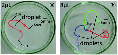 | ||
| Fig. 2 Locomotion of (a) 2 μL and (b) 8 μL self-propelled droplets without rigid-frame. Large amount of oil droplets break up into small pieces. | ||
Locomotion of self-propelled oil droplet without exoskeleton
To examine the fundamental behavior of the droplets, we further analyzed the movement and velocity of self-propelled droplets in the experiment described above. We extracted the average velocity of the droplet during the first 3 seconds of stable self-propulsion, as shown in Fig. 3. In the case of an example shown in Fig. 3, the velocity of the poured oil droplet converged after approximately 4 seconds. This is because it takes time for the internal convection of the oil droplets to stabilize after the flow field is generated inside the oil droplets. Since the time to stabilize the locomotion varies depending on the samples, the time to start extracting the velocity is changed in the experiments.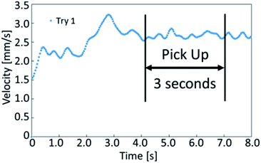 | ||
| Fig. 3 The graph shows the velocity of a self-propelled droplet. We selected the stable period for 3 seconds while locomoting to determine the average velocity. | ||
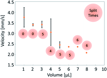
Fig. 4 shows a comparison of the droplet average velocity and splits. The 1 μL and 2 μL oil droplets did not split in the aqueous solution. The 3 μL to 8 μL oil droplets split into smaller droplets in several attempts, and the 9 μL and 10 μL oil droplets split in all attempts. To confirm this behavior, the 10 μL oil droplet was tested a total of 24 times, and the oil droplets split in all the attempts (ESI Table S1† summarizes these data). When the droplet was split we selected the largest fraction from the divided droplets for the analysis.
The 1 μL droplet demonstrated an average velocity of 3.76 mm s−1 over seven attempts, whereas the largest 10 μL oil droplet demonstrated a velocity of 2.15 mm s−1. The velocity of the oil droplets decreased as the oil droplet volume increased. An oil droplet with large volume has a large surface area, and the driving force becomes greater. Simultaneously, the oil droplet spreads in the direction that is perpendicular to the locomoting direction as the volume increases, which results in the increase of viscous resistance. Since the influence of viscous resistance becomes large, the velocity of the oil droplet decreases as the volume increases. The effects of the volume and the viscous resistance are considered to works as counterbalance with each other.
Proposed method
Directional control mechanism of self-propelled oil droplet
When the oil droplet showed straight motion, we observed a boomerang shape, and the direction of motion was parallel to the line from the convex region to the concave region, as shown in Fig. 1. This fact has been widely observed and simulated numerically.36–41 Nagai et al. proposed that the concentration gradients of pentanol (alcohol) occur at interfaces between alcohol droplets and the low pentanol concentration aqueous phase.41 The concentration gradient of pentanol is different in the convex and concave regions of the boomerang shape. These differences in concentration gradients lead to differences in interfacial tension. Thus, the droplets locomote straightly in the direction from the concave to convex region while maintaining their boomerang shape. Referring to the interfacial tension difference between the convex region and the concave region theorized by Nagai et al., we extend the theory to the locomotion of a pentanol oil droplet by considering the similar interfacial tension difference.In the oil droplet utilized in our experimental environment, oleic acid (surfactant) is generated from oleic anhydride at the oil–water interface by a hydrolysis reaction. Oleic acid (surfactant) is amphiphilic similar to pentanol (alcohol), and the concentration of oleic anhydride inside the droplets is 50 times higher than that of oleic acid in the aqueous phase in our droplet system. Therefore, we assume that the dynamics of oleic acid (surfactant) is the identical to that of pentanol (alcohol), and the concentration gradients of oleic acid occur at the oil–water interfaces similar to the case of pentanol. Fig. S1† shows the concentration gradients of the surfactant at the oil–water interfaces in the oil droplet system. The absolute value of the concentration gradients is higher at the convex region than that at the concave region in boomerang shape of the oil droplet.41,42 By considering the concentration gradients, the interfacial tension difference between the convex and concave regions in the boomerang shape Δγ is given as
 | (1) |
 the interfacial tension difference Δγ is positive (Δγ > 0). This interfacial tension difference generates a pair of convection as shown in Fig. 1. Then, oil droplets continue to locomote in the direction from the concave to convex region by maintaining their boomerang shape. Herein, we utilize this theory of locomotion to propose a novel method for installing a boomerang-shaped exoskeleton on self-propelled oil droplets in order to ensure straight motion. Directional control of the self-propelled oil droplet can be maintained by using the exoskeleton to preserve the droplet's shape. The exoskeleton further prevents large volume oil droplets from dividing into smaller droplets. Larger oil droplet volumes exert larger driving forces that are advantageous in robotics applications.
Locomotion of self-propelled oil droplet with exoskeleton
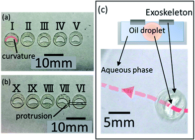
Next, we conducted an experiment with exoskeletons (ESI Movie 1†). To determine the optimal boomerang shape for the exoskeletons, we prepared 10 exoskeletons by cutting different internal shapes using 0.1 mm-thick overhead projector (OHP, polyester) film (ESI Fig. S2† shows the schematic diagram of these exoskeletons, and Table S2† summarizes the details of the 10 types of exoskeletons). In five exoskeletons (I–V), the convex regions of the boomerang shape have different curvatures (Fig. 5(a)). In the other five exoskeletons (VI–X), the concave regions of boomerang shape have different protrusions (Fig. 5(b)). The size was adjusted so that the area of the exoskeleton was fixed at 37.7 mm2. The outer shape of all exoskeletons was made circular to ensure that the viscous resistance was uniform for every exoskeleton.Similarly, to the experiment without exoskeletons, we placed 3.5 mL of the aqueous solution in a 7 cm dish. We floated the exoskeleton on the aqueous solution, and 10 μL of the oil was dropped inside the exoskeleton. We observed the oil droplet velocity over seven attempts, and only the trials satisfying the following conditions were measured and recorded: (a) self-propelled oil droplets completely filled the interior of the exoskeleton, and (b) oil droplets locomoted from the center of the Petri dish to the wall. Fig. 5(c) shows an example locomotion trajectory of the droplet with exoskeleton X, which has a convex region with 0.0306 mm−1 curvature and a concave region with 0.302 mm protrusion (see ESI Fig. S3† for exoskeleton details). As described in eqn (1), surface tension differences occur between the convex and concave regions in the boomerang-shaped exoskeleton. Therefore, self-propelled droplets with exoskeletons should locomote in the direction from the concave region to the convex region. The 10 μL oil droplet with exoskeleton X showed an average velocity of 2.69 mm s−1 over seven attempts. In other words, the 10 μL droplets with an exoskeleton were 0.54 mm s−1 faster than those without. Moreover, splitting of the droplet was suppressed, which has the advantage of producing higher power for utilization as a robot. Thus, the internal shape of the exoskeleton preserves the shape of the droplet and reduces fluidic resistance.
Result and discussion
Evaluation on velocity
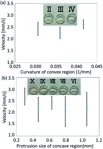
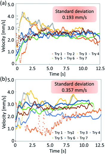
In the experiments, we analyzed the velocity change of self-propelled oil droplets fitted with exoskeletons. As a result of applying conditions (a) and (b), exoskeleton I and exoskeleton V were excluded from the results because the oil droplets did not fill the exoskeleton due to their surface tension. Fig. 6(a) and (b) show the average velocity of oil droplets fitted with eight remaining exoskeletons. These exoskeletons were classified into two groups: one group of three types having different curvatures of the convex region (Fig. 6(a)), and the other group of five types having different protrusions of the concave region (Fig. 6(b)). The error bars of the graph show the standard deviation over seven experiments. Droplets fitted with exoskeletons IV and X demonstrated the largest velocity in each category.We compared exoskeleton IV and exoskeleton X to further investigate the exoskeleton design. Fig. 7(a) shows the velocity of the droplets fitted with exoskeleton IV, and the average velocity was 2.61 mm s−1, which was the largest velocity among exoskeletons I–V. Fig. 7(b) shows the velocity of the droplets fitted with exoskeleton X, and the average velocity was 2.69 mm s−1, which was the highest velocity among exoskeletons VI–X. As shown in Fig. 7(a) and (b), the variation in the velocity was quite different between exoskeletons IV and X. The standard deviation of the average velocity was 0.193 mm s−1 and 0.357 mm s−1 for exoskeletons IV and X, respectively. The stability of exoskeleton IV was also clearly shown in the obtained graphs.
We developed a mathematical model to calculate the driving force. An object in a viscous fluid follows the following equation of motion:
 | (2) |
When the oil droplet was assumed to have a spherical shape and zero acceleration, the driving force F can be derived by eqn (2):
| F = 6πηa〈v〉 | (3) |
Evaluation on directional control
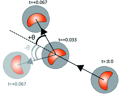
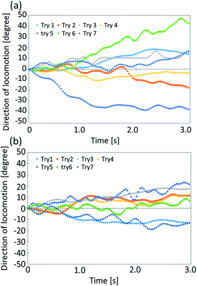
We further analyze the stability in angular motion for exoskeletons IV and X. Self-propelled oil droplets without the exoskeletons locomote randomly, and do not show stable straight locomotion. Therefore, we do not compare the stability of the angular change during the locomotion of the self-propelled oil droplet without an exoskeleton. The calculation of the angular direction of a droplet with an exoskeleton is shown in Fig. 8(a). Using the same procedure as that for measuring the velocity change, we focused on 3 seconds of stable droplet motion and calculated the change in the angle between each image frame. Fig. 9(a) and (b) show the direction of locomotion of the two self-propelled oil droplets fitted with exoskeletons IV and X, respectively. We found a remarkable difference in the traveling direction after 3 seconds. The standard deviation in the traveling direction after 3 seconds was 24.6° for exoskeleton IV and 13.2° for exoskeleton X. From these results, the oil droplet fitted with exoskeleton X showed more stable directional motion than exoskeleton IV.Our experimental verification of the stability of exoskeletons IV and X showed higher velocity stability in exoskeleton IV and higher directional stability in exoskeleton X. Exoskeleton IV has a more circular interior shape than exoskeleton X. If the shape inside the exoskeleton is close to a circle (spherical), the oil droplet tends to have more random behavior. However, the resistance from the aqueous solution during self-propulsion tends to be constant from all directions for more spherical shapes. Therefore, the oil droplets fitted with exoskeleton IV have small variations in average velocity, and those fitted with exoskeleton X have small variations in the traveling direction (as described in ESI Fig. S4†).
Demonstration as a transporter
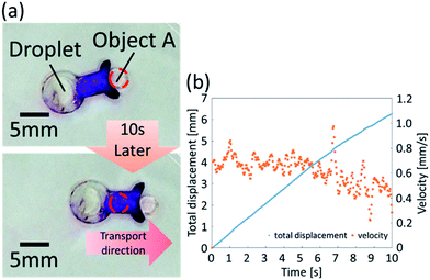
We then utilized the droplets with exoskeletons to demonstrate a waterborne transport robot driven by chemical reaction. We designed a beetle-shaped exoskeleton to push an object floating on water. In order to transport an object precisely, the directional control is more important than velocity. In addition, the differences of driving force are small among different shapes of the boomerang shape. Therefore, we developed a beetle-shaped transport robot based on exoskeleton X and demonstrated an experimental drug delivery system using the exoskeleton. We used colored vegetable oil to represent object A. The waterborne transport robot successfully transported the object 6.26 mm in 10 s at an average velocity of 0.61 mm s−1, as shown in Fig. 10(a) and (b) (ESI Movie 2†). The biocompatibility of the proposed oil droplets is low, however we consider that the biocompatibility can be improved by wrapping oil droplets with a gel film.22Experimental setup
Materials
The oil phase was prepared as follows. First, 141 μL oleic anhydride (Sigma-Aldrich) was mixed with 252 μL nitrobenzene (Kanto Chemical) using a magnetic stirrer (AS ONE, RS-6AN). We used between 1–10 μL oil in each experiment.The aqueous phase was prepared as follows. First, 100 mL of pure water was basified to pH 12 using sodium hydroxide (Kanto Chemical). Next, 317 μL oleic acid (Wako) was mixed into the aqueous solution.
Oil droplet motion
To observe the oil droplet motion, 3.5 mL the aqueous phase solution was poured into a Petri dish with a 7 cm diameter (SANSHO, 75 × 21) using a micropipette (TGK, FPN-1000). Oil droplets were dropped onto the Petri dish from directly above using a micropipette (TGK, FPN-20).Preparing the exoskeleton
The shapes of the exoskeletons were designed with illustrator (Adobe Creative Cloud). The OHP with the 0.1 mm thickness film was cut with a cutting plotter (GRAPHTEC, T407A378426) and double bonded with superglue (ALTECO, 1712F).Exoskeleton experiments
The exoskeleton floats on the prepared aqueous solution in the center of the Petri dish (SANSHO, 75 × 21). For each experiment, 10 μL of the prepared oil was dropped inside the exoskeleton from directly above with the micropipette (TGK, FPN-1000). The droplets were measured using a single-lens reflex camera (CANON, EOS 70D) and analyzed by Kinovea. (Temperature: 299 K, humidity: 65%.) The viscosity of the aqueous solution was measured with a viscometer (AND, SV-10).Waterborne transport robot evaluation
Object A was prepared as follows. Vegetable oil (Nisshin) was dyed using red ink (Teranishi Chemical Industry). The beetle-shaped exoskeleton was prepared as follows. The OHP film with the 0.1 mm thickness was cut into a beetle shape and then double bonded with superglue. The boomerang shape was formed based on exoskeleton X. The tip was dyed with purple ink (ZEBRA) to make the transport clear. For the transport experiment, 10 μL colored vegetable oil was floated at the center of a Petri dish, and the beetle-shaped exoskeleton was floated on the aqueous phase. Then, a 10 μL self-propelled oil droplet was dropped on the boomerang region, and the transportation experiment was executed. The waterborne object transportation was measured with a video camera (SONY, HDR-CX675) and analyzed by Kinovea.Conclusions
We have realized the novel directional control of a self-propelled oil droplet using an exoskeleton. The exoskeleton was utilized to change the shape of the self-propelled oil droplets in order to produce certain motion behavior. Oil droplets deformed into the boomerang shape locomoted rectilinearly in the direction from the concave region to the convex region. Finally, oil droplets with a more circular boomerang shape had smaller directional stability and greater stability in velocity. We further demonstrated the use of self-propelled oil droplets fitted with an exoskeleton as waterborne transport robots. Because the locomotion of the oil droplet is based on the internal convection sustained by chemical reactions, we do not have to supply external energy, and this robot design can contribute to the development of chemical robotics. The demonstrated robots can operate in severe conditions such as that caused by a high pH aqueous solution, as the hydrolysis of oleic anhydride is active under high pH. Self-propelled oil droplets with exoskeletons also have similar benefits to the locomotion style of living things that combine the mechanisms of soft and hard materials. If the exoskeleton is changed to deformable material, the locomotion direction of the self-propelled droplet could be manipulated and controlled more freely. In these ways, droplets with exoskeletons combine chemical robotics with biological mechanisms, which could lead to the creation of robots with more subtle and dexterous movements specific to living things.Conflicts of interest
There are no conflicts to declare.Acknowledgements
M. Y. performed all experiments and wrote the manuscript. H. S. setup the experiment and wrote the manuscript. S. M. and H. S supervised the project. All authors discussed the result. This paper is a part of the outcome of research performed under a Waseda University Grant for Special Research Projects (Project number: 2019C-249). We all thank JSPS for their support under Grants-in-Aid for Scientific Research on Innovative Areas (Research in a proposed research area) 18H05473, and under Grant-in-Aid for Challenging Exploratory Research 19K21950.References
- E. Eisenberg and T. L. Terrell, Science, 1985, 227, 999–1006 CrossRef CAS PubMed.
- D. J. Taylor, P. Styles, P. M. Matthews, D. A. Arnold, D. G. Gadian, P. Bore and G. K. Radda, Magn. Reson. Med., 1986, 3, 44–54 CrossRef CAS PubMed.
- S. P. Bessman and P. J. Geiger, Science, 1981, 211, 448–452 CrossRef CAS PubMed.
- M. L. Blei, K. E. Conley and M. J. Kushmerick, J. Physiol., 1993, 465, 203–222 CrossRef CAS PubMed.
- A. Noma, Nature, 1983, 305, 147–148 CrossRef CAS PubMed.
- L. Modenese, E. Montefiori, A. Wang, S. Wesarg, M. Viceconti and C. Mazza, J. Biomech., 2018, 73, 108–118 CrossRef PubMed.
- B. J. Fregly, T. F. Besier, D. G. Lloyd, S. L. Delp, S. A. Banks and M. G. Pandy, J. Orthop. Res., 2012, 30, 503–513 CrossRef PubMed.
- P. H. Veltink, H. J. Chizeck, P. E. Crago and A. EI-Bialy, IEEE Trans. Biomed. Eng., 1992, 39, 368–380 CrossRef CAS PubMed.
- J. E. Gregory and U. Proske, J. Physiol., 1979, 295, 251–262 CrossRef CAS PubMed.
- A. Arampatzis, G. D. Monte, K. Karamanidis, G. M. Klapsing, S. Stafilidis and G.-P. Bruggemann, J. Exp. Biol., 2006, 209, 3345–3357 CrossRef PubMed.
- S. Maeda, Y. Hara, T. Sasaki, R. Yoshida and S. Hashimoto, Adv. Mater., 2007, 19, 3480–3484 CrossRef CAS.
- M. Wehner, R. L. Truby, D. J. Fitzgerrald, B. Mosadegh, G. M. Whitesides, J. A. Lewis and R. J. Wood, Nature, 2016, 536, 451–455 CrossRef CAS PubMed.
- S. Wakimoto, K. Suzumori and T. Kanda, IEEE/RSJ International Conference on Intelligent Robots and Systems, 2005 Search PubMed.
- S. Wakimoto, K. Suzumori and J. Takeda, IEEE/ASME International Conference on Advanced Intelligent Mechatronics (AIM), 2011 Search PubMed.
- M. Mori, K. Suzumori, S. Wakimoto, T. Kanda and M. Takahashi, IEEE International Conference on Robotics and Automation, Anchorage, 2010 Search PubMed.
- M. Mori, K. Suzumori, M. Takahashi and T. Hosoya, Adv. Robot., 2010, 24, 233–254 CrossRef.
- M. M. Hanczyc, T. Toyota, T. Ikegami, N. Packard and T. Sugawara, J. Am. Chem. Soc., 2007, 129, 9386–9391 CrossRef CAS PubMed.
- N. Magome and K. Yoshikawa, J. Phys. Chem., 1996, 100, 19102–19105 CrossRef CAS.
- Y. Sumino, N. Magome, T. Hamada and K. Yoshikawa, Phys. Rev. Lett., 2005, 94, 068301 CrossRef PubMed.
- Y. Sumino, H. Kitahata, H. Seto and K. Yoshikawa, Soft Matter, 2011, 7, 3204–3212 RSC.
- F. Caschera, S. Rasmussen and M. M. Hanczyc, ChemPlusChem, 2013, 78, 52–54 CrossRef CAS.
- A. Suzuki, S. Meada, Y. Hara and S. Hashimoto, IEEE/RSJ International Conference on Intelligent Robots and Systems, 2012 Search PubMed.
- Y. Natsume and T. Toyota, Chem. Lett., 2013, 42, 295–297 CrossRef CAS.
- T. Banno and T. Toyota, Langmuir, 2015, 31, 6943–6947 CrossRef CAS PubMed.
- T. Banno, R. Kuroha, S. Miura and T. Toyota, Soft Matter, 2015, 11, 1459–1463 RSC.
- T. Ban, T. Yamagami, H. Nakata and Y. Okano, Langmuir, 2013, 29, 2554–2561 CrossRef CAS PubMed.
- S. Miura, T. Banno, T. Tonooka, T. Osaki, S. Takeuchi and T. Toyota, Langmuir, 2014, 30, 7977–7985 CrossRef CAS PubMed.
- T. Ban, A. Aoyama and T. Matsumoto, Chem. Lett., 2010, 39, 1294–1296 CrossRef CAS.
- L. Wang, B. Yuan, J. Lu, S. Tan, F. Liu, L. Yu, Z. He and J. Liu, Adv. Mater., 2016, 28, 4065–4070 CrossRef CAS PubMed.
- S. Kaneko, K. Asakura and T. Banno, Chem. Commun., 2017, 53, 2237–2240 RSC.
- H. Kim, K. Muller, O. Shardt, S. Afkhami and H. A. Stone, Nat. Phys., 2017, 13, 1105–1110 Search PubMed.
- H. Kim, F. Boulogne, E. Um, I. Jacobi, E. Button and H. A. Stone, Phys. Rev. Lett., 2016, 116, 124501 CrossRef PubMed.
- M. Wegener and A. R. Paschedag, Int. J. Multiphase Flow, 2011, 37, 76–83 CrossRef CAS.
- M. Wegener, Int. J. Heat Mass Transfer, 2014, 71, 769–778 CrossRef.
- A. Suzuki, S. Maeda, Y. Hara and S. Hashimoto, IEEE 27th International Conference on Micro Electro Mechanical Systems (MEMS), 2014 Search PubMed.
- K. H. Nagai, K. Tachibana, Y. Tobe, M. Kazama, H. Kitahata, S. Omata and M. Nagayama, J. Chem. Phys., 2016, 144, 114707 CrossRef PubMed.
- J. Lobert, F. Ziebert and I. S. Aranson, Sci. Rep., 2015, 5, 9127 CrossRef PubMed.
- F. Ziebert and I. Aranson, npj Comput. Mater., 2016, 2, 16019 CrossRef.
- B. Winkler, I. S. Aranson and F. Ziebert, Phys. D, 2016, 318–319, 26–33 CrossRef.
- J. Lober, F. Ziebert and I. S. Aranson, Soft Matter, 2014, 10, 1365–1373 RSC.
- K. Nagai, Y. Sumino, H. Kitahata and K. Yoshikawa, Phys. Rev. E: Stat., Nonlinear, Soft Matter Phys., 2005, 71, 065301 CrossRef PubMed.
- S. Nakata, Y. Iguchi, S. Ose, M. Kuboyama, T. Ishi and K. Yoshikawa, Langmuir, 1997, 13, 4454–4458 CrossRef CAS.
Footnote |
| † Electronic supplementary information (ESI) available. See DOI: 10.1039/c9ra07789h |
| This journal is © The Royal Society of Chemistry 2019 |

