DOI:
10.1039/C9RA07685A
(Paper)
RSC Adv., 2019,
9, 39230-39241
Long-term stably dispersed functionalized graphene oxide as an oil additive
Received
22nd September 2019
, Accepted 13th November 2019
First published on 29th November 2019
Abstract
In oil lubrication systems, it is essential to continuously supply lubricant to the contact surface during practical applications. Herein, to realize its long-term stable dispersion in oil, graphene oxide was modified with polyisobutylene succinimide (PIBS, trade name T154), which is an effective dispersant for lubricating oils. Characterization of the T154-modified graphene oxide (GO-T154) by FTIR, XPS, and XRD revealed that the surface of the graphene platelets was covered by the T154 chains, and the dimensions of the graphene platelets had obviously decreased. The dispersion study demonstrated the long-term stability of a GO-T154/oil suspension, which could stand for more than a year without any significant precipitation. The lubricating property was greatly improved by the addition of GO-T154; more specifically, for the optimal performance, the friction coefficient decreased by 54%, and the wear rate decreased by 60%. Micro observation of the worn surfaces indicated that well-dispersed GO-T154 could enter the gap between the friction surfaces, forming a transfer film to separate the rubbing surface. With the long-term stability, high thermal stability and outstanding tribological properties of the suspension, GO-T154 promises to realize practical applications of graphene in lubricating oil.
1. Introduction
Over the past decade, graphene platelets had received substantial attention from tribology researchers due to their nanoscale layer structure and superior properties.1–4 Graphene possesses a nanoscale laminated structure, high mechanical strength and thermal conductivity, making it quite suitable as a lubricant additive for lubricating oils.5,6 Compared with traditional additives, graphene has a higher loading capacity, thermal conductivity, and thermostability and is more eco-friendly. A variety of studies on graphene dispersed in base oils have been reported for improving lubricating and antiwear properties.7–15 Lin7 prepared modified graphene as oil additive, which greatly improved the tribological properties at a low concentration. Varrla Eswaraiah reported8 graphene modified by focused solar radiation, which enhanced lubricating, antiwear and extreme pressure properties of oil. In a report by Zhang et al.,9 0.02 wt% modified graphene reduced the friction coefficient and wear scar diameter by 17% and 14%, respectively. Oleic-acid-capped graphene oxide studied by Chen10 also showed excellent lubricating and antiwear properties in oil. All these studies have shown that with suitable treatment, graphene platelets in oil can form transfer film between friction surface to improve lubricating and antiwear properties. However, aggregation during long-term storage is a major problem for the real application of ultrafine particle additives such as graphene in lubricating oils owing to the strong interlayer interaction.16 This aggregation results in inhomogeneity of oil, leads to unstable tribological properties, and even worse, might plug the lubrication system. To homogeneously disperse graphene in base oil, covalently functionalized GO with a long organic chain was an effective method. Oleic acid and stearic acid are commonly used modifiers for graphene to improve its dispersity.7,9,10 Nevertheless, most of the commonly used modifiers were not effective for the long-term dispersity of graphene. Moreover, since these modifiers are micromolecular, they tend to decompose under friction heat during friction process. In the oil lubrication field, polyisobutylene succinimide (PIBS) is a high-quality ashless dispersant. Due to its good detergency and dispersity, it can inhibit the formation of carbon deposits on the pistons of engines. As a polymeric surfactant, it possesses a high thermostability and high capacity to improve the dispersity of inorganic particles with large particle sizes. Therefore, PIBS could theoretically improve the long-term dispersity of graphene and enhance its thermostability under friction heat.17
In this work, high molecular weight succinimide (polyisobutylene succinimide, PIBS, trade name T154), with a molecular weight of 1000, was used to modify graphene oxide. This modifier greatly improved the thermostability and dispersion stability of the graphene additive. At the same time, the modified graphene oxide decreased the wear rate of oil by more than 60%, and the coefficient of friction was reduced by 54%, implying that T154 modified GO was suitable for practical applications as a lubricating oil additive.
2. Experimental
2.1. Materials
GO was prepared by Beijing institute of aeronautical materials using Hummer's method.18 Absolute alcohol (analytical reagent, AR), petroleum ether (90–120 °C, AR), and n-heptane (AR) were obtained from Sinopharm Chemical Reagent Corporation. Polyisobutylene succinimide (PIBS, trade name T154), with molecular weight of 1000 was provided by Jinzhou Runda Chemical Co., Ltd. Polyalphaolefin-4 (PAO4) with a viscosity of 3.9 cps at 100 °C was purchased from Exxon Mobil Corporation.
2.2. Material preparation
As the precursor materials for modification, graphene oxide (GO) was firstly characterized by AFM, TEM and XRD. In the modification process, 0.1 g of GO was filled into flask with 200 ml of petroleum ether, and the suspension was treated by ultrasonic oscillation for 0.5 h. Then 0.5 g of PIBS was filled into the suspension, which was magnetic stirred and refluxed at 80 °C for 1 h. The solution was then treated by washing and vacuum filtering. The solid material was dried under vacuum at 100 °C for 3 h. The modified product was around 0.2 g, which means the reaction ratio of GO and T154 was about 1![[thin space (1/6-em)]](https://www.rsc.org/images/entities/char_2009.gif) :1. In tribological experiment, various content of GO-T154 was filled into PAO4 to prepare GO-T154/oil suspension with certain concentration (0.05–0.4 wt%) by ultrasonication for 0.5 h. As compared groups, T154/oil suspension (0.2 wt%), GO/oil suspension (0.2 wt%) and non-covalent functionalized graphene with T154 in PAO(GO(T154)/oil suspension, 0.1 wt% GO and 0.1 wt% T154) were prepared in tribological experiment.
:1. In tribological experiment, various content of GO-T154 was filled into PAO4 to prepare GO-T154/oil suspension with certain concentration (0.05–0.4 wt%) by ultrasonication for 0.5 h. As compared groups, T154/oil suspension (0.2 wt%), GO/oil suspension (0.2 wt%) and non-covalent functionalized graphene with T154 in PAO(GO(T154)/oil suspension, 0.1 wt% GO and 0.1 wt% T154) were prepared in tribological experiment.
As compared samples in dispersity test, the graphene modified with mixture of oleic acid and stearic acid (GOOS)/oil suspension and GO(T154)/oil suspension in PAO4 were prepared. The GOOS was prepared according to the method of reference.7 Typically, 0.5 g of mixed acid (oleic acid and stearic acid mass ratio 3:5) was dissolved in 200 ml n-heptane, and 0.1 g GO was added into this solution. The suspension was treated by sonication for 30 min, and then was refluxed and stirred at 80 °C for 5 h. The GOOS was separated by vacuum filtering and washing with n-heptane. The filter mass was also dried under vacuum at 100 °C for 3 h. The as prepared GOOS was dispersed into PAO4 at a concentration of 0.5 mg ml−1 by sonicating for 30 min. The GO(T154) suspension was prepared with a GO concentration of 0.25 mg ml−1 and T154 concentration of 0.25 mg ml−1 through sonicating for 30 min. The GO-T154/oil suspension was also at the concentration of 0.5 mg ml−1.
2.3. Characterization
The morphology and structure of GO and GO-T154 was analyzed by FTIR spectra, X-ray photoelectron spectroscopy (XPS), X-ray diffraction (XRD) and Raman spectroscopy. FTIR spectra were obtained using a Nicolet IS10 (ThermoFisher Scientific), KBr pellets. XPS were performed with a Thermo Escalab 250XI (ThermoFisher Scientific) with monochromatic Al Kα as the X-ray source. XRD in the range of 5–90° were performed using D8 Advance diffractometer (Bruker), using a Cu Kα radiation source. Raman spectra was tested by inVia confocal Raman microscope (Renishaw). The original material GO and modified GO were observed by atomic force microscope (AFM) and transmission electron microscope (TEM). TEM image was taken by Tecnai G2 F20 (FEI) and AFM was Multimode 8 (Bruker). To observed by AFM, the GO and GO-T154 were suspended uniformly in petroleum ether by sonication, and the suspensions were drop onto freshly cleaved mica sheets, then airing. The GO-T154/oil suspension which was just sonicated and settled after one year were analyzed by UV-vis absorption spectroscopy using UV-2550 spectrophotometer (Shimadzu Corporation). Thermogravimetric analysis (TGA) using an SDTQ600 thermobalance (TA Instruments) was performed at a heating rate of 10 °C min−1 in air. UMT-3 tribometer (Bruker) was used to investigate the tribological properties, in a ball-on-disk of rotation mode at room temperature. The upper sample was GCr15 steel ball with a diameter of 12.7 mm and surface hardness of 64(HRC). The disk was made of 304 stainless steel with Ra of 200 nm and hardness of 200(HV). The test was performed under a load of 20 N, at a sliding speed of 0.1 m s−1, and a time duration of 60 min. The friction coefficients were recorded automatically by the tester. Wear tracks were analyzed by DEKTAK XT profilometry (Bruker Corporation) to determine the wear behavior quantitatively. Before each test, we cleaned the friction pair ultrasonically with petroleum ether and dried. The tribological test for each sample repeated 3 times, and the average friction coefficient and wear rate values were the mean of three different test results. Scanning electron microscope (SEM) images for the worn surfaces was obtained by a Nova NanoSEM microscope (FEI corporation), and the element mapping was obtained by energy dispersive spectrometer (EDS). The Raman spectra of wear track was also obtained using inVia confocal Raman microscope.
3. Results and discussion
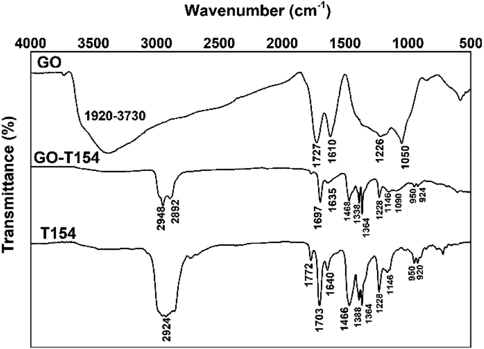
The FTIR spectrum exhibited the functional group variation from GO to GO-T154 (Fig. 1). As shown in Fig. 1, the characteristic peak of GO was C–O at 1050 cm−1, the C–OH at 1226 cm−1, the O–H at 1373 cm−1, and the C![[double bond, length as m-dash]](https://www.rsc.org/images/entities/char_e001.gif) O at 1727 cm−1.19,20 However, the characteristic absorbance peaks of GO-T154 were substantially different. The peak of the oxygen-containing groups on GO was mostly disappeared, indicating that GO was reduced during the modification process. This conclusion was further confirmed by the TGA and XPS results. Instead, most of the characteristic peaks of GO-T154 were highly similar to those of T154, e.g. the CC peaks of isobutene at 1388 cm−1 and 1364 cm−1, the CO peaks associated with acid amides at 1697 cm−1 and 1635 cm−1 and the N–H stretching at 2948 cm−1 and 2892 cm−1, etc. A new band for GO-T154 at 1090 cm−1, referred to a C–N stretching vibration, was not in the spectrum of GO or in that of T154. These results indicated that the graphene oxide was aminated by T154.
O at 1727 cm−1.19,20 However, the characteristic absorbance peaks of GO-T154 were substantially different. The peak of the oxygen-containing groups on GO was mostly disappeared, indicating that GO was reduced during the modification process. This conclusion was further confirmed by the TGA and XPS results. Instead, most of the characteristic peaks of GO-T154 were highly similar to those of T154, e.g. the CC peaks of isobutene at 1388 cm−1 and 1364 cm−1, the CO peaks associated with acid amides at 1697 cm−1 and 1635 cm−1 and the N–H stretching at 2948 cm−1 and 2892 cm−1, etc. A new band for GO-T154 at 1090 cm−1, referred to a C–N stretching vibration, was not in the spectrum of GO or in that of T154. These results indicated that the graphene oxide was aminated by T154.
 |
| | Fig. 1 The FTIR spectrum graphics of GO-T154, GO, and T154. | |
The reaction between GO and T154 was further investigated by XPS (Fig. 2), which also confirmed the reduction and covalent functionalization of GO with T154. The deconvolution of C 1s XPS peaks of GO showed three components that corresponded to carbon atoms in different functional groups, i.e., CO bonds (288 eV), C–O/C–N bonds (286 eV), and the ring C (284.5 eV).21,22 In the C 1s XPS spectrum of GO-T154, the peak intensities of the oxygen functionalities were greatly reduced compared to those in the GO spectrum, which further confirmed the deoxidation effect. The increased atomic ratio of C (Table 1) indicated the restoration of the graphitic structure of GO after modification. The increase in the C ring bonds at 284.5 eV agreed with the element analysis result. The peak of C–O at 286.9 eV was replaced by 285.5 eV in GO-T154, which indicated that C–N bonds appeared in the GO-T154 sample.
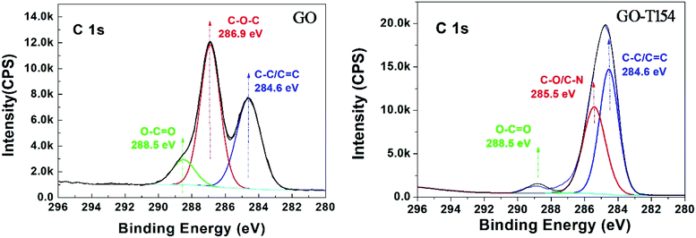 |
| | Fig. 2 The deconvolution of the peaks in C 1s XPS spectra of GO and GO-T154. | |
Table 1 The atomic ratio of the elements in GO and GO-T154 based on XPS analysis
| No. |
Name |
Atomic ratio (%) |
| C |
O |
N |
| 1 |
GO |
59 |
41 |
|
| 2 |
GO-T154 |
86 |
11 |
3 |
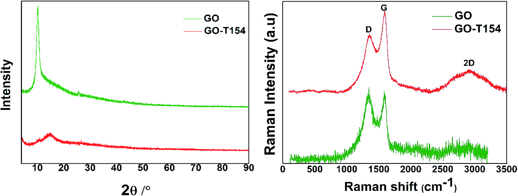
The XRD patterns reflected the crystal structures of GO and GO-T154, as shown in Fig. 3. The diffraction pattern of GO was typical, in which a peak at 2θ = 10.2° was corresponded to the (0 0 2) plane. The calculated value of d by Bragg's law is 8.67 Å, which was reported in former literature.23 As we know that the distance of graphite plates is 3.37 Å (2θ = 26.48°), and it is expanded to 8.67 Å (2θ = 10.2°) of GO by grafting with functional groups, such as hydroxyl, epoxy, and carboxyl during oxidation. However, the interlayer distance reduced to 5.89 Å (2θ = 15°) after reacting with T154, indicating most of the oxygen functional groups have been removed. The distance of GO-T154 sheets was not as tight as graphite due to the grafting of T154. Moreover, the broad peak of GO-T154 implied the disordered structure of randomly stacked GO-T154 sheets after filtration and drying. By sonication in a solvent, the stacked GO-T154 sheets could be separated into single-layer nanosheet, as shown in the micrograph in Fig. 4. The Raman spectra represented the ordered and disordered crystal structures of GO and GO-T154 was also shown in Fig. 3. For the Raman spectra of GO, the G band at approximately 1582 cm−1 originated from the in-plane vibration of the sp2 carbon atoms, and the D band reflect the defect of carbon structure was at about 1335 cm−1. As shown in Raman spectra of GO-T154, the integration area of the D band (1360 cm−1) was reduced and area of the G band (1590 cm−1) was increased compared to GO, which confirmed again the restoration of sp2 carbon structure during the reaction process.
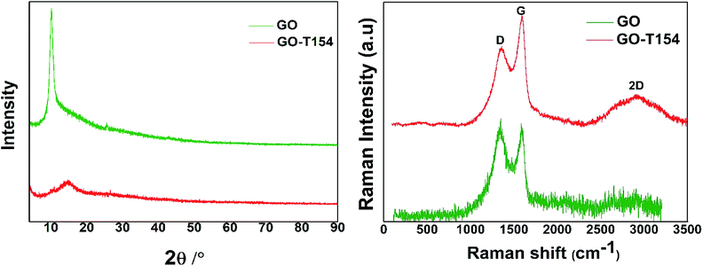 |
| | Fig. 3 XRD patterns (left) and Raman spectra (right) of GO and GO-T154. | |
 |
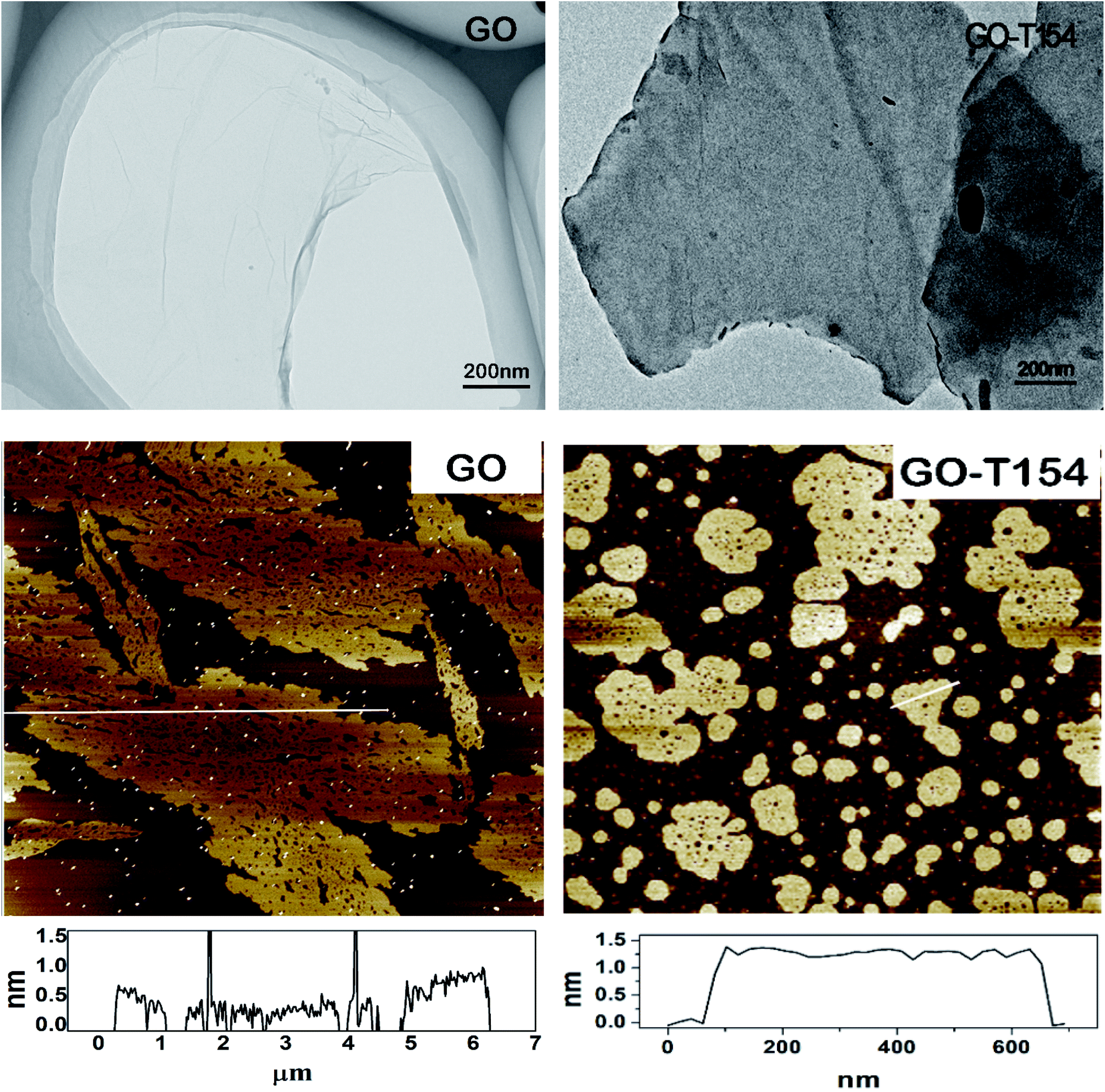
| | Fig. 4 The micrographs of GO and GO-T154. (The top row are the TEM micrographs, and the bottom row are the AFM images.) | |
The morphologies of nanoplatelets were observed by TEM and AFM in Fig. 4. In the TEM image, the GO was light in colour and almost transparent, implying the ultrathin nanolayer thickness. The sheet of GO was folded and wrinkled. After modification, the sheet of GO-T154 was in a deeper colour and smoother, which indicated it was thicker than GO nanosheet. The dimensions of GO-T154 were reduced to 0.8–3 μm compared to 10–30 μm of GO. During the functionalization, the reaction between GO and T154 was accompanied with a great number of groups removing from the graphene sheet, which could break the nanosheet and split the larger graphene into smaller pieces. Similar results were also reported by Liu J. et al.24 More specific mechanism of reaction process was according to Scheme 1. The dimension reduction could also be depicted from AFM image. Moreover, from the AFM image, the thickness of the GO-T154 sheets, as determined by quantitative testing, increased to 1.25 nm from 0.8 nm of GO. These results were close to the data of octadecylamine-functionalized graphene.24 The increased thickness of GO-T154 was attributed to the connection of the T154. As mentioned in the experimental section, the AFM sample was prepared from droplets of a GO-T154/petroleum ether suspension. As a result, the morphology in the AFM image illustrated that the GO-T154 sheet was smooth and well dispersed in the petroleum ether. Considering the similarities between the chemical structure of the base oil and petroleum ether, long-term stability of the GO-T154/oil suspension could be interpreted according to the principles of dissolution of similar material structures.
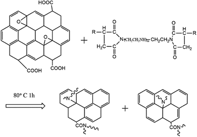 |
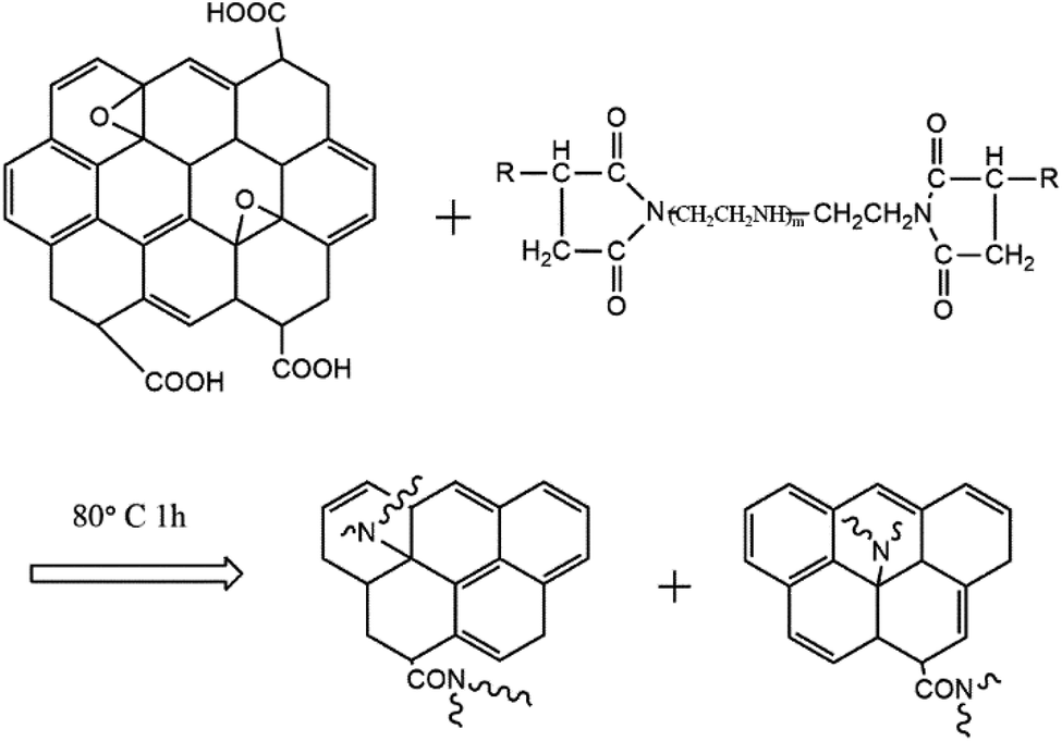
| | Scheme 1 Schematic diagram for the modification reaction between GO and T154. | |
Based on the characterization of GO and GO-T154, we could predict the probable reaction process between GO and T154. As shown in Scheme 1, the amide group of T154 could react with both the epoxide groups and carboxyl groups on the graphene sheet through nucleophilic addition, and then the long organic chains were grafted onto the graphene sheet. Since the reaction between the epoxide group and amine group was rapid and accompanied by the elimination of a large number of small molecules and rupture of amounts of chemical bond, the graphene sheets were “cut off” into small pieces.
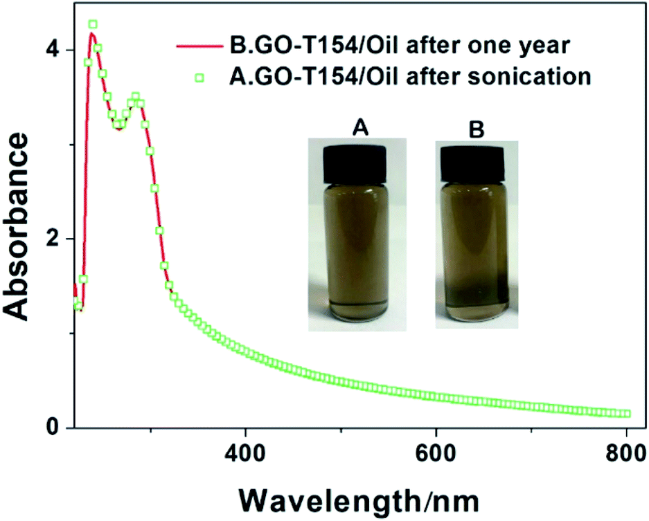
Natural precipitation of GO and modified GO suspension was observed by digital photograph and UV-Vis absorption spectra. The as-prepared GO-T154 was dispersed in PAO4 at a concentration of 0.5 mg mL−1 with the aid of bath ultrasonication, labelled as (1) in Fig. 5a, GOOS and GO(T154) suspensions ((2) and (3) in Fig. 5a) were also prepared as described above for comparison with GO-T154 (refer to the details in the experimental section). Fig. 5 shows digital pictures of the dispersions after sonication (a) and settle for one day (b and c). As seen in Fig. 5b, both the GO modified by oleic acid and stearic acid and the non-covalently functionalized GO showed short-term stabilities in oil, and their suspensions tended to precipitate and separate after just one day. On the bottom of the vials, black solid precipitates were observed for GOOS and GO, however, there were no deposits in the bottle of the GO-T154 dispersion. To observe the dispersions more clearly, magnified pictures under intense light are shown in Fig. 5d–f. The intense light facilitated the observation of the inside of the dispersion. As seen from the pictures, the suspension of GO-T154 was clear and transparent, while the suspensions of GOOS and GO(T154) were opaque. This phenomenon implied that the GO-T154 sheets were well dispersed in oil, and hardly any sheets had aggregated. As a result, the size of the particles remained small and compatible with the oil, so that the GO-T154 oil suspension was almost transparent. The dispersibility of GO-T154 in oil was also confirmed by UV-Vis absorption spectra (Fig. 6). We noticed that the GO-T154/oil suspension after one year had almost the same absorption intensity as that of the newly sonicated suspension. The digital photographs are the corresponding suspensions. All of these results illustrated that GO-T154 had extraordinary long-term stability in suspension, which could be explained by the suspension dynamics of the nanoparticles. According to suspension dynamics,25 the forces acting on the nanoparticle are balanced either in the vertical direction or in the horizontal direction. In the horizontal direction, the nanoparticles were mainly affected by van der Waals forces (F1, eqn (1)), electrostatic repulsion (F2, eqn (2)) and steric hindrance. In the vertical direction, the sinking force and viscous resistance remained equal, and the settling rate (v0) was deduced from eqn (3).
| | |
F2 = εΦ2dexp(1 − κH)/4
| (2) |
Λ is the Hamaker constant;
d is the particle dimension;
H is the distance between two particle centres;
ε is the dielectric constant of the solution;
Φ is the particle surface potential;
κ is the ionic atmosphere reciprocal;
ρ is the particle density;
ρ0 is the solution density;
g is the acceleration of gravity; and
η is the liquid viscosity.
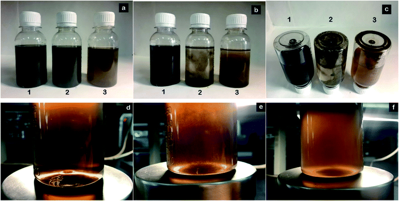 |
| | Fig. 5 Digital photographs of GO-T154, GOOS and GO(T154) in PAO4 oil before and after settling for one day: (a) photograph of the suspensions after sonication; (b) photograph of the suspensions after settling for 1 day; (c) the bottom of the bottles in photograph (b); (d) a magnified photograph of (1) in photograph (a); (e) a magnified photograph of (2) in photograph (a); and (f) a magnified photograph of (3) in photograph (a); (1) GO-T154; (2) GOOS; and (3) GO(T154). | |
 |
| | Fig. 6 UV-vis spectra of GO-T154/oil suspensions after sonication and settling for one year (the inset images are the digital photographs of the corresponding suspensions). | |
For GO-T154, the nanosheets were surround by T154 molecules, and compared to oleic acid and stearic acid, T154 has several advantages. First, T154 is an amide compound that can react with epoxy groups and carboxyl groups, while oleic acid and stearic acid can only react with carboxyl groups. Therefore, T154 had a higher grafting density. The grafted long chains increased the distance between two particle centres (H), and F1 decreased faster than F2. Therefore, the nanosheets tended to remain separated. Second, as a polymeric surfactant, T154 has a longer molecular chain than either oleic acid or stearic acid, which can prevent the graphene sheets from accumulating due to increased steric effects. After modification with T154, the dimensions of the graphene sheet had noticeably decreased. According to the settling rate equation (eqn (3)), v0 is greatly reduced with decreasing diameter. As a result, graphene sheets with greatly reduced dimension of GO-T154 was more stable in oil.
Thermogravimetric analysis was performed to evaluate the thermal stability of graphene in Fig. 7. This characteristic is significant since the frictional heat generated during the friction processes greatly affects the stability of oil additives. The first mass loss of GO was from 120 °C to 300 °C, which was attributed to the removal of oxygen–containing functional groups.26 After modification by T154, the thermal stability was greatly improved. From the TGA curve of GO-T154, there was nearly no weight loss before 300 °C. According to the above analysis, because of the reduction of graphene oxide by T154, the oxygen–containing functional groups were replaced by carbon skeleton, so the weight loss caused by the oxygen-containing groups before 300 °C was eliminated. The drastic weight loss at 320 °C was attributed to the decomposition of T154, which had the same trend as the thermostability results of T154 (the small inset graph in Fig. 7). However, the decomposition temperature range was improved greatly, from 190–400 °C to 320–550 °C. It seemed that graphene sheet played a protecting role to molecular chains of T154. The thermostabilities of oleic acid and stearic acid were also studied for comparison with that of T154. As shown in the inset of Fig. 8, oleic acid and stearic acid decomposed at 220 °C, indicating that GO grafted by these micromolecular modifiers was not as stable as GO-T154 under frictional heat. Moreover, the residue of GO-T154 after thermal decomposition was less than GO. This was due to part of the weight of GO was replaced by T154, and there was almost no residue of T154. Since the carbon residue will accumulate and blocks the oil system, so we pleased to avoid the residue of lube oil. This might be another advantage of GO-T154 as oil additive.
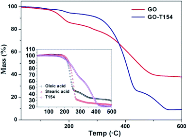 |
| | Fig. 7 TGA of GO and GO-T154. The small inset graph shows the TGA results of oleic acid, stearic acid and T154. | |
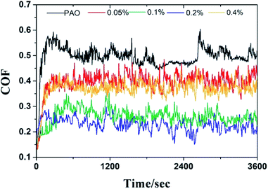 |
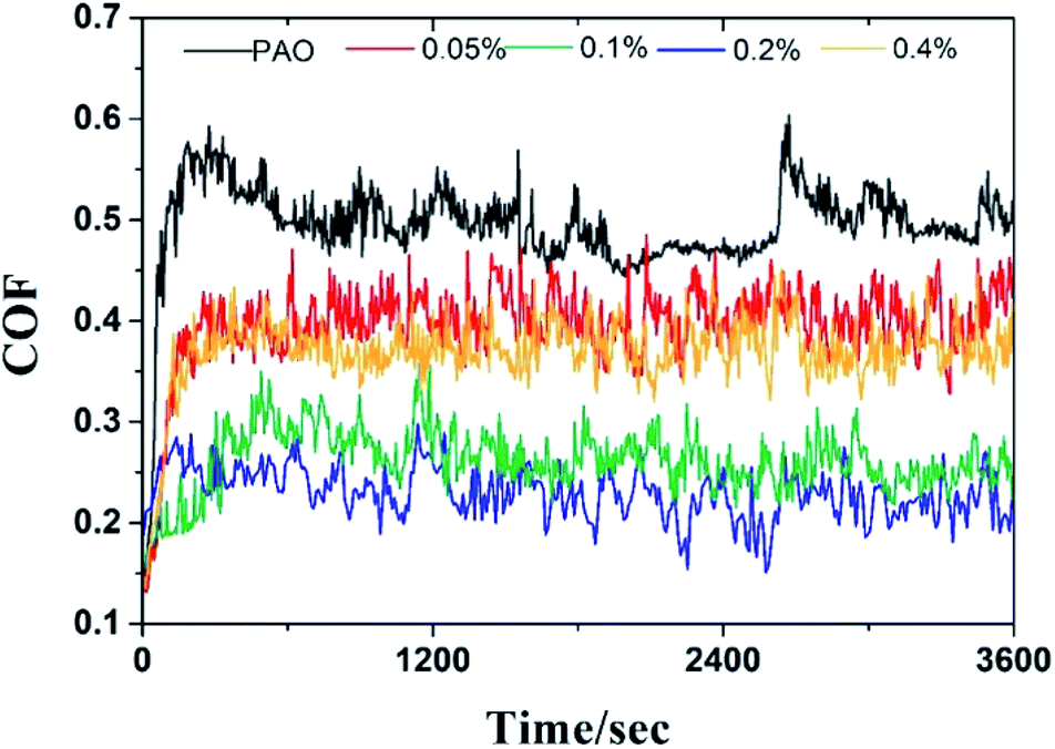
| | Fig. 8 The friction coefficient curves of the GO-T154/oil samples with different concentrations. | |
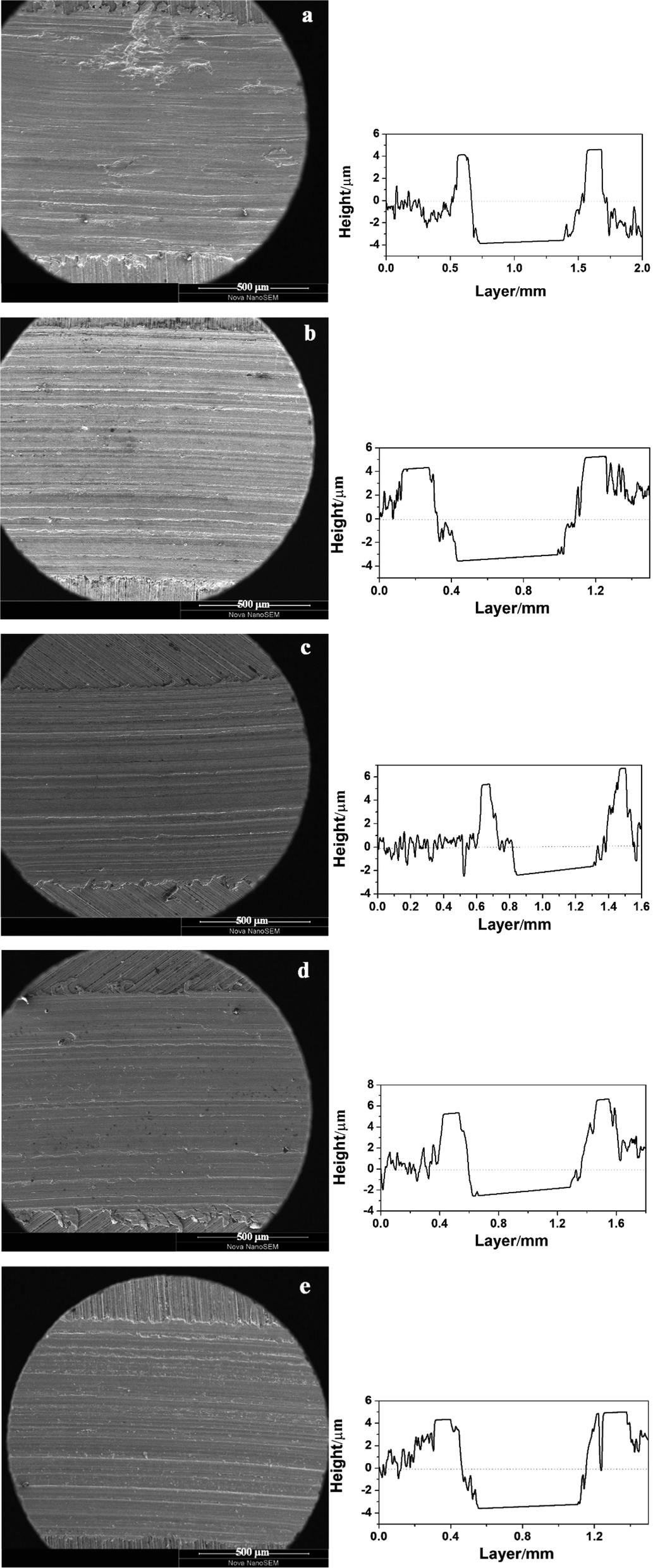
The tribological performance was examined by a UMT-3 tribo-tester and step profiler. Fig. 8 showed the friction coefficient curves (COF as a function of sliding time) of oil with different concentration of GO-T154, and the average friction coefficient (AFC) was recorded in Table 2. For the base oil, the friction coefficient fluctuated greatly during friction process, and the AFC was the highest (0.49). The introduction of GO-T154 decreased the friction coefficient obviously. When 0.05 wt% GO-T154 was dispersed into PAO4, the AFC was reduced to 0.39, indicating that GO-T154 could act as lubricant in base oil. The AFC was further decreased as the concentration of GO-T154 was increasing. To be specific, the AFC of PAO containing 0.1 wt% GO-T154 was 0.26 and that of PAO with 0.2 wt% GO-T154 was 0.22. However, when the concentration increased to 0.4 wt%, the AFC turned to increase. The variation of AFC with concentration of GO-T154 could be interpreted through wear track analysis by SEM and step profiler (Fig. 9 and 10). As for the worn track of specimen with base oil in Fig. 9a and 10a1, the characteristic morphology was the chipping pit and micro metal debris. That might be due to the fracture of oil film under experiment load, two metal surfaces contacted frequently, so that the debris was peeled off from the softer one. Thus, the accumulated debris and rough surface resulted in high friction coefficient. When the GO-T154 was dispersed into base oil, the chipping pit was almost disappeared and the typical morphology turned to furrow caused by plastic deformation in Fig. 9b–e. The amplified back scattering image (Fig. 10b2–e2) showed the carbon film was formed on the counterpart surface (the blacker layer compared to matrix). As the increasing of GO-T154, the carbon film was more complete and the worn surface was smoother. When the concentration of GO-T154 was 0.2 wt%, the trace of graphene sheet could be observed (Fig. 10d1). This indicated that graphene sheets could slip into rubbing gap, which shared part of shear stress through nanosheets delamination. Thus, the AFC was decreased greatly. However, as the concentration of GO-T154 was up to 0.4 wt%, plenty of scratches were shown on worn surface of Fig. 10e1. The carbon film was not as obvious as that of 0.2 wt%, which might due to the restacking of graphene sheets in high concentration oil suspension blocked rubbing gap and prevented the GO-T154 sheets and oil film from slipping into the rubbing gap.
Table 2 The AFC and wear rates (mean (n = 3) ± SD) of the GO-T154/oil samples with different concentrations
| No. |
GO-T154 (wt%) |
AFC |
Wear volume (mm3) |
Wear rate (mm3 N−1 m−1) |
| 1 |
0 |
0.48 ± 0.028 |
0.291 ± 0.004 |
(1.62 ± 0.02) × 10−4 |
| 2 |
0.05 |
0.39 ± 0.012 |
0.219 ± 0.009 |
(1.22 ± 0.05) × 10−4 |
| 3 |
0.1 |
0.26 ± 0.011 |
0.170 ± 0.004 |
(9.45 ± 0.2) × 10−5 |
| 4 |
0.2 |
0.22 ± 0.014 |
0.116 ± 0.005 |
(6.43 ± 0.3) × 10−5 |
| 5 |
0.4 |
0.36 ± 0.013 |
0.200 ± 0.009 |
(1.11 ± 0.05) × 10−4 |
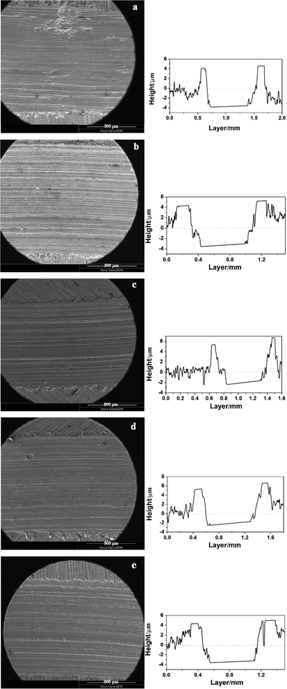 |
| | Fig. 9 The SEM images of various wear tracks on the discs and the height profile measurements of the corresponding tracks: (a) 0% GO-T154; (b) 0.05 wt% GO-T154; (c) 0.1 wt% GO-T154; (d) 0.2 wt% GO-T154; and (e) 0.4 wt% GO-T154. | |
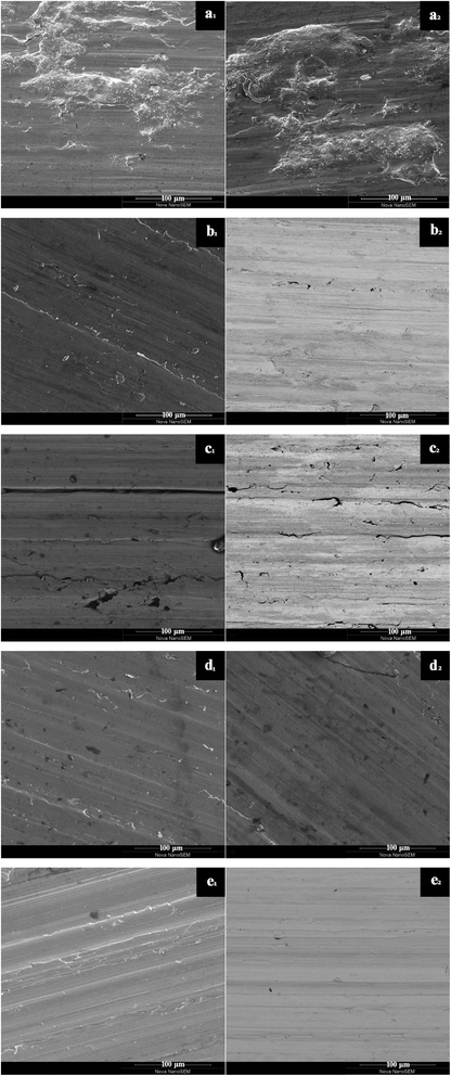 |
| | Fig. 10 The secondary electron image (left) and backscatter electron image (right) of the wear tracks: (a) 0% GO-T154; (b) 0.05 wt% GO-T154; (c) 0.1 wt% GO-T154; (d) 0.2 wt% GO-T154; and (e) 0.4 wt% GO-T154. | |
The antiwear properties reflected by height profile was shown in Fig. 9, and the calculated wear rate results were also listed in Table 2. The wear volumes (ΔV, mm3) of the samples were approximately calculated according to the following equation:
where Δ
V is the wear volume (mm
3),
S is the contour area (mm
2),
l is the length of the wear track (mm). The wear rates (
K, mm
3 N
−1 m
−1) of the samples were calculated from the following equation:
where
F is the applied load (N), and
t is the experimental duration (s).
As a whole, the GO-T154 also acted as antiwear agents in oil for all concentration. For the optimal performance, the wear rate decreased by 60% compared to base oil as the concentration of GO-T154 was 0.2%. From observation by SEM in Fig. 9 and 10, the rubbing trace of the 0.2 wt% GO-T154 sample was shallow and smooth, covered with a continuous and uniform carbon film, which could separate the relevant moving components so that decrease the wear rate. When the concentration of GO-T154 was lower than 0.2 wt%, the carbon film was not continuous, and the contact surface was rougher. On the other hand, when the concentration of GO-T154 was 0.4 wt%, the rubbed surface turned to be rough again. These results indicated that the quality of carbon film rely on the concentration and dispersed state of GO-T154.
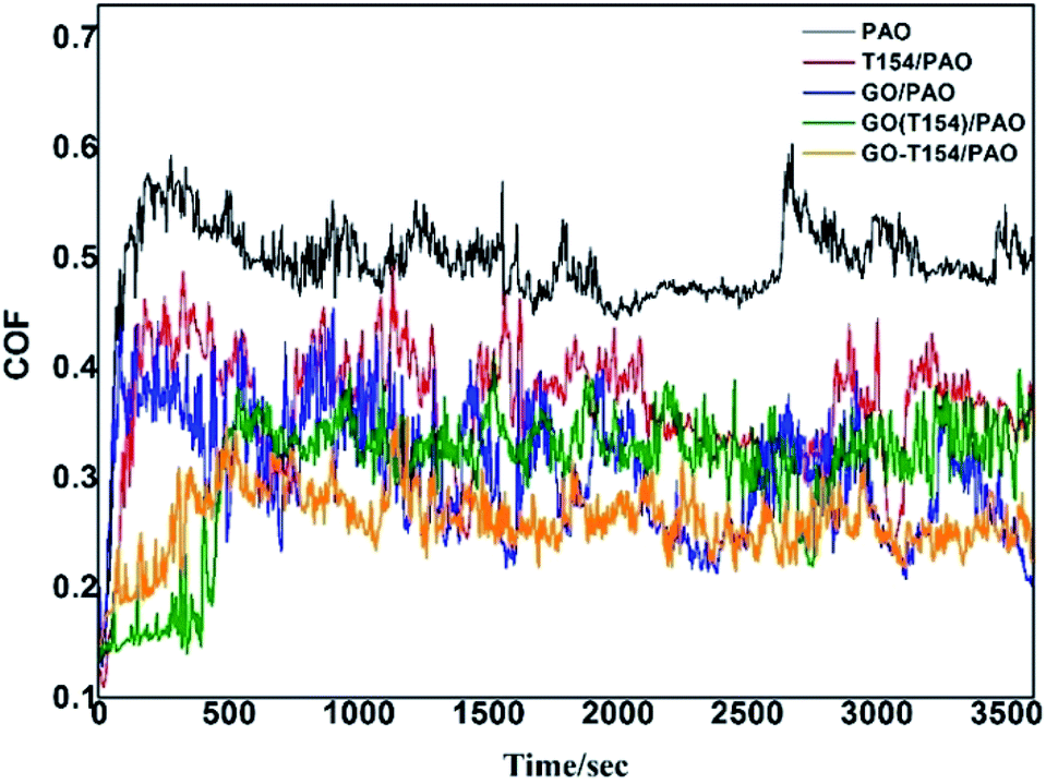
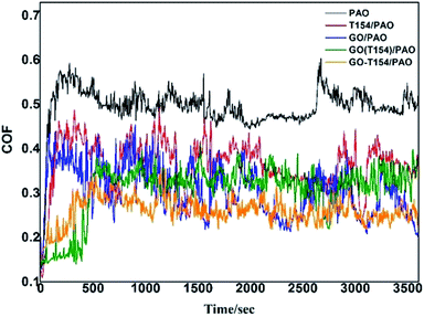
In order to understand the lubricating and antiwear mechanism of GO-T154 in oil, tribological properties of PAO with different additives were further tested. Fig. 11 exhibited the friction coefficients of the base oil dispersed with different fillers, and all the oil suspensions were at the same concentration of 0.2 wt%.
 |
| | Fig. 11 The friction coefficient curves of PAO with different additives. | |
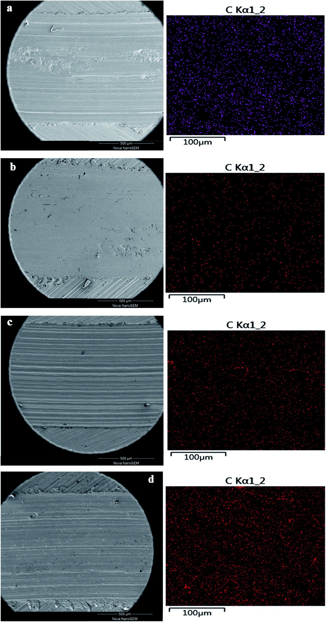
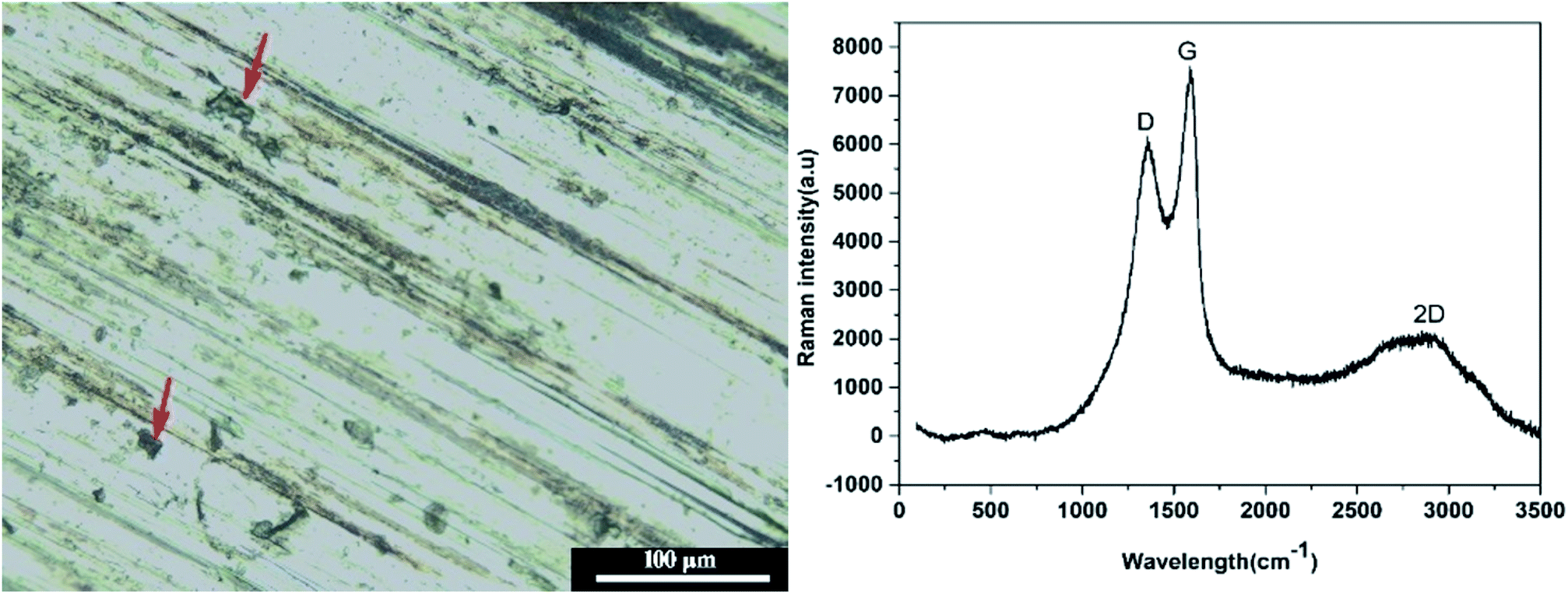
The summarized average COF and calculated wear rate for all samples were listed in Table 3. As can be seen, both T154 and GO could reduce the AFC and wear rate of base oil, but not as effective as GO-T154. PAO containing the mixture of GO and T154 displayed better lubricating and antiwear properties than either T154 or GO alone. Even better, PAO with GO-T154 showed the lowest AFC of 0.22, decreased by 54% from base oil, and the minimum wear rate, which reduced by 60% compared to pure oil. To understanding the wear mechanism, the wear tracks were further investigated by SEM, EDS and Raman spectrum analysis. As for oil with T154, the stickiness of T154 make it easy to form transfer film on friction surface, which could directly confirm by carbon mapping using EDS (Fig. 12). However, this transfer film was not continuous with such a low concentration of T154 and lack of solid lubricant, so its friction coefficient was high and unstable. With a nanosheet structure, GO could decrease shear stress through delamination effect, reduce the roughness by filling the surface defect and form carbon film. However, the dispersity of GO in oil was not stable, which tend to restack so that few nanosheet could slip into friction gap. Hence, the transfer film was not continuous either, which was also discovered by carbon mapping result. When GO was modified by T154 with noncovalent interaction, GO cannot stably disperse in base oil either (According to the suspension experiment). The tribological properties of GO(T154)/oil exhibited a same trend as GO/oil suspension, for which GO deposit on metallic substrate mostly, and could not supply to the friction surface. As a result, the AFC and wear rate were close to those of GO/oil suspension, and the friction coefficient was not steady either. Attributed to the grafting of T154 onto GO nanosheet, the superior performance of GO-T154 may result from the synergistic effect of GO nanosheet and T154. Decorated by T154, the stickiness of nanosheet was enhanced, which made it easier to form uniform and continuous transform film on friction surface, evidencing from the carbon mapping in Fig. 12c. Moreover, the Raman spectra of wear track of specimen with GO-T154/oil (Fig. 13) showed G peak and D peak of GO-T154 on the transfer film, which illustrated the existence of GO-T154 nanosheet on friction surface. The nanosheet of GO-T154 could absorb part of shear stress, thereby the AFC was reduced and antiwear property was enhanced. Therefore, the AFC and wear rate of GO-T154/oil were the lowest, and the friction coefficient was steady.
Table 3 The AFC and wear rates of the base oil with different additives
| No. |
Filler |
AFC |
Wear volume (mm3) |
Wear rate (mm3 N−1 m−1) |
| 1 |
None |
0.49 ± 0.028 |
0.291 ± 0.004 |
(1.62 ± 0.02) × 10−4 |
| 2 |
T154 |
0.30 ± 0.012 |
0.242 ± 0.009 |
(1.34 ± 0.05) × 10−4 |
| 3 |
GO |
0.29 ± 0.021 |
0.181 ± 0.005 |
(1.0 ± 0.03) × 10−4 |
| 4 |
GO(T154) |
0.28 ± 0.015 |
0.176 ± 0.004 |
(9.78 ± 0.2) × 10−5 |
| 5 |
GO-T154 |
0.22 ± 0.014 |
0.116 ± 0.005 |
(6.43 ± 0.3) × 10−5 |
 |
| | Fig. 12 The wear track of different samples and corresponding carbon mapping ((a) T154/PAO; (b) GO/PAO; (c) GO(T154)/PAO; (d) GO-T154/PAO). | |
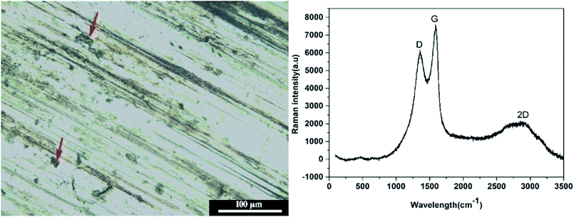 |
| | Fig. 13 The optical micrograph of wear trace of GO-T154/PAO (left) and Raman spectra of corresponding position (right). | |
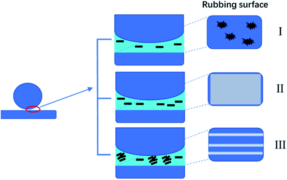
Based on the above study, GO-T154 as effective lubricant to reduce the COF and wear rate through three approaches: (1) the nanosized solid lubricant filled the gap and defect on sliding surface, thus reduced the surface roughness; (2) the well dispersed GO-T154 slipped into the friction gap and shared part of shearing stress; (3) after long-term sliding, a continuous transfer film formed which separated the friction surfaces. The tribological performance of the ball-on-disk friction test could be explained by film transfer theory,27,28 as depicted in Scheme 2. When the concentration of GO-T154 was low, the content of the nanofiller was not sufficient to form a continuous carbon film to completely cover the rubbed surface (I). At the optimal concentration, a uniform and continuous carbon film was formed, separating the relevant moving surfaces and sharing part of shear stress by nanosheet delamination, thus the friction and wear were greatly decreased (II). However, when the content of nanosheet was higher than optimal value, the nanosheets tended to restack. The stacking graphene might block the rubbing gap, preventing the nanosheet and oil film from sliding into friction surface. Some of the aggregates even acted as abrasive particles, scratching the rubbed surface (III).
 |
| | Scheme 2 Schematic diagram of the tribological mechanisms of GO-T154/oil samples with different concentrations. | |
4. Conclusion
In summary, GO was successfully modified with T154 through a simple reflux reaction. For the prepared GO-T154, the macromolecular of T154 covered the surface of the graphene sheet and the dimensions of the graphene sheets were greatly decreased. These variations were beneficial for dispersion stability of the modified graphene sheets in oil, so that the GO-T154/oil suspension showed long-term suspension stability for more than one year. Moreover, GO-T154 exhibited an exceptional heat stability performance. The tribological test further showed improved lubricating properties and anti-wear properties of oil dispersed with GO-T154. For the optimal performance of GO-T154/oil, the friction coefficient decreased by 54%, and the wear rate decreased by 60% compared to those of base oil. According to the wear track analysis, it was attribute to the synergistic effect of T154 macromolecular and graphene nanosheets, a uniform and continuous carbon film formed on contacting surface, which resulted in the superior performance of GO-T154/oil suspension. This modification of GO was successful and the related study was extremely valuable, which promoted graphene to be closer to industry applications as an additive in oil.
Conflicts of interest
There are no conflicts to declare.
References
- A. K. Rasheed, M. Khalid, W. Rashmi, T. C. S. M. Gupta and A. Chan, Graphene based nanofluids and nanolubricants – Review of recent developments, Renewable Sustainable Energy Rev., 2016, 63, 346–362 CrossRef CAS.
- D. Berman, A. Erdemir and A. V. Sumant, Few layer graphene to reduce wear and friction on sliding steel surfaces, Carbon, 2013, 54, 454–459 CrossRef CAS.
- S. Adolfo, D. Vincenzo, P. Vincenzo, C. Paolo and S. Maria, Graphene Oxide Nanosheets as Effective Friction Modifier for Oil Lubricant: Materials, Methods, and Tribological Results, ISRN Tribol., 2013, 425809 Search PubMed.
- O. Penkov, H. J. Kim, H.-J. Kim and D. E. Kim, Tribology of graphene: A review, International Journal of Precision Engineering and Manufacturing, 2014, 15(3), 577–585 CrossRef.
- D. Zheng, Y. Wu and Z. Li, et al., Tribological properties of WS2/graphene nanocomposites as lubricating oil additives, RSC Adv., 2017, 7(23), 14060–14068 RSC.
- J. Zhao, J. Mao, Y. Li, Y. He and J. Luo, Friction-induced nano-structural evolution of graphene as a lubrication additive, Appl. Surf. Sci., 2017, 434, 21–27 CrossRef.
- J. Lin, L. Wang and G. Chen, Modification of Graphene Platelets and their Tribological Properties as a Lubricant Additive, Tribol. Lett., 2011, 41(1), 209–215 CrossRef CAS.
- V. Eswaraiah, V. Sankaranarayanan and S. Ramaprabhu, Graphene-based engine oil nanofluids for tribological applications, ACS Appl. Mater. Interfaces, 2011, 3(11), 4221–4227 CrossRef CAS.
- W. Zhang, M. Zhou, H. W. Zhu, Y. Tian, K. L. Wang and J. Q. Wei, et al., Tribological properties of oleic acid-modified graphene as lubricant oil additives, J. Phys. D: Appl. Phys., 2011, 44(20), 205303 CrossRef.
- T. Chen, Y. Xia, Z. Jia, Z. Liu and H. Zhang, Synthesis, Characterization, and Tribological Behavior of Oleic Acid Capped Graphene Oxide, J. Nanomater., 2014, 2014, 1–8 Search PubMed.
- G. Bai, J. Wang and Z. Yang, et al., Preparation of a highly effective lubricating oil additive – ceria/graphene composite, RSC Adv., 2014, 4(87), 47096–47105 RSC.
- N. A. Ismail and S. Bagheri, Highly oil-dispersed functionalized reduced graphene oxide nanosheets as lube oil friction modifier, Mater. Sci. Eng., B, 2017, 222, 34–42 CrossRef CAS.
- H. P. Mungse and O. P. Khatri, Chemically Functionalized Reduced Graphene Oxide as a Novel Material for Reduction of Friction and Wear, J. Phys. Chem. C, 2014, 118(26), 14394–14402 CrossRef CAS.
- X. Wu, K. Gong and G. Zhao, et al., Mechanical synthesis of chemically bonded phosphorus–graphene hybrid as high-temperature lubricating oil additive, RSC Adv., 2018, 8(9), 4595–4603 RSC.
- S. José, M. D. Avilés, N. Saurín, T. Espinosa, F. J. Carrión and M. D. Bermúdez, Synergy between graphene and ionic liquid lubricant additives, Tribol. Int., 2017, 116, 371–382 CrossRef.
- M. Yuan, F. Su and Y. Chen, Supercritical Fluid Synthesis and Tribological Applications of Silver Nanoparticle-decorated Graphene in Engine Oil Nanofluid, Sci. Rep., 2016, 6, 31246 CrossRef.
- H. Wenxuan. Guide for application of lubricant additives. China Petrochemical Press. China. 2003 Search PubMed.
- W. S. Hummers and R. E. Offeman, Preparation of graphitic oxide, J. Am. Chem. Soc., 1958, 6, 1339 CrossRef.
- Y. Xu, H. Bai, G. W. Lu, C. Li and G. Q. Shi, Flexible graphene films via the filtration of water-soluble noncovalent functionalized graphene sheets, J. Am. Chem. Soc., 2008, 130, 5856–5857 CrossRef CAS.
- S. Lee, S. Lim and E. Lim, Synthesis of aqueous dispersion of graphenes via reduction of graphite oxide in the solution of conductive polymer, J. Phys. Chem. Solids, 2010, 71, 483–486 CrossRef CAS.
- S. Biniak, G. Szymański, J. Siedlewski and A. Swiatkowski, The characterization of activated carbons with oxygen and nitrogen surface groups, Carbon, 1997, 35, 1799–1810 CrossRef CAS.
- J. Gao, F. Liu, Y. L. Liu, N. Ma, Z. Q. Wang and X. Zhang, Environment–friendly method to produce graphene that employs vitamin C and amino acid, Chem. Mater., 2010, 22, 2213–2218 CrossRef CAS.
- M. Hirata, T. Gotou, S. Horiuchi, M. Fujiwara and M. Ohba, Thin-film particles of graphite oxide 1: high–yield synthesis and flexibility of the particles, Carbon, 2004, 42, 2929–2937 CAS.
- J. Liu, Y. Wang, S. Xu and D. D. Sun, Synthesis of graphene soluble in organic solvents by simultaneous ether-functionalization with octadecane groups and reduction, Mater. Lett., 2010, 64(20), 2236–2239 CrossRef CAS.
- J. H. Hu, Z. X. Yang and Z. Zheng, Colloid and Interface Chemistry, South China University of Technology Press, Guangzhou, 1997, pp. 255–97 Search PubMed.
- J. Shen, Y. Hu, M. Shi, X. Lu, C. Qin, C. Li and M. X. Ye, Fast and Facile Preparation of Graphene Oxide and Reduced Graphene Oxide Nanoplatelets, Chem. Mater., 2009, 21, 3514–3520 CrossRef CAS.
- L. Wu, L. Gu, Z. Xie, C. Zhang and B. Song, Improved tribological properties of Si3N4/GCr15 sliding pairs with few layer graphene as oil additives, Ceram. Int., 2017, 43(16), 14218 CrossRef CAS.
- J. Mao, J. Zhao, W. Wang, Y. Y. He and J. B. Luo, Influence of the micromorphology of reduced graphene oxide sheets on lubrication properties as a lubrication additive, Tribol. Int., 2018, 119, 614–621 CrossRef CAS.
|
| This journal is © The Royal Society of Chemistry 2019 |
Click here to see how this site uses Cookies. View our privacy policy here. 
 Open Access Article
 This Open Access Article is licensed under a Creative Commons Attribution-Non Commercial 3.0 Unported Licence
 ab,
Zhiyong Wang*b,
Yan Zhao
ab,
Zhiyong Wang*b,
Yan Zhao