DOI:
10.1039/C9RA07505D
(Paper)
RSC Adv., 2019,
9, 39561-39571
Facile route for C–N/Nb2O5 nanonet synthesis based on 2-methylimidazole for visible-light driven photocatalytic degradation of Rhodamine B†
Received
17th September 2019
, Accepted 26th November 2019
First published on 2nd December 2019
Abstract
Herein, we fabricated a C and N co-modified Nb2O5 nanonet structure (C–N/Nb2O5NNs) from niobium oxalate using 2-methylimidazole (Hmim) as a source for C and N via a simple hydrothermal route. The obtained nanonets are robust and cost-effective with excellent recycling stability. Compared with N-doped TiO2 (N-TiO2) and a Nb2O5 control sample (Nb2O5-CS), the resulting nanonets exhibited the highest performance toward the photocatalytic degradation of Rhodamine B (RhB) upon visible light irradiation (λ > 420 nm). Through this study, we revealed that the synergetic effects of C and N on the nanonet surface, which were effectively incorporated into the surface of the Nb2O5 nanonet structure, not only remarkably enhanced the visible light response by decreasing the bandgap to 2.9 eV but also improved the light utilization efficiency and photo-induced electron–hole pair separation efficiency of our nanonet structure. We also proposed that the presence of carbonate species (COx) and nitrogen species (NOx) increased the population of generated holes (h+) that had the key role in the photodegradation mechanism of RhB, suggesting reasonable importance for the modification of Nb2O5 with C and N. This synergism offers a new view to reveal the origin of photodegradation processes, introducing h+ as a key intermediate. Our approach provides a new insight to design 2D nanostructures with potential applications in catalysis, solar energy conversion, and environmental protection.
1. Introduction
Solar energy utilization is one of the most rapidly developing fields in the past several decades. In this regard, semiconductor nanostructures have been revealed as one of the main materials that participate efficiently in converting solar energy to electrical or chemical energy.1 Despite the progress on the synthesis of two-dimensional (2D) nanomaterials, the design of low-cost, well-ordered, nanonet catalysts for photocatalytic applications with efficient catalytic activity remains one of the great challenges in this field. Moreover, fabricating a novel, low-cost nanophotocatalyst with a bandgap in the visible light region is another potential challenge. On the other hand, the existence of organic pollutants such as pharmaceuticals, pesticides, and dyes in rivers and lakes, even at low concentrations, can seriously affect human health and the environment. Rhodamine B (RhB) which is the most used dye in the textile industry, is classified as an organic pollutant and is more likely to be found in wastewater, threatening the human health and environment due to its potential carcinogenicity and its resistance to biodegradation.2–4 Accordingly, developing an efficient treatment technology for the removal of such pollutants from wastewater is urgent.
For instance, the heterogeneous photocatalysis have attracted a great interest for the photocatalytic degradation, particularly the use of semiconductors that can be active under visible irradiation due to their excellent characteristics such as low toxicity, high photocatalytic activity, and relatively high stability.5,6 Moreover, modification of the semiconductor surfaces either by introducing some molecules to the surface or changing the surface molecules critically enhances the electrons transfer from the valence band (VB) to the conduction band (CB) through shortening the bandgap of the targeted semiconductor.7 Notably, many efforts have been paid to optimize the structure and morphology of the semiconductor photocatalysts to upgrade their visible–visible light absorption and charge separation efficiency.8
As an n-type semiconductor based transition metal, Nb2O5 has been widely studied in sensors, electrochromic, and bioelectrochemistry.9–11 Accordingly, Nb2O5 has been found to be a promising material for photocatalytic reactions.12–14 Nevertheless, the actual application of Nb2O5 as a photocatalyst is limited due to its wide band gap (3.4 eV) which lies in UV region. Therefore, developing a novel visible light-responded Nb2O5 photocatalyst with suitable electron–hole pair lifetimes via simple synthesis methods is necessary for wide use applications and sunlight utilization. Interestingly, the modification of Nb2O5 with non-metal elements is one of the most effective methods to shift its spectrum to the visible light region.15 Based on the fact that doping the nanostructured semiconductor catalysts with non-metal elements can effectively harvest visible light due to N doping that narrows the bandgap by mixing the N 2p and O 2p, inducing visible light absorption.16 In this regard, Sato reported the photocatalytic activity of N-doped TiO2.17 In that work, doping the photocatalyst with nitrogen led to a visible-light response and contributed to the formation of NOx. In addition, Wang et al. prepared N-doped Nb2O5 sensitized by carbon nitride polymer which showed a relatively higher visible light photocatalytic activity.18 On the other hand, we assume that using carbon as a support can develop different interactions with the photocatalyst that lead to enhancing the electron transfer since its significant rule has been widely established in catalytic-based materials.19,20 Furthermore, Ge et al. modified Nb2O5 nanostructured catalysts with carbon that showed a powerful absorption in the visible light area ascribed to the presence of COx that acts as a sensitizer on the catalysts surface, improving the photocatalytic activity of the as-prepared catalysts toward the degradation of RhB and photoinduced hydrogen creation.21 In this regards we suppose that the two-dimensional (2D) structure of the Nb2O5 nanonets can facilitate the diffusion of reactant molecules and allow them to access the effective surfaces more easily, shorten the transit time of charge carriers, and reduce the rate of e−–h+ recombination which is beneficial to the enhancement of the photocatalytic activity.22,23 To date, the synthesis of 2D C and N co-modified Nb2O5 nanonets has not been reported.
Therefore, in this work C–N/Nb2O5NNs photocatalysts were prepared via a simple hydrothermal synthesis method in the presence of 2-methylimidazole (Hmim) to obtain nanonetstructures, followed by calcination to modify the nanonets with C and N species. It is noteworthy that Hmim can interact with nanomaterials through physical adsorption meanwhile the lone pair electron on the nitrogen can form a coordination bond with niobium to be used as C and N source for C and N co-modification. C and N were effectively modified into the surface of Nb2O5 nanonets without disturbing the nanonet structure, which significantly improved the visible light photocatalytic activity. The photocatalyst structure and its relationship with the photocatalytic activity and reaction mechanism were also discussed intensively, revealing the synergetic effects of C and N co-modification.
2. Experimental section
2.1. Materials
All chemicals were of analytical grade and used without any further purification. Niobium oxalate was purchased from Shanghai D&B Biological Science and Technology Co., Ltd. (Shanghai, China). Hmim was purchased from Shanghai Yuanye Biotechnology Co., Ltd. (Shanghai, China). Rhodamine B, ammonium oxalate, benzoquinone, and tertiary butanol were bought from Shanghai Aladdin Bio-Chem Technology Co., Ltd. (Shanghai, China).
2.2. Preparation of C–N/Nb2O5NNs
The Nb2O5 nanonets were synthesized by using a hydrothermal method as described previously with some modifications.24 In a typical synthesis, a 2 mmol niobium oxalate was dissolved in 25 mL of a co-solvent containing 15 mL deionized water and 10 mL absolute ethanol at 60 °C under stirring for 10 min to form solution A. To prepare solution B, a 1 mmol Hmim was dissolved in 5 mL deionized water with continuously stirring for 5 min. Thereafter, solution B was dropwisely added into solution A with vigorous stirring for 10 min at room temperature. The resultant mixture was taken to 50 mL Teflon-lined stainless-steel autoclave and heated at 180 °C for 24 h. After the autoclave was allowed to be cooled down to room temperature naturally, the white precipitate was repeatedly collected by centrifugation and re-dispersed in deionized water prior to be washed, and then dried in vacuum at 60 °C for overnight. C–N/Nb2O5NNs were synthesized by calcining the dried powder at 350 °C for 2 h. The calcination process resulted in the decomposition of Hmim to C and N while removing the other organic residuals. In order to get the best photocatalysts, we aimed to optimize the Nb2O5 nanonets synthesis. Accordingly, we have investigated some experimental parameters such as the concentrations of Hmim (from 15 mmol L−1 to 150 mmol L−1), the volumetric ratios of water to ethanol co-solvent (5![[thin space (1/6-em)]](https://www.rsc.org/images/entities/char_2009.gif) :1, 2:1, 1:1, and 1:2), the reaction time (1 h, 3 h, 6 h, 9 h, and 12 h), and the reaction temperature (140 °C, 160 °C, 180 °C, and 200 °C) to investigate the changes in the structural morphology at different reaction conditions. Finally, the calcination temperature parameter was investigated at 150, 250, 350 and 450 °C for 2 h to obtain a better C and N modified nanonets catalysts. The calcined products at different temperatures were denoted as C–N/Nb2O5NNs-x, where x stands for calcination temperature. In comparison, a Nb2O5 control sample (Nb2O5-CS) was prepared in the absence of Hmim while other optimized conditions were kept the same. Besides, N-doped TiO2 (N-TiO2) was prepared as a further control sample by calcining a finely ground mixture of TiO2 (0.1 g) and urea (0.3 g) at 400 °C for 3 h.
:1, 2:1, 1:1, and 1:2), the reaction time (1 h, 3 h, 6 h, 9 h, and 12 h), and the reaction temperature (140 °C, 160 °C, 180 °C, and 200 °C) to investigate the changes in the structural morphology at different reaction conditions. Finally, the calcination temperature parameter was investigated at 150, 250, 350 and 450 °C for 2 h to obtain a better C and N modified nanonets catalysts. The calcined products at different temperatures were denoted as C–N/Nb2O5NNs-x, where x stands for calcination temperature. In comparison, a Nb2O5 control sample (Nb2O5-CS) was prepared in the absence of Hmim while other optimized conditions were kept the same. Besides, N-doped TiO2 (N-TiO2) was prepared as a further control sample by calcining a finely ground mixture of TiO2 (0.1 g) and urea (0.3 g) at 400 °C for 3 h.
2.3. Characterization
The X-ray diffraction (XRD) patterns were recorded in the scope of 10 to 70° (2θ) on a Rigaku Ultima IV diffractometer utilizing Cu-Kα radiation. SEM images were acquired utilizing a Hitachi S-4800 electron microscope. TEM and HRTEM images of the samples were obtained on a JEOL JSM-3010 microscope. N2 adsorption–desorption isotherms were examined on a Quantachrome Quadrasorb SI apparatus at 77 K. UV-vis diffuse reflectance spectra of the samples were recorded by a Shimadzu UV-2550 spectrophotometer in the wavelength range of 200–800 nm and BaSO4 was used as a reference. Fourier transform infrared spectra (FT-IR) were recorded on a Nicolet-380 FT-IR from 400 to 4000 cm−1. X-Ray photoelectron spectroscopy (XPS) was performed on a Kratos Axis Ultra DLD spectrometer with a monochromatic Al-Kα X-ray source (hν = 1486.6 eV).
2.4. Photocatalytic activity testing
To investigate the catalyst photocatalytic activities, the degradation of Rhodamine B (RhB) under visible light irradiation was carried out using a photocatalytic reactor as can be seen in Scheme 1. In a typical procedure, a 0.1 g photocatalyst was dispersed in 100 mL aqueous solution of 10 mg L−1 RhB in a quartz reactor with a water-cooling jacket. In complete darkness, this slurry was stirred for 40 min to assure an adsorption–desorption equilibrium between the RhB molecules and photocatalyst prior to irradiation. Then, Xe lamp with a UV cut-off filter (420–700 nm) was turned on to illuminate the slurry under magnetic stirring. During the irradiation process, about 3 mL of the working solution was sampled at 5 min intervals and immediately centrifuged at 14000 rpm for 5 min to remove the photocatalyst particles. The concentrations of RhB were monitored by the UV-vis spectrophotometer (UV-2550, Shimadzu).
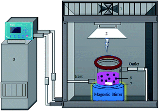 |
| | Scheme 1 Schematic illustration for the photocatalytic reactor used in the photodegradation of RhB under visible-light irradiation (λ > 420 nm) (1. suction fan, 2. Xe lamp 400 W, 3. cut-of filter, 4. cooling jacket, 5. 200 mL quartz vessel, 6. photocatalyst, 7. magnet bar, and 8. low temperature thermostat.). | |
3. Results and discussion
3.1. Morphology and structure
The crystalline structures of C–N/Nb2O5NNs and Nb2O5-CS photocatalysts were characterized by XRD which were shown in Fig. 1(a). Both products showed four peaks at 22.9°, 26.6°, 46.6°, and 55.4° that corresponded to (001), (100), (002), and (102), respectively, revealing the presence of the pseudo-hexagonal Nb2O5 structure in both catalysts (JCPDS, card no. 028-0317). No other impurity peaks were observed, suggesting the catalyst precursors maintained a uniform Nb2O5 without other phases or obvious agglomeration. The intensity ratio I(001)/I(100) of (001) peak to (100) peak was the criterion for the oriented degree of Nb2O5 nanostructures. The higher I(001)/I(100) ratio for C–N/Nb2O5NNs (19.2) compared with that of Nb2O5-CS (14.6) implied a preferentially oriented growth of nanonets along the (001) direction. We assumed that presence of Hmim enhanced the growth of the Nb2O5 nanostructures.
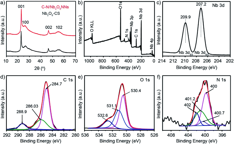 |
| | Fig. 1 (a) XRD patterns of catalyst precursors C–N/Nb2O5NNs (red) and Nb2O5-CS (black). (b) Full-scale XPS spectrum survey of C–N/Nb2O5NNs. High-resolution XPS spectrum of Nb 3d (c), C 1s (d), O 1s (e), and N 1s (f). | |
Fig. 2 displayed the typical SEM and TEM images that visualized much better the hierarchical nanostructure of C–N/Nb2O5NNs catalyst. An expansive amount of nanonets were found in the C–N/Nb2O5NNs as can be concluded from Fig. 2(a and b). TEM image, as can be seen in Fig. 2(c), further confirmed that the C–N/Nb2O5NNs were constructed using many disordered Nb2O5 nanowires with small diameters forming our nanonetstructures. Furthermore, it is reasonable to believe that the hierarchical 2D structure of Nb2O5 nanonets facilitated the diffusion of reactant molecules to be easily accessed into the active surfaces, which were useful for the enhancement of the photocatalytic performance. The SEM and TEM images confirmed that C–N/Nb2O5NNs consisted of conjugated nanowires with a diameter range of 5 to 10 nm and an average length of 100–200 nm. Moreover, the HRTEM image showed the hierarchical nanowire as a single component for the nanonetstructures with a diameter less than 10 nm at which the lattice spacing of 0.382 nm appeared perpendicular to the nanowire axis (Fig. 2(d)). This result corresponded with the d value of 0.390 nm from the XRD results in Fig. 1. Therefore, the crystal growth of C–N/Nb2O5NNs has likely followed the (001) direction in the presence of Hmim during the hydrothermal treatment. Conversely, the Nb2O5-CS was composed of irregular nanoparticles and had a rough surface compared to that of C–N/Nb2O5NNs (as can be seen in Fig. S1(a)†). The TEM image of Nb2O5-CS indicated that the irregular nanoparticles were made of numerous aggregated short nanorods with a diameter of about 10 nm (Fig. S1(b)†). Therefore, the presence of Hmim is essential in the hydrothermal synthesis of C–N/Nb2O5NNs which played an important role in the formation of Nb2O5 nanonets as a structure-directing agent.
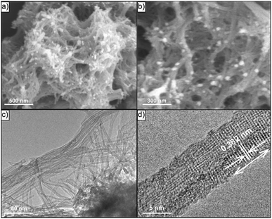 |
| | Fig. 2 Typical SEM and TEM images of C–N/Nb2O5NNs nanostructures with low resolution (a and c) and with high resolution (b and d), respectively. | |
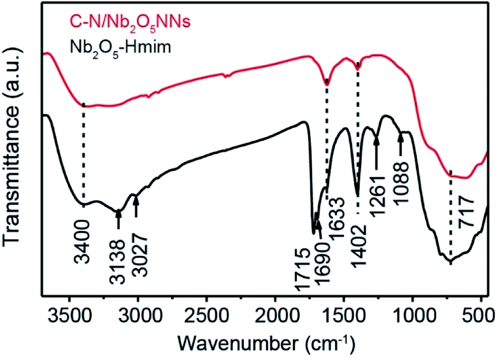
The presence of Hmim on Nb2O5 surface was a key parameter in our synthesis method prior to applying the calcination process to provide a source of C and N species. Therefore, C–N/Nb2O5NNs and Nb2O5–Hmim were investigated using FT-IR spectra Fig. 3. As presented, the typical absorption bands of imidazole were found at 1088 and 1261 cm−1 (Fig. 3 black).25 For C and N stretching vibrations, the observed peaks at 1690 cm−1 and 1715 cm−1 were ascribed to C–C stretching and oxalate precursor adhering to the Nb2O5 surface, respectively; while the observed peaks at 3138 and 3027 cm−1 occurred due to the N–H stretching vibrations. The absorption peak at 717 cm−1 was assigned to Nb–O–Nb angular vibrations and Nb![[double bond, length as m-dash]](https://www.rsc.org/images/entities/char_e001.gif) O stretching.26 In addition, the strong peak at 3400 cm−1 was due to the adsorbed H2O molecules on the sample surface. Another strong peak appearing at 1633 cm−1 was attributed to the bending vibrations of hydroxyl groups in H2O molecules.24 These findings indicated that imidazole molecules were present on the surface of the Nb2O5–Hmim (black, Fig. 3). Interestingly, the characteristic peaks for imidazole were not observed for C–N/Nb2O5NNs spectra (red, Fig. 3), showing the adsorbed imidazole molecules were completely decomposed upon catalyst calcination at 350 °C for 2 h. Furthermore, the peak at 1402 cm−1 suggested the existence of COx.27
O stretching.26 In addition, the strong peak at 3400 cm−1 was due to the adsorbed H2O molecules on the sample surface. Another strong peak appearing at 1633 cm−1 was attributed to the bending vibrations of hydroxyl groups in H2O molecules.24 These findings indicated that imidazole molecules were present on the surface of the Nb2O5–Hmim (black, Fig. 3). Interestingly, the characteristic peaks for imidazole were not observed for C–N/Nb2O5NNs spectra (red, Fig. 3), showing the adsorbed imidazole molecules were completely decomposed upon catalyst calcination at 350 °C for 2 h. Furthermore, the peak at 1402 cm−1 suggested the existence of COx.27
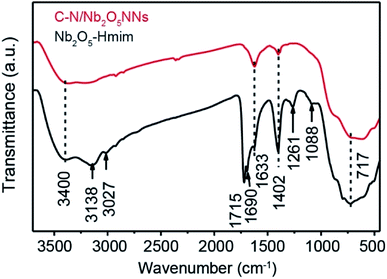 |
| | Fig. 3 FT-IR spectra of the C–N/Nb2O5NNs (red) and Nb2O5–Hmim (black). | |
The BET surface areas and porous structures of C–N/Nb2O5NNs samples were also studied using nitrogen adsorption–desorption isotherms. The N2 adsorption–desorption isotherms curve confirmed the presence of mesoporous structure in our catalysts which exhibited a type IV isotherm characteristic as can be seen in Fig. 4, suggesting the modification with C and N did not disturb the mesoporous-nanonet-structure. This observation was consistent with the XRD results, proposing that C and N were uniformly dispersed on the surface of the nanonet structure without obvious agglomeration. A distinct hysteresis loop in the P/P0 range above 0.1 (Fig. 4) indicated a wide pore size distribution in the C–N/Nb2O5NNs which can be attributed to the weave of a large amount of nanonets. Accordingly, our results showed that the pore size distributions were in the range of 0–10 nm with a mean pore size of 4.5 nm (inset, Fig. 4). This finding was in accordance with SEM and TEM observations. Furthermore, the specific surface area was estimated to be 229 m2 g−1 (Table 1), which was almost three times higher than those of one-dimensional Nb2O5 nanowires obtained by other preparation methods.28–31 The ultra-fine nanonets and fluffy hierarchical nanostructures contributed to the high specific surface area, which provided high sensitivity for light illumination and supplied many active surfaces for the adsorption of both reactants and surface hydroxyl groups to capture the photogenerated h+ and prevent e−–h+ from recombination.32
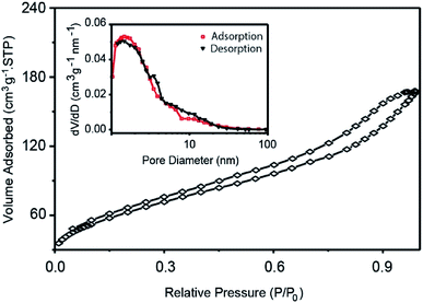 |
| | Fig. 4 N2 adsorption–desorption isotherms of C–N/Nb2O5NNs. The inset is the catalyst pore size distribution curves. | |
Table 1 Summary of the physicochemical properties, the photocatalytic activities, and the reaction rate constant, k, of C–N/Nb2O5 and Nb2O5-CS under visible light irradiation
| Sample |
Surface area (m2 g−1) |
Total pore volume cm3 g−1 |
Band gap (eV) |
RhB degradation in 30 min (%) |
k (min−1) |
| C–N/Nb2O5NNs |
229 |
0.26 |
2.90 |
99 |
0.136 |
| Nb2O5-CS |
166 |
0.37 |
3.25 |
20 |
0.006 |
3.2. XPS analysis
XPS analysis was further employed to determine the composition and surface electronic state of C–N/Nb2O5NNs. The samples were composed of 16.84 at% Nb, 31.5 at% C, 50.64 at% O, and 1.01 at% N (Fig. 1(b)). The two distinct peaks at 207.4 eV and 209.9 eV (see Fig. 1(c)) were attributed to Nb 3d5/2 and Nb 3d3/2, respectively, which correspond to the characteristic peaks of Nb5+ ions in Nb2O5.33 The high-resolution XPS spectra of C 1s in the as-prepared C–N/Nb2O5NNs were separated into three peaks; those found at 284.7 and 286.03 eV were assigned to adventitious carbon, which was formed due to the insufficient burning of organic component and contamination from the air.26 The other peak at around 288.9 eV (Fig. 1(d)) suggested the existence of COx34 which were in agreement with our results obtained by FT-IR spectrum (Fig. 3). Using the Lorentzian–Gaussian fitting method, we divided the O 1s spectrum into three peaks at 530.4, 531.1, and 532.6 eV (Fig. 1(e)). These characteristic peaks ascribed to the Nb–O bond in Nb2O5 and, the oxygen in COx and NOx, respectively.35 The binding energy peaks of N 1s (Fig. 1(f)) that centered at 400, 400.7, 401.2, and 402 eV were attributed to NOx (the oxidized state of N) existing on the surface of the as-prepared catalyst36 because NOx appeared above 400 eV.37 On the basis of the above XPS analysis, the carbon and nitrogen elements did not dope the lattice of the Nb2O5 nanonets but these species more likely attached to the surface of Nb2O5 as NOx and COx. These elements can also be eliminated through post-calcination at high temperatures, which coincided with the results of UV-vis analysis (as can be seen in the following section).
3.3. Optimization of synthesis parameters
The reaction medium conditions played a crucial role in the structure and surface morphology of our photocatalysts that directly affected on their catalytic activity performance towards RhB photodegradation processes. To obtain a better nanonet structure with a low bandgap for visible light irradiation, we investigated each parameter individually while others were fixed to unveil the optimum reaction conditions. Fig. S2† displayed the SEM images of the C–N/Nb2O5NNs synthesized using different concentrations of Hmim ranging from 15 mmol L−1 to 150 mmol L−1. At very low concentration, typically 15 mmol L−1, the catalyst nanostructure exhibited urchin-like morphology (Fig. S2(a)†), suggesting higher concentration was required for needle growing to form the nanonet structure. Interestingly, a hierarchically interconnected nanonetstructures was observed in the samples upon rising the concentration of Hmim to 30 mmol L−1 (Fig. S2(b)†). However, as Hmim concentration increased in the range of 60 mmol L−1 to 90 mmol L−1, the lengths and sizes of nanowires increased gradually and agglomerated together to form irregular nanonetstructures (Fig. S2(c and d)†). At high Hmim concentration, the nanonetstructures were completely destroyed and agglomerated (Fig. S2(e and f)†), proving that the presence of Hmim was essential in the synthesis of C–N/Nb2O5NNs as a structure-directing agent. Based on increasing the solution pH within the increasing in Hmim concentration, we argued that niobium oxalate decomposed and consequently affected the nanonets formation.24
Our results further illustrated that the increase in hydrothermal temperature and reaction time had a similar effect on the catalyst nanonetstructures. For the former, at 140 °C irregular Nb2O5 structures were obtained (Fig. 5(a)). By increasing the temperature to 160 °C, Nb2O5 exhibited needle-like structures as a sign for the beginning of nanonets formation (Fig. 5(b)). The Nb2O5 nanostructures were not observed clearly until the temperature was increased to 180 °C (Fig. 5(c)). In addition, increasing the hydrothermal temperature to 200 °C resulted in a glomeration of nanonets into compact nanostructures (Fig. 5(d)), which is possibly due to the Hmim decomposition at high temperature.38 Similarly, a significant enhancement in the structure of the Nb2O5 nanonets was found by increasing the reaction time from 1 h to 24 h (Fig. S3†). As the reaction time increased the needle-like Nb2O5 structures tended to form a hierarchical Nb2O5 nanonetstructures which perfect nanonetstructures were obtained at reaction time 24 h throughout a comprehensive series of experimental observations for the reaction time (Fig. S3(a–f)†). These observations revealed that the hydrothermal temperature and reaction time had a major effect on the synthesis of Nb2O5 nanonets in order to obtain a uniform structure.
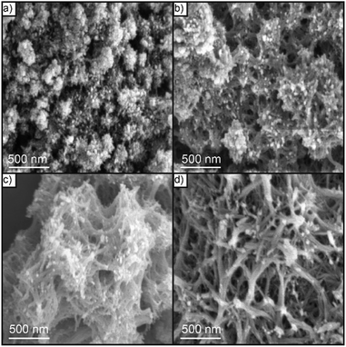 |
| | Fig. 5 SEM images of Nb2O5 nanonetstructures synthesized at different hydrothermal temperatures: (a) 140 °C, (b) 160 °C, (c) 180 °C, and (d) 200 °C. | |
The possible formation mechanism of the hierarchical Nb2O5 nanostructures was proposed on the basis of the above results and discussions. First, the introduction of 2-methylimidazole as a Lewis base39 providing a weak alkaline environment, resulting in the hydrolysis of niobium oxalate in the presence of Hmim to niobium ionic species [NbO(OH)2(C2O4)]− that further tended to form the dimeric ionic species of [Nb2O4(OH)2(C2O4)2]2−.40 The formation of the dimeric ionic species led to the creation of Nb2O5 crystal nucleus in this weak alkaline environment, suggesting a driving force for the crystal growth of nanoparticles. Thereafter, these small particles aggregated together to reduce the total surface energy through the elimination of higher surface energy faces.41–46 Finally, Nb2O5 nanowires were grown on the surface of the seeds and then interconnected together to achieve the final Nb2O5 nanonet-like structures, leading to a decrease in their surface energy.24 According to the results of FT-IR (Fig. 3), Hmim can be adsorbed on the surfaces of Nb2O5 seeds, thereby leading to the faster growth rate along the (001) direction than along the (100) orientation. With the increasing in the hydrothermal reaction time, Nb2O5 nanonets were continuously grown along the (001) orientation with higher surface energy and then progressed into nets-like Nb2O5 via “Ostwald ripening”, leading to the formation of large Nb2O5 nanonetstructures.
Inspired by the co-solvent (water/ethanol) volumetric ratios could be used to control the reduction of all-metal precursors which formed stable intermediate metal complexes to enhance the nanoparticle morphology.47,48 As displayed in Fig. S4,† the SEM images of C–N/Nb2O5NNs at different co-solvent ratio introduced a major effect of the co-solvent ratio. Typically, at the ratio of 5:1 (Fig. S4(a)†) irregular nanoparticles with a rough surface were observed meanwhile the hierarchical interconnected nanonetstructures were found to be formed at ratio of 2:1 (Fig. S4(b)†). The further increase in ethanol percentage at ratio of 1:1 led to distorting the nanostructures (Fig. S4(c)†) while completely distortion and agglomeration were observed at ratio of 1:2 (Fig. S4(d)†). Therefore, the co-solvent volumetric ratio was one of the effective parameters influencing nanonets formation.
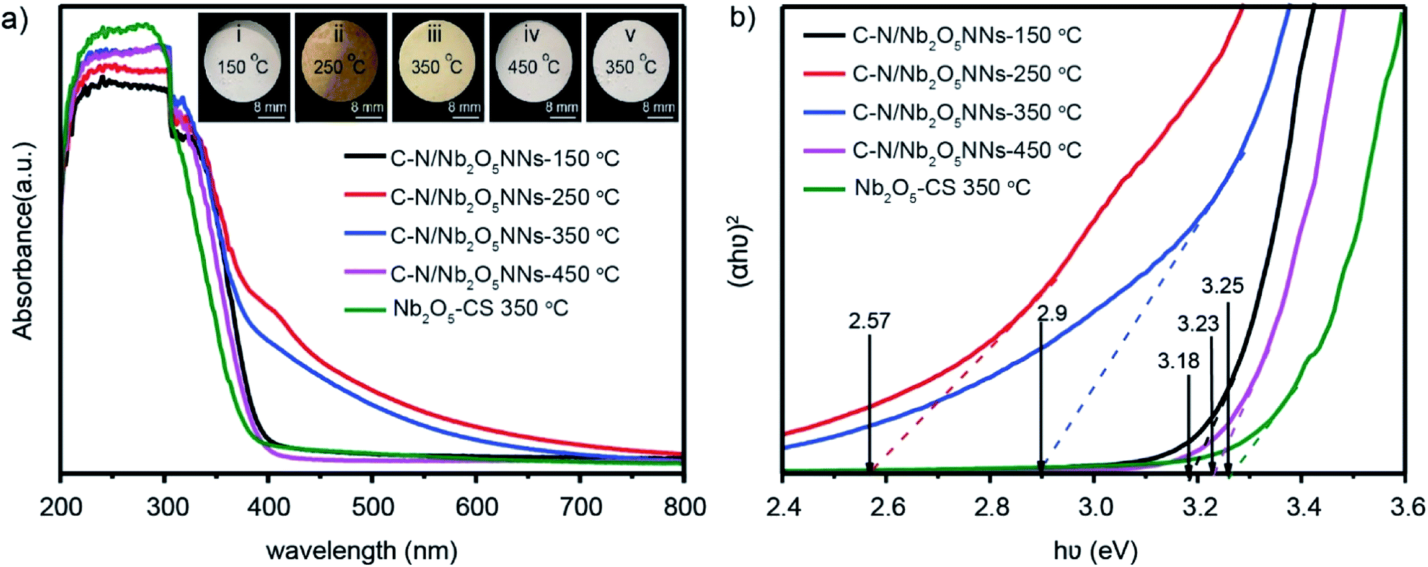
For narrowing the catalyst bandgap and enhanced the visible light absorption, the calcination temperature was investigated which directly affected the amount of C and N species on the surface of the nanostructure. Several studies showed that the calcination treatment enhanced the crystallization of nanoparticles by eliminating the organic residues from the photocatalyst surfaces.49 However, high calcination temperature can eliminate all C and N species, and lead to nanonetstructures agglomeration, providing a potential challenge to optimize the calcination temperature. At low calcination temperature of 150 °C, the organic residuals were not removed from the catalyst surface (Fig. S5(a)†) that suggested increasing the calcination temperature was necessary. As expected, at 250 °C, the process produced high N residuals on the catalyst surface (Fig. S5(b)†). Although high N residuals resulted in the lowest bandgap (Fig. 5(b)), the photocatalyst was not favourable because the high N residuals likely act as recombination centers, leading to reducing the photocurrent density.50 At 350 °C calcination temperature, further removal of N residuals from the surface was achieved, and the nanonets morphology was enhanced (Fig. S5(c)†). When the calcination temperature was increased to 450 °C, the C and N species were completely eliminated from the photocatalyst surface, and the nanonets agglomerated (Fig. S5(d)†). It is worthy of note that the amount of C and N on the surface of the as-prepared catalyst was reduced with the increasing calcination temperature, and the band gap was widened accordingly. Thus, we select the most appropriate calcination temperature of 350 °C as an optimum temperature.
3.4. Optical and photo-electrochemical properties of C–N/Nb2O5NNs
UV-vis diffusion reflectance spectra were utilized to study the optical characteristics of C–N/Nb2O5NNs-x that obtained at different calcination temperatures and of Nb2O5-CS-350 °C that obtained at 350 °C as well. The absorbance of the C–N/Nb2O5NNs-250 °C and C–N/Nb2O5NNs-350 °C samples increased in the range of 400–550 nm compared with that of C–N/Nb2O5NNs-150 °C, C–N/Nb2O5NNs-450 °C, and Nb2O5-CS (Fig. 6(a)), proving that the new absorption peak at 400–550 nm ascribed to the presence of C and N at the surface. This observation suggested that the C–N/Nb2O5NNs-250 °C and C–N/Nb2O5NNs-350 °C photocatalysts could efficiently harvest the visible light. This finding could be attributed to the synergetic effect of C and N that enhances the electron transition from an energy level of COx and NOx to the CB of the Nb2O5 nanonets.51 However, C–N/Nb2O5NNs-250 °C was excluded due to the presence of large amount of N residual on the catalyst surface (inset ii, Fig. 6(a)) which likely act as recombination centers, leading to reducing the photocurrent density.50 In addition, the corresponding energy gap (Eg) was obtained according to the plot of the transformed Kubelka–Munk function versus the energy of the exciting light [hν = A(hν – Eg)2].52 The Eg values were estimated to be 3.18, 2.57, 2.9, 3.23, and 3.25 eV for C–N/Nb2O5NNs-150 °C, C–N/Nb2O5NNs-250 °C, C–N/Nb2O5NNs-350 °C, C–N/Nb2O5NNs-450 °C, and Nb2O5-CS at 350 °C, respectively (Fig. 6(b)). These observations illustrated a wide difference in the bandgaps of C–N/Nb2O5NNs-250–450 °C which likely based on the elimination of C and N by increasing the calcination temperature, resulting in broadening the catalyst band gap. Taking together, we select the most suitable calcination temperature at 350 °C.
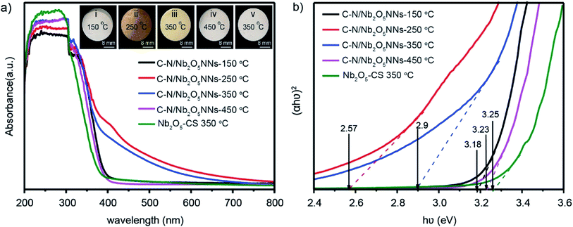 |
| | Fig. 6 (a) UV-vis diffuse reflectance spectra of the as-prepared C–N/Nb2O5NNs at different calcination temperature (150, 250, 350 and 450 °C) and Nb2O5-CS at 350 °C. The inset is Nb2O5 nanonetstructures powder at different calcination temperature: (i) 150 °C, (ii) 250 °C, (iii) 350 °C and (iv) 450 °C. (b) Plots of (αhν)2 versus (hν). | |
3.5. Photocatalytic performance
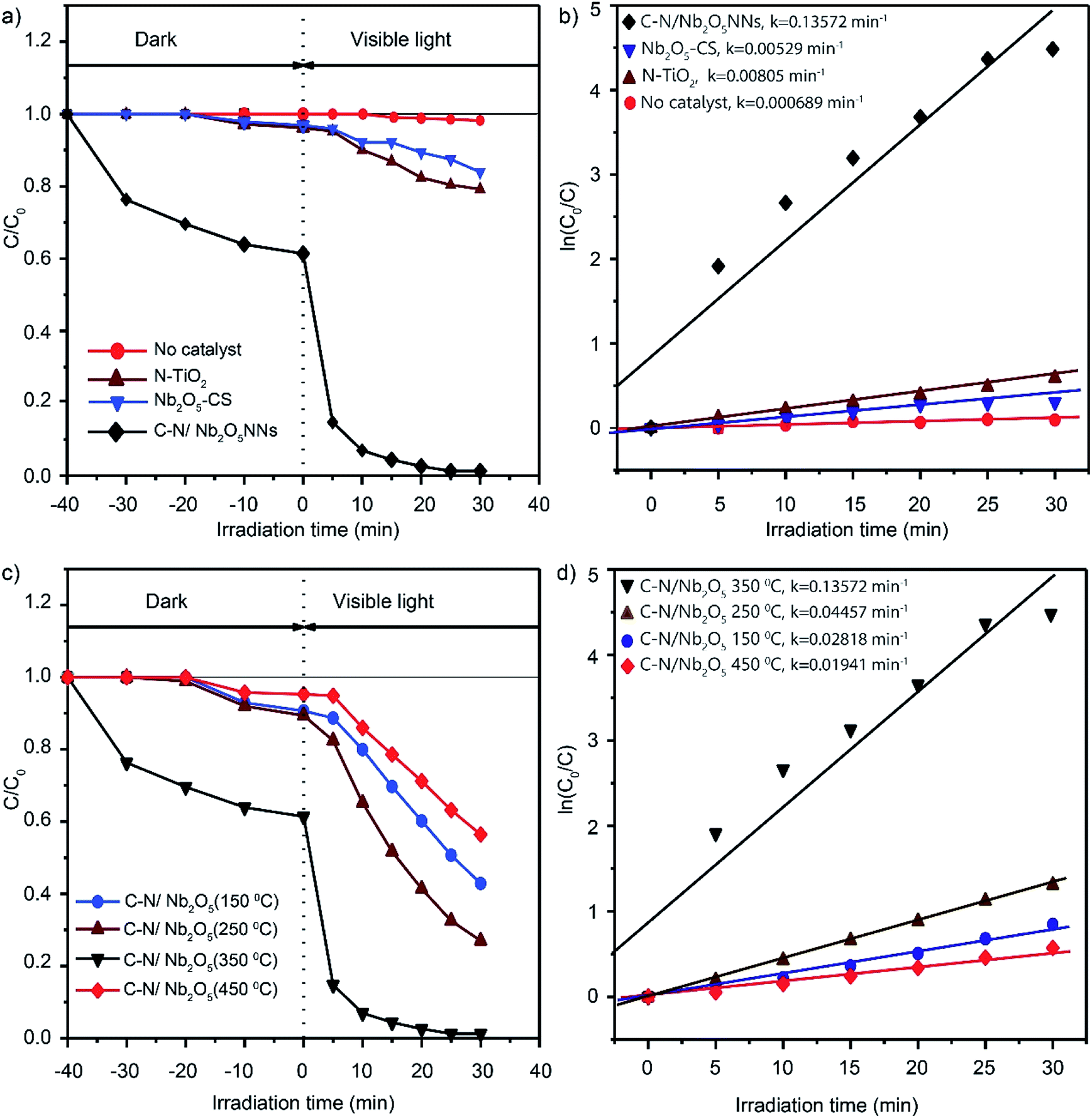
3.5.1. Photocatalytic degradation of RhB under visible light. Degradation of RhB under the visible light irradiation in aqueous solution was chosen as a photocatalytic reaction model to explore the photocatalytic activity and performance of C–N/Nb2O5NNs; meanwhile, the photocatalytic activities of N-TiO2 and Nb2O5-CS were also investigated in order to compare the performances at same conditions. The ratio of RhB residual concentration (C) and initial concentration (C0) was used to describe the degradation efficiency. Negligible photocatalytic degradation of RhB was observed which about 1.5% after 30 min under visible light irradiation without photocatalyst (red, Fig. 7(a)). It is noteworthy that the dark adsorption of C–N/Nb2O5NNs is almost 38% of RhB content, which is significantly higher than that for N-TiO2 (4.2%) and Nb2O5-CS (3.1%) (Fig. 7(a)). We assume that the high dark adsorption capacity could be attributed to the carbon modification on the surface of the catalyst53 and the relatively high specific surface area for the net-like aggregates which exhibit a high adsorption capacity towards RhB in water. These results suggest a favourable photocatalytic reaction.54 As expected, a significant photocatalytic activity was observed for C–N/Nb2O5NNs after switching on the visible light which displayed a better performance than that for N-TiO2 and Nb2O5-CS. Interestingly, RhB was about to degrade completely within 20 min by C–N/Nb2O5NNs. Conversely, N-TiO2 prepared by the urea method exhibited an extremely low photocatalytic activity; meanwhile, Nb2O5-CS showed only about 20.9% photodegradation activity, suggesting the modification with C and N species is crucial to enhance the photocatalytic performance and activity of our proposed photocatalyst. Moreover, Fig. S6(a and b)† displayed the UV-vis absorption spectra of RhB in aqueous solution for C–N/Nb2O5NNs, and Nb2O5-CS. With the increase in illumination time, the maximum absorption peaks of RhB at 554 nm were significantly decreased and shifted to a lower wavelength in case of C–N/Nb2O5NNs (Fig. S6(a)†). This result indicated that RhB solution was almost completely degraded after illumination for 30 min, and the chromophores and aromatic rings of RhB were destroyed by the C–N/Nb2O5NNs under visible light irradiation at which the RhB molecules were degraded instead of being simply decolorized.6,55
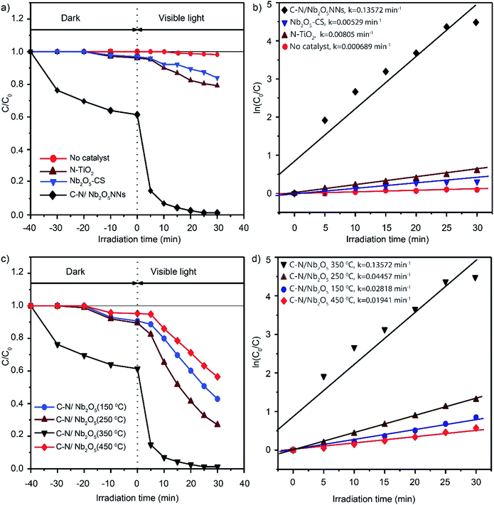 |
| | Fig. 7 Photodegradation curves of RhB in water over N-TiO2, Nb2O5-CS, and C–N/Nb2O5NNs under visible-light irradiation (λ > 420 nm) (a) and the fitting curves assuming a pseudo-first-order reaction (b). Photocatalytic degradation curves of RhB over C–N/Nb2O5NNs after calcination at different temperatures (150–450 °C) (c) and the fitting curves assuming a pseudo-first-order reaction (d). Data were recorded in 10 mg L−1 RhB dye solution in the presence of 1 g L−1 catalyst. | |
All the reaction kinetics could be fitted assuming a pseudo-first-order reaction,56,57 where the concentration of RhB molecules just after the dark adsorption–desorption equilibrium was taken as C0 while after a reaction time, t, was taken as C. Fig. 7(b) displayed the corresponding fitting results which indicated that all the degradation kinetics followed roughly the pseudo-first-order reaction. The photocatalytic activity of C–N/Nb2O5NNs was almost 25 times than that of Nb2O5-CS, and about 17 times than that of N-TiO2. These observations further suggested that COx and NOx largely played a significant role in enhancing the photocatalytic activity.
Our results further showed the importance for calcination temperature which could control the amount of organic residues in the catalyst surface within the increase in calcination temperature, leading to significant changes in our photocatalyst. Fig. 7(c) illustrated the different performances over RhB photocatalytic degradation for C–N/Nb2O5NNs within changing the calcination temperature. The outcomes generally showed that all samples had a visible light photocatalytic activity with the lowest performance for C–N/Nb2O5NNs-450 °C, corresponded to almost total elimination of C and N, and a best performance for the C–N/Nb2O5NNs-350 °C, further elucidating that the optimum calcination temperature was 350 °C. These results were consistent with the reaction rate constants investigations for C–N/Nb2O5NNs at different calcination temperatures in which the photocatalytic activity of C–N/Nb2O5NNs 350 °C was 7, 5, and 3 times than that of C–N/Nb2O5NNs 450 °C, C–N/Nb2O5NNs 150 °C, and C–N/Nb2O5NNs 250 °C, respectively (Fig. 7(d)).
3.5.2. Stability of the catalyst. Photostability, an essential characteristic in many applications towards the corresponding recycling catalysts, can confirm the stability of C–N/Nb2O5NNs for reasonable practical applications. As given in Fig. S7,† almost no change was observed in the degradation efficiency even after five cycles of RhB photodegradation in aqueous solution. These observations confirmed that the as-synthesized Nb2O5 nanonets catalysts were stable, recyclable, and an appropriate candidate for RhB photocatalytic degradation under visible light irradiation.
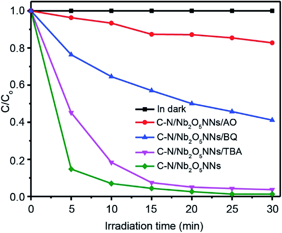
3.5.3. Photocatalysis mechanism of C–N/Nb2O5NNs. To better understand the photocatalytic mechanism for RhB degradation over the C–N/Nb2O5NNs, we designed some trapping experiments to investigate the intrinsic photocatalytic activity of our as prepared catalyst and further clarify synergetic effects of C and N, and the origin of degradation processes through trap several active intermediates, such as h+, hydroxyl radicals (·OH), and superoxide radical anion (O2˙−). The photocatalytic activities of C–N/Nb2O5NNs toward RhB degradation with different active species scavengers were shown in Fig. 8. One can see that the photocatalytic activity of C–N/Nb2O5NNs was mostly affected by adding ammonium oxalate (AO) to the working solution as it is well known that AO is h+ scavenger.58 Adding 100 mg of AO into the system led to trapping h+, resulting in a sharp decrease in the degradation activity of the catalyst which is almost 9 times lower within 10 min (red, Fig. 8) compared to the original activity of C–N/Nb2O5NNs. This observation indicated that h+ played a significant key role in the mechanism of RhB photodegradation during the photocatalysis process, illustrating the synergism between C and N, and Nb2O5N that produced large number of h+. To further investigate the role of O2˙− radicals in the mechanism of RhB photodegradation, we used Benzoquinone (BQ) as a scavenger for trapping O2˙− radicals.59 Our results showed that introducing 1 mg of BQ to the system can reduce the catalyst photodegradation activity towards RhB by almost 6 times lower within 10 min (blue, Fig. 8) compared to the original activity of C–N/Nb2O5NNs, suggesting that O2˙− radicals played a secondary role in the mechanism of RhB photodegradation. Furthermore, the catalyst photocatalytic activity slightly decreased when 2 mL of tert-butyl alcohol, a scavenger for ·OH radicals, was added into the suspension. This finding proved that the ·OH radicals have a minimal effect on the RhB photodegradation mechanism.
 |
| | Fig. 8 Photocatalytic degradation curves of RhB over C–N/Nb2O5NNs under different trapping experiments conditions. | |
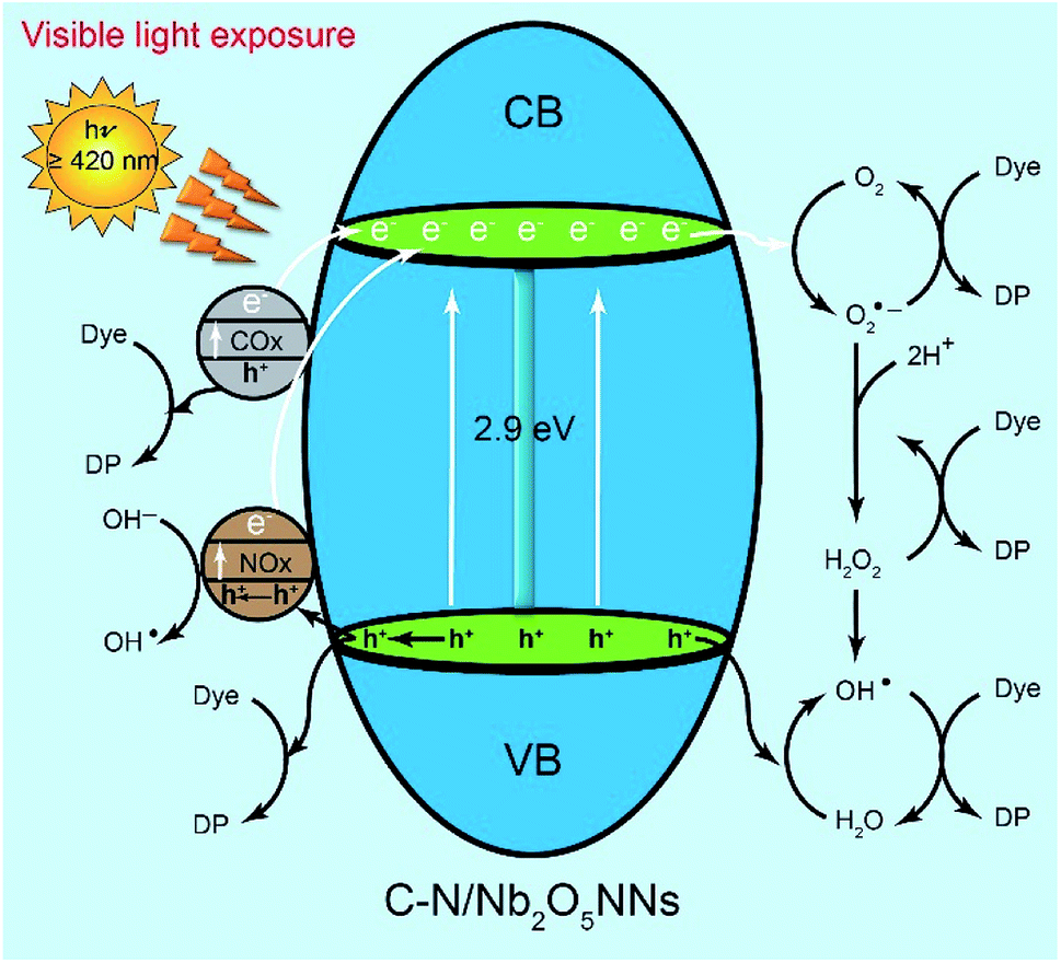
We assumed that the remarkable photocatalytic degradation of our catalyst could be attributed to some possible pathways through the RhB photodegradation mechanism. We speculated that upon visible light irradiation the optically excited electron could transfer from the COx and NOx species to the conduction band of C–N/Nb2O5NNs that further generated h+ at COx and NOx by exiting their electrons to the CB of the Nb2O5 nanonets, suggesting much more h+ as an active center for RhB degradation which were consistent with our findings that introduced h+ as a significant key role in the RhB photodegradation mechanism in Section 4.3.21,26,53,60 On the other hand, the adsorbed oxygen molecules (O2) on the surface of the catalyst can capture the CB electrons to possible formation of both O2˙− and ·OH (Scheme 2). Since ·OH and O2˙− are considered as strong oxidizing agents, they can interact with the RhB dye upon generation to form the degradation products (DP). Likewise, as RhB dye can be excited by the visible light, its excited electrons tended to jump into the CB of Nb2O5, suggesting more electrons population in the CB of the catalyst. Interestingly, NOx species as h+ trapping centers anticipated to increase the lifetime of electrons in the CB which inhibited the recombination of charge carriers and prolonged their lifetime,51,61 granting the electrons a plenty of time to efficiently interact with the adsorbed oxygen on the catalyst surface for more effective RhB degradation. One more possible active center could be attributed to the interaction of the VB's h+ with H2O in the solution to form ·OH, one of the strongest known oxidants, leading to further RhB degradation. We proposed that the generation of the active centers on the surface of C–N/Nb2O5NNs could be as follows:
| | |
C–N/Nb2O5 + visible light → e(Nb2O5)− + h(Nb2O5,COx,NOx)+
| (1) |
| | |
O2(ads) + e(Nb2O5)− → O2˙−
| (2) |
| | |
H2O2 + O2˙− → OH˙ + OH− + O2
| (4) |
| | |
h(Nb2O5, COx, NOx)+ + H2O → H+ + OH˙
| (5) |
| | |
OH˙, h(Nb2O5, COx, NOx)+, O2˙− or H2O2 + dye → degradation product (DP)
| (6) |
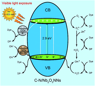 |
| | Scheme 2 Mechanism diagram of liquid-phase photocatalytic degradation of RhB over C–N/Nb2O5NNs under visible light irradiation. | |
4. Conclusions
In summary, the Nb2O5 nanonetstructures was synthesized for the first time by using a facile hydrothermal method based on Hmim as a structure-directing agent that controlled the crystal growth of Nb2O5 to form the nanonets and provided nitrogen and carbon sources for the successful fabrication of C–N/Nb2O5NNs. The synergetic effects of C and N on the surface of Nb2O5 nanonets not only led to substantially reducing the bandgap from 3.25 to 2.9 eV but also increased the population of h+, resulting in a significant enhancement in the visible light response and intensive photodegradation process. On the other hand, the significant photocatalytic activity of these nanonets in the RhB degradation under visible light irradiation could be attributed to the mutual contributions of C and N in extending the light absorption of Nb2O5 to the visible region as well, enhancing the photo-induced electron–hole pair separation efficiency, producing many oxygen vacancies, and offering a wide surface area containing accessible active sites. The outcome of active species trapping experiments proved that h+ was the most important intermediate among O2˙− and ·OH radicals during RhB photodegradation. This study proposes a synthesis method that opens a new route for a feasible and simple approach to design 2D mesoporous nanonetstructures with potential applications in catalysis, solar energy conversion, and environmental purification.
Conflicts of interest
There are no conflicts declare.
Acknowledgements
This research was supported by the National Natural Science Foundation of China (NSFC) (No. 21806037).
Notes and references
- M. A. Alpuche-Aviles, S. Gutierrez-Portocarrero and K. K. Barakoti, Curr. Opin. Electrochem., 2019, 13, 174–180 CrossRef CAS
 .
. - P. Calza, C. Massolino, G. Monaco, C. Medana and C. Baiocchi, J. Pharm. Biomed. Anal., 2008, 48, 315–320 CrossRef CAS PubMed .
- M. B. Ahmed, J. L. Zhou, H. H. Ngo, W. Guo, N. S. Thomaidis and J. Xu, J. Hazard. Mater., 2017, 323, 274–298 CrossRef CAS PubMed .
- V. R. de Mendonça, H. A. J. L. Mourão, A. R. Malagutti and C. Ribeiro, Photochem. Photobiol., 2014, 90, 66–72 CrossRef PubMed .
- P. Hu, D. Hou, Y. Wen, B. Shan, C. Chen, Y. Huang and X. Hu, Nanoscale, 2015, 7, 1963–1969 RSC .
- X. Li, N. Kikugawa and J. Ye, Adv. Mater., 2008, 20, 3816–3819 CrossRef CAS .
- T. D. Dao, M. E. Hafez, I. S. Beloborodov and H.-D. Jeong, Bull. Korean Chem. Soc., 2014, 35, 457–465 CrossRef CAS .
- S. Wang, M. Xu, T. Peng, C. Zhang, T. Li, I. Hussain, J. Wang and B. Tan, Nat. Commun., 2019, 10, 676 CrossRef PubMed .
- X. Xu, B. Tian, S. Zhang, J. Kong, D. Zhao and B. Liu, Anal. Chim. Acta, 2004, 519, 31–38 CrossRef CAS .
- S. Mujawar, A. Inamdar, S. Patil and P. Patil, Solid State Ionics, 2006, 177, 3333–3338 CrossRef CAS .
- X. Xu, B. Z. Tian, J. L. Kong, S. Zhang, B. H. Liu and D. Y. Zhao, Adv. Mater., 2003, 15, 1932–1936 CrossRef CAS .
- J. Yan, G. Wu, N. Guan and L. Li, Appl. Catal., B, 2014, 152–153, 280–288 CrossRef CAS .
- L. C. A. Oliveira, H. S. Oliveira, G. Mayrink, H. S. Mansur, A. A. P. Mansur and R. L. Moreira, Appl. Catal., B, 2014, 152–153, 403–412 CrossRef CAS .
- S.-M. Lam, J.-C. Sin, I. Satoshi, A. Z. Abdullah and A. R. Mohamed, Appl. Catal., A, 2014, 471, 126–135 CrossRef CAS .
- L. D. Gómez and J. E. Rodríguez-Páez, Nano-Struct. Nano-Objects, 2019, 17, 43–57 CrossRef .
- R. Asahi, T. Morikawa, T. Ohwaki, K. Aoki and Y. Taga, Science, 2001, 293, 269–271 CrossRef CAS PubMed .
- S. Sato, Chem. Phys. Lett., 1986, 123, 126–128 CrossRef CAS .
- X. Wang, G. Chen, C. Zhou, Y. Yu and G. Wang, Eur. J. Inorg. Chem., 2012, 2012, 1742–1749 CrossRef CAS .
- M. E. Hafez, H. Ma, W. Ma and Y.-T. Long, Angew. Chem., Int. Ed., 2019, 58, 6327–6332 CrossRef CAS PubMed .
- L. Song, W. Jing, J. Chen, S. Zhang, Y. Zhu and J. Xiong, J. Mater. Sci., 2019, 54, 3795–3804 CrossRef CAS .
- S. Ge, H. Jia, H. Zhao, Z. Zheng and L. Zhang, J. Mater. Chem., 2010, 20, 3052 RSC .
- M. Faraji, M. Yousefi, S. Yousefzadeh, M. Zirak, N. Naseri, T. H. Jeon, W. Choi and A. Z. Moshfegh, Energy Environ. Sci., 2019, 12, 59–95 RSC .
- H. Liu, N. Gao, M. Liao and X. Fang, Sci. Rep., 2015, 5, 7716 CrossRef CAS PubMed .
- Y. Wang, F. Xin, X. Yin, Y. Song, T. Xiang and J. Wang, J. Phys. Chem. C, 2018, 122, 2155–2164 CrossRef CAS .
- B. Hachuła, M. Nowak and J. Kusz, J. Chem. Crystallogr., 2010, 40, 201–206 CrossRef .
- J. Xue, R. Wang, Z. Zhang and S. Qiu, Dalton Trans., 2016, 45, 16519–16525 RSC .
- A. K. Kulkarni, C. S. Praveen, Y. A. Sethi, R. P. Panmand, S. S. Arbuj, S. D. Naik, A. V. Ghule and B. B. Kale, Dalton Trans., 2017, 46, 14859–14868 RSC .
- X. Wang, C. Yan, J. Yan, A. Sumboja and P. S. Lee, Nano Energy, 2015, 11, 765–772 CrossRef CAS .
- H. Zhang, Y. Wang, P. Liu, S. L. Chou, J. Z. Wang, H. Liu, G. Wang and H. Zhao, ACS Nano, 2016, 10, 507–514 CrossRef CAS PubMed .
- K. Saito and A. Kudo, Dalton Trans., 2013, 42, 6867 RSC .
- Y. Zhao, C. Eley, J. Hu, J. S. Foord, L. Ye, H. He and S. C. E. Tsang, Angew. Chem., Int. Ed., 2012, 51, 3846–3849 CrossRef CAS PubMed .
- S. Guo, X. Zhang, Z. Zhou, G. Gao and L. Liu, J. Mater. Chem. A, 2014, 2, 9236–9243 RSC .
- Z. Dai, H. Dai, Y. Zhou, D. Liu, G. Duan, W. Cai and Y. Li, Adv. Mater. Interfaces, 2015, 2, 1500167 CrossRef .
- T. Ohno, T. Tsubota, K. Nishijima and Z. Miyamoto, Chem. Lett., 2004, 33, 750–751 CrossRef CAS .
- T. Jirsak, J. Dvorak and J. A. Rodriguez, Surf. Sci., 1999, 436, L683–L690 CrossRef CAS .
- J. R. Pels, F. Kapteijn, J. A. Moulijn, Q. Zhu and K. M. Thomas, Carbon, 1995, 33, 1641–1653 CrossRef CAS .
- Z. Zhang, X. Wang, J. Long, Q. Gu, Z. Ding and X. Fu, J. Catal., 2010, 276, 201–214 CrossRef CAS .
- M. K. Trivedi, A. B. Dahryn Trivedi and G. N. Gunin Saikia, Nat. Prod. Chem. Res., 2015, 03, 1000187 Search PubMed .
- C. Lindner, R. Tandon, B. Maryasin, E. Larionov and H. Zipse, Beilstein J. Org. Chem., 2012, 8, 1406–1442 CrossRef CAS PubMed .
- J.-M. Jehng and I. E. Wachs, J. Raman Spectrosc., 1991, 22, 83–89 CrossRef CAS .
- J. Liu, X. Huang, Y. Li, K. M. Sulieman, X. He and F. Sun, Cryst. Growth Des., 2006, 6, 1690–1696 CrossRef CAS .
- W. Shi, C. Wang, H. Wang and H. Zhang, Cryst. Growth Des., 2006, 6, 915–918 CrossRef CAS .
- C. Pacholski, A. Kornowski and H. Weller, Angew. Chem., Int. Ed., 2002, 41, 1188–1191 CrossRef CAS PubMed .
- Y. Chang, J. J. Teo and H. C. Zeng, Langmuir, 2005, 21, 1074–1079 CrossRef CAS PubMed .
- Y. Chang and H. C. Zeng, Cryst. Growth Des., 2004, 4, 273–278 CrossRef CAS .
- H. Zhu, X. Wang, F. Yang and X. Yang, Cryst. Growth Des., 2008, 8, 950–956 CrossRef CAS .
- W.-C. Chen, V. Tunuguntla, M.-H. Chiu, L.-J. Li, I. Shown, C.-H. Lee, J.-S. Hwang, L.-C. Chen and K.-H. Chen, Sol. Energy Mater. Sol. Cells, 2017, 161, 416–423 CrossRef CAS .
- J. Zhou, G. Tian, Y. Chen, Y. Shi, C. Tian, K. Pan and H. Fu, Sci. Rep., 2015, 4, 4321 CrossRef .
- Y. Hu, H. Liu, X. Kong and X. Guo, J. Nanosci. Nanotechnol., 2014, 14, 3532–3537 CrossRef CAS PubMed .
- B. Yu, W. M. Lau and J. Yang, Nanotechnology, 2013, 24, 335705 CrossRef PubMed .
- Y. Cao, Y. Cao, Y. Yu, P. Zhang, L. Zhang and T. He, Sep. Purif. Technol., 2013, 104, 256–262 CrossRef CAS .
- H. Huang, C. Wang, J. Huang, X. Wang, Y. Du and P. Yang, Nanoscale, 2014, 6, 7274–7280 RSC .
- H. Liu, Y. Wu and J. Zhang, ACS Appl. Mater. Interfaces, 2011, 3, 1757–1764 CrossRef CAS PubMed .
- Q. Jin, W. Wen, J. Q. Bai and J. M. Wu, Thin Solid Films, 2019, 683, 111–117 CrossRef CAS .
- W. Dong, F. Pan, Y. Wang, S. Xiao, K. Wu, G. Q. Xu and W. Chen, Appl. Surf. Sci., 2017, 392, 514–522 CrossRef CAS .
- X.-B. Xiang, Y. Yu, W. Wen and J.-M. Wu, New J. Chem., 2018, 42, 265–271 RSC .
- Y. Xu, W. Wen and J.-M. Wu, J. Hazard. Mater., 2018, 343, 285–297 CrossRef CAS PubMed .
- N. Zhang, Y. Zhang, M.-Q. Yang, Z.-R. Tang and Y.-J. Xu, J. Catal., 2013, 299, 210–221 CrossRef CAS .
- J. Wang, P. Wang, Y. Cao, J. Chen, W. Li, Y. Shao, Y. Zheng and D. Li, Appl. Catal., B, 2013, 136–137, 94–102 CrossRef CAS .
- D. Mitoraj and H. Kisch, Chem.–Eur. J., 2010, 16, 261–269 CrossRef CAS PubMed .
- Y. Chang, J. J. Teo and H. C. Zeng, Langmuir, 2005, 21, 1074–1079 CrossRef CAS PubMed .
Footnote |
| † Electronic supplementary information (ESI) available. See DOI: 10.1039/c9ra07505d |
|
| This journal is © The Royal Society of Chemistry 2019 |
Click here to see how this site uses Cookies. View our privacy policy here. 
 Open Access Article
 This Open Access Article is licensed under a Creative Commons Attribution-Non Commercial 3.0 Unported Licence
 a,
Samah A. Mahyoub
a,
Samah A. Mahyoub