 Open Access Article
Sulfonic SiO2 nanocolloid doped perfluorosulfonic acid films with enhanced water uptake and inner channel for IPMC actuators
Yubing Hana,
Fang Wanga,
Hongkai Lib,
Erchao Menga,
Shaoming Fanga,
Ansha Zhaoc and
Dongjie Guo *a
*a
aState Laboratory of Surface & Interface, Zhengzhou University of Light Industry, Zhengzhou, 450002, China. E-mail: djguo@zzuli.edu.cn
bCollege of Mechanical and Electrical Engineering, Nanjing University of Aeronautics and Astronautics, Nanjing, China 210016
cKey Laboratory of Advanced Technologies of Materials, Ministry of Education, SWJTU, Chengdu, China 610036
First published on 20th December 2019
Abstract
This study provides a facile and effective strategy to fabricate sulfonic SiO2 nanocolloid (HSO3–SiO2) doped perfluorosulfonic acid (PFSA) films with enhanced water uptake and inner channel for high-performance and cost-effective ionic exchange polymer metal composite (IPMC) actuators. A commercial precursor of mercaptopropyl trimethoxysilane was hydrolyzed to form thiol functionalized SiO2 nanocolloids (SH–SiO2, ∼25 nm in diameter), which were further oxidized into sulfonic SiO2 nanocolloids (HSO3–SiO2, ∼14 nm in diameter). Both SiO2 nanocolloids were used as additives to dope PFSA film for fabricating IPMC-used matrix films. Due to difference of compatibility, the SH–SiO2 nanocolloids take phase separation in the cocrystallization course, and aggregate into huge, regular spherical particles with a mean diameter of ∼690 μm; while the HSO3–SiO2 nanocolloids are completely compatible with PFSA, forming a very homogeneous hybrid matrix film. Related physiochemical investigations by analytical tools revealed that, the resultant HSO3–SiO2 hybrid film shows better IPMC-related properties compared to the SH–SiO2 hybrid film: 1.59 folds in water uptake, and 2.37 folds in ion exchanging capacity, thus contains an increased number of cations and possesses larger and better interconnected inner channels for IPMC bending. Consequently, the HSO3–SiO2 hybrid IPMC actuator exhibits remarkably higher levels of actuation behaviours such as higher force output, higher displacement output, and longer stable working time, which could be used as a valuable artificial muscle for flexible actuators or displacement/vibration sensors at low cost.
Introduction
Ion-exchange polymer metal composites (IPMCs) are flexible actuators made of smart materials that respond to deformation based on external electrical stimulation.1–4 Due to high energy density and large displacement output under very low driving voltages (usually less than 5.0 V), they are widely used in biomimic robotic actuators, artificial muscle, and dynamic sensors.5–11 For conventional IPMC actuators, an ion exchanging film such as perfluorosulfonic acid (PFSA, a commercial name of Nafion) or perfluorocarboxylic acid, is sandwiched between two inert metal (typically Pt) sheets as working electrodes. When an electric field is applied, force and displacement are generated due to the migration of hydrated cations in inner channels.12 According to this actuation mechanism, IPMC's electromechanical response is closely related to migration rate of the hydrated cations, which depends on water uptake (WU) of the matrix film. However, the pure PFSA film always exhibits a poor hydrophilicity, cannot save much water for supporting IPMC actuation longtime in air, thus limits its commercial applications. Hydrophilic silicate species such as SiO2 particles and montmorillonite (MMT) flakes were commonly used additives to improve the WU of PFSA matrix as well as its mechanical performance, and those hybrid IPMC actuators therefore exhibited enhanced force output and elongated stable actuation time.13–17The main chain of DuPont PFSA is a linear hydrophobic structure, which takes microphase separation and crystallizes into a non-ionic phase; conversely, the branch chains of sulfonic groups are hydrophilic, and form an ionic phase with adsorbed water molecules.18,19 Ionic domains aggregate to form inner channels, allowing hydrated cations to migrate. Thus the matrix film containing more sulfonic acid or carboxylic acid groups can produce larger and better interconnected inner channels for ion migration.20 DuPont PFSA possesses a varying ion exchanging capacity (IEC) of 0.90–1.05 mmol g−1, usually forms inner channels with varying diameters of 4–5 nm.21 To further enhance IEC, many sulfonic additives such as sulfonic acid functionalized polystyrene,22–24 graphene oxide,25 carbon nanotubes,26,27 poly(ether ether ketone),28 and polysulfone29,30 were doped to fabricate hybrid IPMC actuators with improved electromechanical behaviours.
Sulfonic acid functionalized SiO2 might be a most promising additive considering its high WU and IEC. Former papers had reported the preparation techniques of Nafion hybrid films containing sulfonic SiO2 additives for applications in direct methanol fuel cells.31–33 Li's group doped fumed silica into Nafion and then grafted sulfonic acid on the silica surface by sulfonation of concentrated H2SO4, the resultant composite film exhibited good ionic current and proton conductivity.32 Ren' group introduced active thiol group into the silica doped Nafion, and then conversed the –SH group to the –SO3H group by oxidization.33 The resultant hybrid film exhibited enhanced mechanical properties, but endured shortages of low IEC and proton conductivity, when compared to the pure Nafion film.
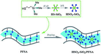
Herein, we developed a facile and effective strategy to fabricate sulfonic SiO2 doped PFSA (HSO3–SiO2/PFSA) film with enhanced WU and IEC. As shown in Fig. 1, a commercial thiol precursor of mercaptopropyl trimethoxysilane was hydrolyzed to form thiol functionalized SiO2 nanocolloids (SH–SiO2), which were further oxidized into sulfonic SiO2 nanocolloids (HSO3–SiO2) for using as additive of PFSA. Because the sulfonic acid group is rather compatible with PFSA, no evident phase separation happened during the cocrystallization course, and a very homogeneous copolymer film of HSO3–SiO2/PFSA was yielded. Related physiochemical investigations by analytical tools revealed that, this new hybrid film exhibited high WU, strong IEC, and fast Li+ ion conductivity, without a sacrifice of mechanical strength, which can be used to fabricate high-performance and cost-effective IPMC actuators. We therefore provide a practical technique to fabricate commercialized actuators or displacement/vibration sensors at low cost.
Experimental section
Materials
Perfluorosulfonic acid solution (DuPont DE-2021, 20 wt%) with a total acid capacity of 0.95 meq. g−1 was purchased from DuPont Company. Poly(dimethylsiloxane) (PDMS, Sylgard 184) was obtained from Dow Corning (Midland, USA). Pt(NH3)4Cl2, (3-mercaptopropyl)trimethoxysilane (KH590), H2O2 (30 wt%), dry ethanol and dimethyl formamidine (DMF) were obtained from Sigma Aldrich.Preparation and characterization of sulfonic silica nanocolloids
Thiol functionalized SiO2 nanocolloids (SH–SiO2) were prepared by hydrolysis of the precursor KH590. 2.0 mL of pure KH590 was added into a mixture containing 18.0 mL of ethanol and 2.0 mL of deionized water (pH = 2.0), this mixture was permitted to react for 90 min at 80 °C under violently stirring. After complete hydrolysis of the KH590, the product was dialysed in anhydrous ethanol three times to remove excess water (weight cutoff of the dialysis bag was 300). Finally, the solution was concentrated to 2.0 mL by a rotating evaporator, thus obtaining a colorless and transparent colloid solution containing around 1.08 g SH–SiO2 nanocolloids.Prior to concentrating, 20.0 mL of hydrogen peroxide (30%) was added into the above mixture for oxidizing the –SH. The oxidation reaction was performed under 60 °C for 24 h, then the resultant mixture was concentrated to 2.0 mL. A colorless and transparent colloid solution containing around 1.59 g HSO3–SiO2 nanocolloids was yielded.
Both the SH–SiO2 and HSO3–SiO2 nanocolloids were observed by transmission electron microscopy (TEM, JEM-2100) for morphology characterization. To obtain their chemical component information, they were dropped onto a glass slide, drying for X-ray photoelectron spectroscopy (XPS, ESCA Multilab 2000) and (ATR-FTIR, Bruker IFS66/S) analyses.
Preparation and characterization of PFSA hybrid films
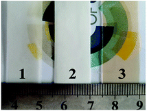
The PFSA hybrid films were prepared by cocrystallization of PFSA with the functionalized SiO2 nanocolloids. 1.0 mL concentrated SH–SiO2 or HSO3–SiO2 colloid solution was added into two mixtures containing 18.0 mL of PFSA (20 wt%) and small amount of DMF. The mixtures were vigorously stirred for uniformly mixing, and respectively poured into two self-made PDMS-based containers (75 × 80 × 50 mm3), followed by crystallizing via solvent removal at 60 °C for 48 h. A SH–SiO2/PFSA hybrid film (white color, ∼0.46 mm thickness) and a HSO3–SiO2/PFSA hybrid film (light yellow color, ∼0.38 mm thickness) were obtained (Fig. 2). For comparison, 18.0 mL of PFSA solution was poured into the above container to make a pure PFSA film (control, white color, ∼0.31 mm thickness). To study the relationship between film thickness and electromechanical property, two other HSO3–SiO2/PFSA hybrid films with different thicknesses of 0.34 and 0.41 mm were prepared by using 0.50 and 1.50 mL HSO3–SiO2 solution. All PFSA films were annealed at 150 °C for 5 min before use.Surface chemical component and electronic structure of PFSA family films were detected by high resolution XPS. Young's modulus, IEC, WU, and water contact angle (CA) of the matrix films were determined refer to our former reports.34,35 The PVDF films were grounded into pieces for thermogravimetric analyses (TG, SDTQ600). All samples were heated from the room temperature to 800 °C at a heating rate of 10 °C min−1 under N2.
Morphology characterizations and performance measurements of IPMCs
Refer to former literatures, the PFSA matrix films were deposited Pt nano electrodes for fabricating IPMCs.17,36 To generate a stronger electrochemical response, IPMCs were incubated in a LiOH (0.05 mol L−1) solution before usage. Surface morphologies of IPMCs were detected by a field emission scanning electron microscope (FESEM) (S4800, Hitachi, Japan) using a Schottky field emission source. The IPMC samples were placed into the liquid nitrogen for 30 min, and then broken. Before SEM observation, samples were deposited by gold particles (∼5 nm) for conductivity.The electromechanical behaviours of the three IPMC actuators were determined by our custom system, which consists of a signal generator, a signal amplifier, a force sensor, and a laser displacement sensor. The signal generator has a multifunction data acquisition card (NI, 6024E), which can produce electrical signals with frequencies in the range of 0.1–100 Hz, voltages in the range of 0–10 V, and different waveforms (square, sinusoid and triangle). A force sensor with a sensitivity of 0.1 mN (CETR-UMT) and a laser displacement sensor with a sensitivity of 0.1 μm (LK-G80) were used to acquire force and displacement data. The IPMC end was aligned with the tip of the force sensor in an equilibrium position and collected the blocking force from one side. All IPMC samples were cut in same size of (30 × 5 mm2) to detect and compare their electromechanical properties.
Results and discussion
Morphology and component characterizations of functionalized SiO2 nanocolloids
Fig. 3a and b present similar, amorphous capsule structures of the SH–SiO2 and HSO3–SiO2 nanocolloids. Because the latter possesses a higher dispersibility in the polar environment (mixture of ethanol and water) as compared to the former, its mean dimension (∼14 nm) is lower than that of the former (∼25 nm), showing much finer nanocolloids. IR and XPS analyses confirm the chemical component of both nanocolloids, and are shown in Fig. 3c and d. For the IR of SH–SiO2, appearances of a broad Si–OH stretching at 3432 cm−1 and a double Si–O–Si stretching at 1113 and 1065 cm−1 suggest that the KH590 was hydrolyzed by water. After oxidation by H2O2, a complete disappearance of S–H stretching band at 2550 cm−1 and appearances of three new bands (S![[double bond, length as m-dash]](https://www.rsc.org/images/entities/char_e001.gif) O asym stretching at 1156 cm−1, S
O asym stretching at 1156 cm−1, S![[double bond, length as m-dash]](https://www.rsc.org/images/entities/char_e001.gif) O sym stretching at 1032 cm−1, and O
O sym stretching at 1032 cm−1, and O![[double bond, length as m-dash]](https://www.rsc.org/images/entities/char_e001.gif) S
S![[double bond, length as m-dash]](https://www.rsc.org/images/entities/char_e001.gif) O asym stretching at 1352 cm−1) demonstrate the successful oxidation of the thiol group.37 Additionally, sharp peaks in the range 2800–3000 cm−1 are resulted from the propyl chain of the organic linker; a stronger, broader O–H band appears at the curve of HSO3–SiO2, showing that the sulfonic acid group has a stronger affinity to water compared to its precursor.
O asym stretching at 1352 cm−1) demonstrate the successful oxidation of the thiol group.37 Additionally, sharp peaks in the range 2800–3000 cm−1 are resulted from the propyl chain of the organic linker; a stronger, broader O–H band appears at the curve of HSO3–SiO2, showing that the sulfonic acid group has a stronger affinity to water compared to its precursor.
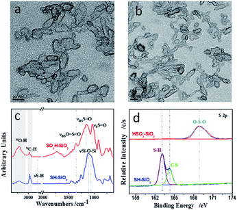 | ||
| Fig. 3 TEM images of (a) SH–SiO2 nanocolloids, and (b) HSO3–SiO2 nanocolloids; comparisons of (c) ATR-FTIR spectra and (d) high resolution S 2p XPS spectra. | ||
The successful oxidation of thiol group is further confirmed by XPS detection. Fig. 3d and Table 1 recorded the high resolution S 2p XPS data of both SiO2 nanocolloids. For the SH–SiO2 nanocolloids, the S 2p spectra consists of two components at 163.1 and 164.4 eV, resulting from the sulfur with a valence of −2, the former peak is derived from the S–H bond, while the latter peak is derived from the C–S bond.38,39 For the HSO3–SiO2 nanocolloids, a broad peak belongs to the sulfur with a valence of +6, resulting from sulfonic acid group. Collectively, the above results confirm the successful preparation of the sulfonic SiO2 nanocolloids.
| Sample | Atomic concentration (atom%) | |||||
|---|---|---|---|---|---|---|
| C | O | Si | F | S(II) | S(VI) | |
| SH–SiO2 | 65.73 | 24.75 | 6.86 | 0 | 2.66 | 0 |
| HSO3–SiO2 | 65.46 | 25.98 | 6.67 | 0 | 0 | 1.89 |
| Pure PFSA | 35.33 | 8.11 | 0.18 | 54.29 | 0 | 2.09 |
| SH–SiO2/PFSA | 32.91 | 9.64 | 1.52 | 53.19 | 0.36 | 2.38 |
| HSO3–SiO2/PFSA | 31.87 | 10.53 | 2.22 | 52.31 | 0 | 3.07 |
XPS characterizations of PFSA hybrid films
Fig. 4 and Table 1 compare the XPS data from the PFSA family films. Peaks of C 1s, S 2p, O 1s, F 1s, and Si 2p are shown in their survey scan curves (Fig. 4a). For the high resolution S 2p spectrum (Fig. 4b), a peak of sulfonic acid group appears at 168.6 eV, resulting from the exposed PFSA; after doping the SH–SiO2 nanocolloids, a new peak of S–H group appears at 163.2 eV; after doping the HSO3–SiO2 nanocolloids, only an enhanced peak of sulfonic acid group remains with enhanced S element concentration increasing from 2.74% to 3.07% (Table 1), this increase is resulted from the doping of sulfonic additives. For the high resolution Si 2p spectrum (Fig. 4c), no Si signal is seen for the control, while a strong Si–O–Si signal appears at 103.0 eV in both hybrid film curves, generating from the additives of SiO2 nanocolloids.40 Si element concentration varies from 1.52% of the SH–SiO2/PFSA film to 2.22% of the HSO3–SiO2/PFSA film, the change was derived from the different aggregation states of Si. Additional information such as decreases of C and F elemental concentrations and increase of O elemental concentration further confirm the doping of functionalized SiO2 nanocolloids (Fig. 4d–f, Table 1).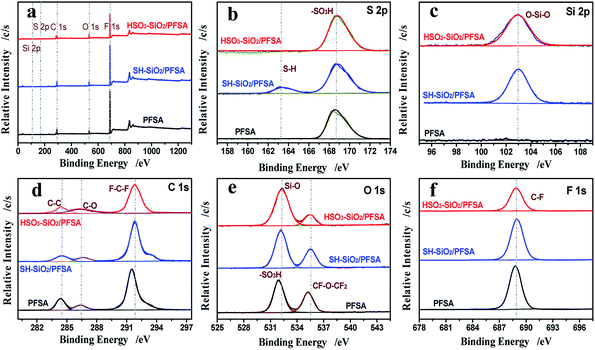 | ||
| Fig. 4 XPS analyses. Survey scans of the PFSA, SH–SiO2/PFSA, HSO3–SiO2/PFSA films (a); high resolution XPS spectra of S (b), Si (c), C (d), O (e), and F (f) elements. | ||
IPMC-related property characterizations
Introduction of functionalized SiO2 nanocolloids significantly changes the matrix film's polarity, WU, IEC, and mechanical property, thus affecting IPMC's electromechanical performance.31–35,41 The detected water CAs are 84.1, 75.7, and 54.5° for the pure PFSA, SH–SiO2/PFSA, and HSO3–SiO2/PFSA films, respectively (Fig. 5a and Table 2), thus both hybrid films become more hydrophilic due to additions of SiO2 nanocolloids, whose surfaces widely distribute hydrophilic Si–OH and Si–O–Si groups. The HSO3–SiO2/PFSA film exhibits the best hydrophilicity among those films due to the strong polarity of sulfonic acid function.| Samples | Thickness/mm | PFSA concentration/% | CA/° | WU/% | IEC/mmol g−1 | Young's moduli/MPa | Tdec of backbone/°C | |
|---|---|---|---|---|---|---|---|---|
| Dry | Wet | |||||||
| Pure PFSA | 0.31 | 100 | 84.1 | 17.9 | 0.89 | 714 | 221 | 438 |
| SH–SiO2/PFSA | 0.46 | 87.0 | 75.7 | 20.3 | 0.70 | 804 | 216 | 446 |
| HSO3–SiO2/PFSA | 0.38 | 81.8 | 54.5 | 32.2 | 1.66 | 1135 | 83 | 464 |
Data of WUs exhibit similar changing trend to CAs: WU of the HSO3–SiO2/PFSA film is higher than that of the SH–SiO2/PFSA film, which is higher than that of the control (Table 2). The detected WU of the HSO3–SiO2/PFSA film is 32.2%, increasing by 1.80 folds when compared to the control. Notably, water-driven IPMC actuators always experience water shortage due to significant evaporation and electrolysis when the hydrated cations move fast between two electrodes.34,35 Thus, high WU is important to ensure their actuation stability.
Because the sulfonic acid group possesses a strong ionization ability, the pure HSO3–SiO2 has a remarkably theoretic IEC of 6.76 mmol g−1, given the SH group is completely conversed to the SO3H group. In our experiment, the HSO3–SiO2/PFSA film exhibits a detected IEC of 1.66 mmol g−1, which is around 1.90 folds of the self-casting pure PFSA, or 1.86 folds of the commercial Nafion film.42,43 But for the SH–SiO2/PFSA film, because Si–OH and Si–SH hardly provide ion exchanging ability, its detected IEC is only 0.70 mmol g−1, which is even lower than the control of 0.89 mmol g−1. It should be noted that, the enhanced IEC would provide more inner channels, which benefits numerous ions migrating at the same time, thus might produce strong force and power outputs.44
To evaluate the compatibility between SiO2 additives and PFSA matrix films, mechanical properties of the resultant hybrid films were detected by a nanoindenter. Fig. 5b and c show the typical stress–strain curves and the calculated Young's moduli, while their detailed parameters are shown in Table 2. Clearly, all PVDF films exhibit a linear elastic region followed by a nonlinear deformation. In the dry state, the self-casting, pure control film shows a compressive Young's modulus of 714 MPa, which is higher than the commercial Nafion film of around 220 MPa in same membrane thickness.45 After doping functionalized SiO2 nanocolloids, the mechanical properties get apparently improved, the detected Young's moduli are 804 MPa for the SH–SiO2/PFSA film and 1135 MPa for the HSO3–SiO2/PFSA film, respectively increasing to 1.13 and 1.59 folds compared to the control. Thus the HSO3–SiO2/PFSA film shows the strongest mechanical strength among these films, indicating a good compatibility between the HSO3–SiO2 nanocolloids and the PFSA. After absorbed water, all three matrix films exhibit attenuated mechanical properties. Due to high hydrophilicity and WU, the HSO3–SiO2/PFSA film exhibits the lowest yield modulus of 83 MPa in the wet state, only 7.3% remains compared to the value in the dry state, suggesting a high flexibility, therefore the HSO3–SiO2/PFSA IPMC is expected to generate larger deformation.
Fig. 4 compares the thermal properties of the three matrix films. For the control, three stages of weight losses, respectively beginning at 285, 399, and 438 °C, correspond to the thermal decomposition temperatures (Tdec) of sulfonic group, branch chain, and C–F backbone. After embedded the SH–SiO2 particles, those Tdec data get evidently increased, shifting to 355, 405, and 446 °C, respectively. But for HSO3–SiO2/PFSA, only one strong weight loss at 464 °C is found, showing a high thermal stability of the HSO3–SiO2/PFSA film. Increases of Tdec hint a presence of strong interactions between the HSO3–SiO2 nanocolloids and the PFSA, further demonstrates a high compatibility between them.
IPMC morphology characterizations
Fig. 6 records and compares SEM morphologies of the two hybrid film IPMCs. As shown in Fig. 6a and d, the total thicknesses including Pt nanosheets and the matrix film are 570 μm for the SH–SiO2/PFSA based IPMC and 455 μm for the HSO3–SiO2/PFSA based IPMC. Because the latter matrix film has a higher IEC, more Pt precursor ions of [Pt(NH3)4]2+, which act as counter cations to balance the sulfuric acid anions, were absorbed and reduced into the Pt nanograins. As a result, the HSO3–SiO2/PFSA based IPMC presents a thicker Pt electrode. Notably, increasing the electrode thickness of IPMC benefits to overcome the electrode defects, and improve the electronic conductivity and “granular damming effect”.46,47 What is important, an evident transition layer generates from the interface between Pt electrode and the polymer matrix in HSO3–SiO2/PFSA based IPMC (Fig. 6e), while nearly nothing is found in SH–SiO2/PFSA based IPMC (Fig. 6b). This result hints that, a more stable connection was yielded between the Pt nanosheets and the HSO3–SiO2/PFSA matrix, which would prevent the separation of Pt nanograins from the matrix surface and ensure a stable electromechanical response.48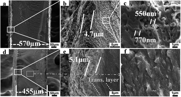 | ||
| Fig. 6 SEM image. Cross section profiles, interface connections, matrix morphologies of the SH–SiO2/PFSA (a–c) and HSO3–SiO2/PFSA (d–f) based IPMCs. | ||
A striking difference generates from the Fig. 6c and f the SH–SiO2/PFSA, many isolated spherical particles and closed pores with a mean dimension of around 690 μm are observed (Fig. 6c). Those huge spherical particles should be the SH–SiO2 particles, which were generated from the microphase separation during cocrystallization course. Because the SH–SiO2 nanocolloids are not compatible with the PFSA, they would aggregate together forming the huge spherical particles.35 Induced by the exterior polar, protonic environment, the hydrophilic Si–OH group should be exposed outside and produces H-bond interaction with the sulfonic acid group from PFSA, while the lower hydrophilic group of thiol should be buried inside. Supposed this hybrid film is oxidized by H2O2 in situ, only the naked, small amount thiol groups get opportunity of oxidation and turn into sulfonic acid groups, most of thiol groups can not be oxidized. Clearly, this strategy can not produce high IEC film.
Those closed pores generated from the removal of the SH–SiO2 particles, which might happen during the nitrogen cooling fracture process. The presence of pores also demonstrates the poor compatibility between the SH–SiO2 nanocolloids and the PFSA. That is why an opaque white color film of SH–SiO2/PFSA is seen in Fig. 2. However, due to introduction of sulfonic functions, the HSO3–SiO2 nanocolloids exhibit a high chemical compatibility with the PFSA, thus a very homogeneous copolymer of HSO3–SiO2/PFSA is yielded, no evident particles or pores is seen in Fig. 6f, and a transparent film is observed in its optical image (Fig. 2).
Investigation of possible electromechanical response of IPMCs
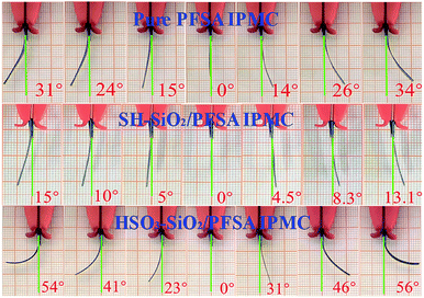
Actuations of IPMCs were captured and shown in Fig. 7. Clearly, all IPMCs from the pure PFSA, SH–SiO2/PFSA, and HSO3–SiO2/PFSA films generate stable electromechanical bending, and their maximum swing angles are 65, 28, and 110°, respectively. According to the electromechanical response mechanism, driven by the electric field, hydrated Li+ ions migrate from the anode to the cathode, thus forms a water concentration gradient, causing IPMC to bend towards the anode.1,49,50 Therefore, the amounts of hydrated Li+ ions and inner channels are critical to IPMC bending.17,49 Due to introduction of the hydrophilic sulfonic acid groups, the HSO3–SiO2/PFSA film possesses a higher IEC and a higher WU when compared to the control, those data potentially increase to 1.87 and 1.80 folds, respectively (Table 2). Thus the doping of HSO3–SiO2 nanocolloids benefits to improve IPMC actuation as discussed below. (1) because the polar sulfonic acid group takes part in the formation of inner channel, thus the hybrid film would possess enlarged and more interconnected inner channels.46 (2) Substantial Li+ ions are introduced into the hybrid film as counter cations to balance the sulfonic acid anions, thus provides enough movable hydrated cations to migrate. (3) Driven by the electric field, the hydrated cations (i.e., Li+) migrate from one end of sulfonic acid group to another end along inner channels, therefore a large number of sulfonic acid groups provide a large number of ion exchanging sites, supporting the fast migration of hydrated cations.51 Additionally, high WU of the matrix film also brings two evident benefits for IPMC as discussed below. (1) High WU makes the matrix film flexible, which benefits to generate larger deformation; (2) high WU benefits to maintain stable concentration of the hydrated cations, and subsequently stable actuation, because IPMC cannot work without electrolyte solution.52 Overall, increasing IEC and improving the hydrophilicity of the matrix film are effective strategies to enhance IPMC electromechanical deformation.Electromechanical performance analyses of IPMCs
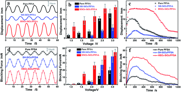
Displacement and force outputs are two important parameters for assessing IPMC electromechanical response.53 Typical displacement and force output curves are recorded in Fig. 8a and d. By using a sinusoid signal as the driving source, both displacement and force curves exhibit typical sinusoid characterization, showing a good correlation between the electromechanical behaviour and the driving electric field. Fig. 8b and e record the displacement and force evolution curves with increasing the driving voltage. Voltages of 1.0–3.0 V were used to drive IPMC actuators. Clearly, both displacement and force increase with increasing the driven voltage. Under the same actuation voltage of 2.5 V, three IPMC actuators from the control, SH–SiO2/PFSA, and HSO3–SiO2/PFSA matrix films exhibit maximum displacement outputs of 10.43, 4.08, 15.77 mm, and maximum force outputs of 12.03, 27.32, 40.03 mN, respectively (Table 3). Their total deflection angles including left and right swing angles are 65, 28, and 110°, respectively (Table 3). Collectively, IPMC of HSO3–SiO2/PFSA exhibits the strongest displacement and force outputs, resulting from the high IEC, WU, Li+ ion conductivity, and flexibility of the matrix film.| Sample | Max displacement at 2.5 V mm−1 | Stable working time at 2.5 V s−1 | Total deflection angle at 2.5 V °−1 | Max blocking force at 2.5 V mN−1 | Max displacement at 3.0 V mm−1 | Stable working time at 3.0 V s−1 | Total deflection angle at 3.0 V °−1 | Max blocking force at 3.0 V mN−1 |
|---|---|---|---|---|---|---|---|---|
| Pure PFSA | 10.43 | ∽130 | 65 | 12.03 | 13.16 | ∽110 | 86 | 19.74 |
| SH–SiO2/PFSA | 4.08 | ∽230 | 28 | 27.32 | 5.61 | ∽150 | 39 | 38.97 |
| HSO3–SiO2/PFSA | 15.77 | >580 | 110 | 40.03 | 16.43 | >240 | 112 | 44.87 |
Profiles of displacement and force outputs shown in Fig. 8c and f confirm the above results. Under the same actuation voltage of 2.5 V, all three displacement curves exhibit an initial rise followed by a relatively stable displacement output, corresponding to the stable working time for the actuator. This result might be explained by the fact that, all the inner channels are not completely interconnected and the hydrate Li ions migrate and gradually open the inner channels driven by electric field.34,35 Finally, the electromechanical response goes recession with the water loss (Fig. 8c). As the blocking force of IPMC originates from its deformation, force profiles shown in Fig. 8f correlate well with displacement profiles shown in Fig. 8c. Based on HSO3–SiO2/PFSA film with varying thicknesses of 0.34–0.41 mm, the detected forces of IPMCs increase from 26.31 mN to 44.45 mN, but the deflection angles decrease from 118° to 89° under 2.5 V driven voltage, showing a competitive correlation between force output and displacement output, where a thicker matrix film always leads to smaller deformation and larger blocking force.
Additional evidence shows improved working time performance of HSO3–SiO2/PFSA compared to control. With continuous actuation in air, IPMC actuators may lose almost all water and subsequently stop actuation.52 Under the driving voltage of 2.5 V, the HSO3–SiO2/PFSA based IPMC exhibits a stable bending time of more than 580 s, its force output also keeps stable for 440 s, both data are much better than other two IPMCs (Table 3). Collectively, the HSO3–SiO2 hybrid IPMC actuator exhibits better electromechanical properties compared to the pure PFSA film IPMC actuator: 1.51 folds in displacement output, 3.33 folds in force output, and 4.46 folds stable working time. Based on above results, we conclude that: introduction of sulfonic SiO2 nanocolloids can significantly enlarge the inner channels, increase the density of inner channels, and increase ion exchange rate, thus enhancing the IPMC's electromechanical properties.
Conclusions
Sulfonic SiO2 nanocolloids (HSO3–SiO2) were fabricated by initial hydrolysis of the commercial precursor of (3-mercaptopropyl)trimethoxysilane, thus forming thiol functionalized SiO2 nanocolloids (SH–SiO2), followed by oxidization of thiol group into sulfonic acid group. IR and high resolution XPS spectra monitored the total reaction courses, and demonstrated the successful preparation of the title nanocolloids. High resolution TEM observations revealed that, both SiO2 nanocolloids presented similar, amorphous capsule structure, their mean diameters were ∼14 nm for the HSO3–SiO2 nanocolloid, and ∼25 nm for the SH–SiO2 nanocolloid. Both SiO2 nanocolloids were used as additives to modify the PFSA film for fabricating IPMC-used matrix films. FESEM observations of hybrid films revealed that, the SH–SiO2 nanocolloids took evident phase separation in the cocrystallization course, and aggregated into huge, regular spherical particles with a mean diameter of ∼690 μm, which separately dispersed in the matrix film; while the HSO3–SiO2 nanocolloids were rather compatible with the PFSA, thus forming a very homogeneous copolymer. Other related physiochemical investigations by analytical tools revealed that, the HSO3–SiO2 hybrid IPMC actuator exhibits better electromechanical properties compared to the pure PFSA film IPMC actuator: 1.51 folds in displacement output, 3.33 folds in force output, and 4.46 folds stable working time. Such high-performance and cost-effective IPMC could be used as a valuable artificial muscle for flexible actuators or displacement/vibration sensors at low cost.Conflicts of interest
There are no conflicts to declare.Acknowledgements
This work was supported by Yangtze River Scholar Innovation Team Development Plan (IRT1187), National Natural Science Foundation in China (U1704149, U1704256, 81771988), Open Fund of Key Laboratory for Intelligent Nano Materials and Devices of the Ministry of Education (INMD-2019M04).Notes and references
- M. Shahinpoor and K. J. Kim, Smart Mater. Struct., 2001, 10, 819–833 CrossRef CAS.
- F. Invernizzi, S. Dulio, M. Patrini, G. Guizzetti and P. Mustarelli, Chem. Soc. Rev., 2016, 45, 5455–5473 RSC.
- Y. Shi and Z. Chen, J. Mater. Chem. C, 2018, 6, 11817–11834 RSC.
- D. Chen and Q. B. Pei, Chem. Rev., 2017, 117, 11239–11268 CrossRef CAS PubMed.
- T. Fukushima, K. Asaka, A. Kosaka and T. Aida, Angew. Chem., Int. Ed., 2005, 44, 2410–2413 CrossRef CAS PubMed.
- G. Wu, Y. Hu, Y. Liu, J. Zhao, X. Chen, V. Whoehling, C. Plesse, G. T. Nguyen, F. Vidal and W. Chen, Nat. Commun., 2015, 6, 7258 CrossRef CAS PubMed.
- M. Kotal, J. Kim, K. J. Kim and I. K. Oh, Adv. Mater., 2016, 28, 1610–1615 CrossRef CAS PubMed.
- Z. Chen, K. Y. Kwon and X. B. Tan, Sens. Actuators, A, 2008, 144, 231–241 CrossRef CAS.
- S. Lee, H. C. Park and K. J. Kim, Smart Mater. Struct., 2005, 14, 1363–1368 CrossRef CAS.
- C. Lu, L. Zhao, Y. Hu and W. Chen, Chem. Commun., 2018, 54, 8733–8736 RSC.
- H. R. Cheong, N. T. Nguyen, M. K. Khaw, B. Y. Teoh and P. S. Chee, Lab Chip, 2018, 18, 3207–3215 RSC.
- M. Shahinpoor and K. J. Kim, Smart Mater. Struct., 2004, 14, 197–214 CrossRef.
- V. K. Nguyen and Y. Yoo, Sens. Actuators, B, 2007, 123, 183–190 CrossRef CAS.
- V. K. Nguyen, J. W. Lee and Y. Yoo, Sens. Actuators, B, 2007, 120, 529–537 CrossRef CAS.
- J. D. Nam, H. R. Choi, Y. S. Tak and K. J. Kim, Sens. Actuators, A, 2003, 105, 83–90 CrossRef CAS.
- J. W. Lee, S. Yu, S. M. Hong and C. M. Koo, J. Mater. Chem. C, 2013, 1, 3784–3793 RSC.
- D. J. Guo, S. J. Fu, W. Tan and Z. D. Dai, J. Mater. Chem., 2010, 20, 10159–10168 RSC.
- L. Naji, J. A. Chudek, E. W. Abel and R. T. Baker, J. Mater. Chem. B, 2013, 1, 2502–2514 RSC.
- K. A. Mauritz and R. B. Moore, Chem. Rev., 2004, 104, 4535–4585 CrossRef CAS PubMed.
- D. J. Gargas, D. A. Bussian and S. K. Buratto, Nano Lett., 2005, 5, 2184–2187 CrossRef CAS PubMed.
- W. Y. Hsu and T. D. Gierke, J. Membr. Sci., 1983, 13, 307–326 CrossRef CAS.
- P. H. Vargantwar, M. C. Brannock, S. D. Smith and R. J. Spontak, J. Mater. Chem., 2012, 22, 25262–25271 RSC.
- M. Luqman, J. W. Lee, K. K. Moon and Y. T. Yoo, J. Ind. Eng. Chem., 2011, 17, 49–55 CrossRef CAS.
- M. J. Han, J. H. Park, J. Y. Lee and J. Y. Jho, Macromol. Rapid Commun., 2006, 27, 219–222 CrossRef CAS.
- A. Khan, R. K. Jain, B. Ghosh, I. Inamuddin and A. M. Asiri, RSC Adv., 2018, 8, 25423–25435 RSC.
- L. Naji, M. Safari and S. Moaven, Carbon, 2016, 100, 243–257 CrossRef CAS.
- J. Ru, Z. C. Zhu, Y. J. Wang, H. L. Chen and D. C. Li, RSC Adv., 2018, 8, 3090–3094 RSC.
- J. H. Jeon, S. P. Kang, S. Lee and I. K. Oh, Sens. Actuators, B, 2009, 143, 357–364 CrossRef.
- Y. J. Tang, C. Chen, Y. S. Ye, Z. G. Xue, X. P. Zhou and X. L. Xie, Polym. Chem., 2014, 5, 6097–6107 RSC.
- Y. J. Tang, Z. G. Xue, X. P. Zhou, X. L. Xie and C. Y. Tang, Sens. Actuators, B, 2014, 202, 1164–1174 CrossRef CAS.
- C. H. Rhee, H. K. Kim, H. Chang and J. S. Lee, Chem. Mater., 2005, 17, 1691–1697 CrossRef CAS.
- C. C. Ke, X. J. Li, Q. Shen, S. G. Qu, Z. G. Shao and B. L. Yi, Int. J. Hydrogen Energy, 2011, 36, 3606–3613 CrossRef CAS.
- S. Z. Ren, G. Q. Sun, C. N. Li, Z. X. Liang, Z. M. Wu, W. Jin, X. Qin and X. F. Yang, J. Membr. Sci., 2006, 282, 450–455 CrossRef CAS.
- K. J. Kim and M. Shahinpoor, Smart Mater. Struct., 2003, 12, 65–79 CrossRef CAS.
- S. Shylesh, P. P. Samuel, C. Srilakshmi, R. Parischa and A. P. Singh, J. Mol. Catal. A: Chem., 2007, 274, 153–158 CrossRef CAS.
- R. Lenigk, M. Carles, N. Y. Ip and N. J. Sucher, Langmuir, 2001, 17, 2497–2501 CrossRef CAS.
- Z. C. Liu, Q. G. He, P. Hou, P. F. Xiao, N. Y. He and Z. H. Lu, Colloids Surf., A, 2005, 257, 283–286 CrossRef.
- D. J. Guo, S. J. Xiao, B. Xia, S. Wei, J. Pei, Y. Pan, X. Z. You, Z. Z. Gu and Z. H. Lu, J. Phys. Chem. B, 2005, 109, 20620–20628 CrossRef CAS PubMed.
- D. J. Guo, H. T. Ding, H. J. Wei, Q. S. He, M. Yu and Z. D. Dai, Sci. China, Ser. E: Technol. Sci., 2009, 52, 3061–3070 CrossRef CAS.
- D. J. Guo, R. Liu, Y. Cheng, H. Zhang, L. M. Zhou, S. M. Fang, W. H. Elliott and W. Tan, ACS Appl. Mater. Interfaces, 2015, 7, 5480–5487 CrossRef CAS PubMed.
- D. J. Guo, Y. B. Han, J. J. Huang, E. C. Meng, L. Ma, H. Zhang and Y. H. Ding, ACS Appl. Mater. Interfaces, 2019, 11, 2386–2397 CrossRef CAS PubMed.
- V. Panwar, K. Cha, J. O. Park and S. Park, Sens. Actuators, B, 2012, 161, 460–470 CrossRef CAS.
- M. Rajagopalan, J. H. Jeon and I. K. Oh, Sens. Actuators, B, 2010, 151, 198–204 CrossRef CAS.
- D. J. Guo, R. Liu, Y. K. Li, W. H. Elliott, J. P. Du, H. Zhang, Y. H. Ding, W. Tan and S. M. Fang, Sens. Actuators, B, 2018, 255, 791–799 CrossRef CAS.
- C. Oh, S. Kim, H. Kim, G. Park, J. Kim, J. Ryu, P. Li, S. Lee, K. No and S. Hong, RSC Adv., 2019, 9, 14621–14626 RSC.
- Y. Liu, M. Ghaffari, R. Zhao, J. H. Lin, M. Lin and Q. M. Zhang, Macromolecules, 2012, 45, 5128–5133 CrossRef CAS.
- A. Khaldi, J. A. Elliott and S. K. Smoukov, J. Mater. Chem. C, 2014, 2, 8029–8034 RSC.
- J. W. Lee, S. M. Hong, J. Kim and C. M. Koo, Sens. Actuators, B, 2012, 162, 369–376 CrossRef CAS.
- L. Naji, J. A. Chudek, E. W. Abel and R. T. Baker, J. Mater. Chem. B, 2013, 1, 2502–2514 RSC.
- J. K. Park, P. J. Jones, C. Sahagun, K. A. Page, D. S. Hussey, D. L. Jacobson, S. E. Morgan and R. B. Moore, Soft Matter, 2010, 6, 1444–1452 RSC.
- Q. Liu, L. Q. Liu, K. Xie, Y. N. Meng, H. P. Wu, G. R. Wang, Z. H. Dai, Z. X. Wei and Z. Zhang, J. Mater. Chem. A, 2015, 3, 8380–8388 RSC.
- J. Li, K. G. Wilmsmeyer, J. B. Hou and L. A. Madsen, Soft Matter, 2009, 5, 2596–2602 CAS.
- O. Kim, S. J. Kim and M. J. Park, Chem. Commun., 2018, 54, 4895–4904 RSC.
| This journal is © The Royal Society of Chemistry 2019 |

