
 Open Access Article
 This Open Access Article is licensed under a Creative Commons Attribution-Non Commercial 3.0 Unported Licence
A 2D metal–organic framework/reduced graphene oxide heterostructure for supercapacitor application
Lemu Girma Beka,
Xiangrui Bu,
Xin Li,
Xiaoli Wang,
Chuanyu Han and
Weihua Liu *
*
School of Microelectronics, School of Electronic and Information Engineering, Xi'an Jiaotong University, Xi'an, 710049, P. R. China. E-mail: lwhua@mail.xjtu.edu.cn
First published on 7th November 2019
Abstract
Metal organic frameworks (MOFs) with two dimensional (2D) nanosheets have attracted special attention for supercapacitor application due to their exceptional large surface area and high surface-to-volume atom ratios. However, their electrochemical performance is greatly hindered by their poor electrical conductivity. Herein, we report a 2D nanosheet nickel cobalt based MOF (NiCo-MOF)/reduced graphene oxide heterostructure as an electrode material for supercapacitors. The NiCo-MOF 2D nanosheets are in situ grown on rGO surfaces by simple room temperature precipitation. In such hybrid structure the MOF ultrathin nanosheets provide large surface area with abundant channels for fast mass transport of ions while the rGO conductive and physical support provides rapid electron transport. Thus, using the synergistic advantage of rGO and NiCo-MOF nanosheets an excellent specific capacitance of 1553 F g−1 at a current density of 1 A g−1 is obtained. Additionally, the as synthesized hybrid material showed excellent cycling capacity of 83.6% after 5000 cycles of charge–discharge. Interestingly, the assembled asymmetric device showed an excellent energy density of 44 W h kg−1 at a power density of 3168 W kg−1. The electrochemical performance obtained in this report illustrates hybridization of MOF nanosheets with carbon materials is promising for next generation supercapacitors.
1. Introduction
Research and development of energy-storage devices has been attracting increasing interest due to the worldwide environmental issues and the high demand of portable electronic devices in the upcoming internet of things. Among the different energy storage technologies, supercapacitors have attracted the interest of many researchers because of their high power density1 and long cycle life.2,3 Thus, supercapacitor technology has been experiencing an impressive performance improvement by using the concept of nanomaterial engineering. However, advanced electrode materials with fully accessible surface area, fast transport of ions and electrons, and stable electrode/electrolyte interface are still highly in demand. Materials like carbon, conducting polymers, transition metals and MOFs have been under study for supercapacitor applications.4–14 Among these MOF are materials made of transition metals and organic linkers and emerged as a new class of supercapacitor electrode materials with tuneable porosity, large specific surface area and excellent physical and chemical properties.15 The combined high surface area and redox-active metal centres makes MOFs promising material for energy storage application.16,17 For example, Yaghi et al.18 has carried out a series of experiments on 23 different MOFs and demonstrated as MOFs are potential electrode materials for supercapacitor application. Nickel based metal–organic framework are reported as electrode material with high specific capacitance of 726 F g−1 and good electrochemical stability of 94.6% after 1000 cycles of charge discharge.19 Even though MOF based material has showed good capacitive properties, their poor electrical conductivity and poor cycling stability limited their practical application.16,17,20 So, structural/morphological engineering of MOF materials and hybridizing with conductive and stable materials is becoming interesting research area to solve such challenges.7,21–24 Among these hybridizing with graphene based materials can give improved performance because of their large internal surface area for anchoring MOFs materials and excellent electrical conductivity for electron transport.25–31 For example, Yaghi et al.18 showed as hybridizing MOFs with graphene has potential to enhance electrode materials for supercapacitor application. Zhou et al.32 reported Ni-MOFs@GO as pseudocapacitors materials with a capacitance of 1457.7 F g−1 at a current density of 1 A g−1. Besides hybridizing with carbon materials, the achievable maximum specific capacitance of MOFs can also be enhanced by designing advanced structures. Structure/morphology unquestionably play key role on electrochemical performance of MOF based electrode materials. Thus, exploring advanced MOF architectures self-supported in graphene matrix are highly desirable to enhance both rate and cycling stability issues. Among these 2D ultrathin MOF nanosheets integrated to conductive physical support are attracting increasing research attention due to their exceptional properties related to their ultrathin thickness such as large surface area and high surface-to-volume atom ratios.33–35Herein, we report 2D NiCo-MOF ultrathin nanosheets/rGO hybrid electrode materials for supercapacitor application. The NiCo-MOF nanosheets/rGO hybrid material is made by facile room temperature precipitation. In this heterostructure the rGO serve as ionic and electronic conductive pathway while NiCo-MOF nanosheets with highly exposed active sites can serve as excellent pseudocapacitive material. Moreover, in this experiment we tuned the ratio of rGO and we obtained optimal electrochemical performance. The best optimal electrode material where the rGO network serves as continuous conductive networks to ensure fast electron and ionic transport and the ultrathin nanosheets with open structure promote the adsorption and diffusion of ions resulted in high pseudocapacitive material and provide high charge storage capacity. The highest specific capacitance obtained is 1553 F g−1 at current density of 1 A g−1. Moreover the as synthesized material showed excellent cycling stability of 83.6% after 5000 cycles of charge discharge. Thus, 2D MOF nanosheets/rGO heterostructure is a promising candidate electrode material for future energy storage application.
2. Experimental
2.1 Preparation of rGO
Pours rGO is prepared by using sulphur as template precursor. In detail, 0.05 g of GO is added to 25 ml of DI water and sonicated for 3 hours. Next, a solution containing 3 ml of 1 M Na2S2O3·5H2O is added into the pre-sonicated rGO and mixed by magnetic stirring while adding 3 ml of 2 M HCl drop wise during stirring process. Then, the as prepared homogenous solution is transferred to a 50 ml Teflon-lined stainless steel autoclave and hydrothermally treated at a temperature of 180 °C for 6 hours and rGO/sulphur composite is obtained. Then, after washing in DI water it is dried at a temperature of 60 °C for 24 hours. Finally, the as prepared rGO/sulphur is annealed at 500 °C at heating rate of 0.5 deg sec−1 in the presence of argon gas at flew rate of 78 sccm and after 5 hours pours 3D rGO is obtained.2.2 Preparation of 2D NiCo-MOF nanosheets/rGO heterostructure
NiCo-MOF/rGO hybrid material is prepared by a one step room temperature precipitation process. In detail, a homogenous solution containing 0.4365 g of cobalt(II) nitrate hexahydrate, 0.873 g of nickel(II) nitrate hexahydrate, 0.48875 g of 2 methylimidazole, 50 ml of methanol and the rGO prepared in Section 2.1 is added according to the data given in Table 1 and mixed by string process. Then, the solution is kept at room temperature for 24 hours. Finally, after centrifugation and washing process followed by drying process 2D NiCo-MOF/rGO is obtained as final product.| Sample name | rGO (mg) | Co(NO3)2·6H2O (g) | Ni(NO3)2·6H2O (g) | 2 Methylimidazole (g) | Methanol (ml) |
|---|---|---|---|---|---|
| NiCo-MOF/rGO-0 | 0 | 0.4365 | 0.873 | 0.48875 | 50 |
| NiCo-MOF/rGO-1 | 5.0 | 0.4365 | 0.873 | 0.48875 | 50 |
| NiCo-MOF/rGO-2 | 10 | 0.4365 | 0.873 | 0.48875 | 50 |
| NiCo-MOF/rGO-3 | 20 | 0.4365 | 0.873 | 0.48875 | 50 |
2.3 Structural characterization methods
To study the structure and composition of as synthesized electrode material different characterization techniques are used. The key structural characterization device used are Field Emission Scanning Electron Microscopy (FE-SEM, Gemini SEM 500, Zeiss, Germany), Field Emission Transmission Electron Microscope (FE-TEM), X-ray diffraction (XRD) spectra (Bruker D8 ADVANCE), and X-ray Photoelectron Spectroscopy (XPS, Thermo Fisher ESCALAB Xi+). FE-SEM and FE-TEM were used to study the topography/morphology of the as synthesized electrode materials. The XPS analysis was used to understand the surface chemical states and bonding issues in the hybrid materials. XRD test was used to study the crystal structure of the as synthesized electrode materials.2.4 Electrochemical characterization methods
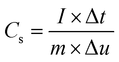
Multi channel electrochemical workstation (CS 2350 Corrtest, Wuhan, China) was used to study electrochemical performance of as synthesized materials. In all tests we used three electrode configurations mode where the active material was used as working electrode while Hg/HgO and platinum sheets were used as reference and counter electrodes, respectively. The electrochemical tests conducted were cyclic voltammetry (CV) test, galvanic charge/discharge (GCD) test and electrochemical impedance spectroscopy (EIS) tests. The specific capacitance is calculated from the GCD plots. The average mass specific capacitance values in three electrodes configuration can be calculated from GCD curves, using eqn (1):36,37
 | (1) |
 | (2) |
 | (3) |
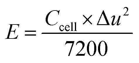
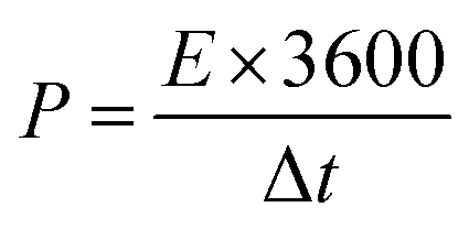
Assessments of energy and power densities are other key parameters to evaluate the practical performance of a supercapacitor cell. The energy density (W h kg−1) is the capacity to perform work, whereas the power density (W kg−1) is the rate at which the stored energy can be supplied. Thus, the relations given in eqn (3) and (4) were used to calculate energy and power densities, respectively.36
 | (4) |
 | (5) |
3. Results and discussion
3.1 Structural characterization methods
The synthesis strategy of NiCo-MOF/rGO is illustrated in Fig. 1. Prior to NiCo-MOF/rGO preparation rGO sheet is prepared using sulphur as template material. In detail sulphur nanoparticles are warped to rGO sheets by self assembly process using hydrothermal process, and next the sulphur nanoparticles are melted out using annealing process to form 3D porous rGO networks. Once 3D rGO is obtained, a room temperature precipitation is conducted to obtain NiCo-MOF/rGO as a final product (illustrated in Fig. 1). To optimize the performance of NiCo-MOF/rGO we conducted a series of experiments using different concentration of rGO precursors. In this work we varied the amount of rGO concentration keeping the amount of MOF concentration constant as shown in Table 1. The different samples prepared using different concentration ratios of precursor are named as NiCo-MOF/rGO-0, NiCo-MOF/rGO-1, NiCo-MOF/rGO-2 and NiCo-MOF/rGO-3 as given in Table 1. | ||
| Fig. 1 Schematic illustration of NiCo-MOF nanosheet/rGO growth process. | ||
The structures of as synthesized hybrid materials were characterized using different structural characterization techniques. Fig. 2 illustrates the typical FE-SEM image of as synthesized different samples at different magnifications. Fig. 2a to c shows FE-SEM image of NiCo-MOF/rGO-0 (a pristine MOF material prepared without rGO). It shows uniform density of MOF nanosheets forming flower like framework. Fig. 2d to f shows SEM image of NiCo-MOF/rGO-1 hybrid material. Compared to pristine MOF shown in Fig. 2a to c, sample NiCo-MOF/rGO-1 used rGO as a physical support background and high density of MOF nanosheets are grown on the rGO sheets. Fig. 2g to i shows NiCo-MOF/rGO-2 sample. Fig. 2j to l shows SEM image of NiCo-MOF/rGO-3 hybrid material. In NiCo-MOF/rGO-3 hybrid material relatively high density of rGO is observed compared to other samples since high concentration of rGO is used. The SEM images revealed as uniform density of MOF nanosheets having honeycomb structure is uniformly grown on the surface of rGO sheets. In this hybrid material the MOF nanosheets size is not big as in other samples. In general from Fig. 2 we can learn as density and size of MOF grown on rGO sheet can be controlled by varying the ratio of rGO to MOF precursor. Additionally we can learn as rGO is used as interconnected network background for 2D NiCo-MOF nanosheets.
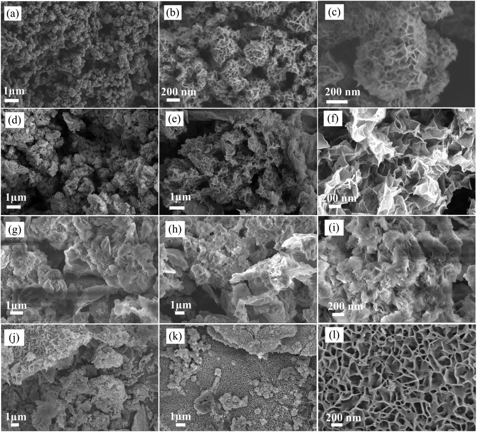 | ||
| Fig. 2 FE-SEM image of different NiCo-MOF/rGO samples prepared by varying rGO concentration at different magnification (a) to (c) NiCo-MOF/rGO-0, (d) to (f) NiCo-MOF/rGO-1, (g) to (i) NiCo-MOF/rGO-2 and (j) to (l) NiCo-MOF/rGO-3. | ||
The growth mechanism of as synthesized samples can be proposed as follows. During porous rGO preparation step the HCl which was used to generate free sulphur was simultaneously used to functionalize the rGO sheets. Then when MOF precursors and rGO are evenly dispersed in the solution under strong string process the functionalized and negatively charged sites of rGO can serve as electrostatic attraction sites and the positively charged metal ions are attracted to these sites and nucleation of MOF precursor starts.35 It is reasonable to assume as the density of negatively charged sites depends on rGO concentration ratio in the solution and can be used to tune the nucleation of MOF precursors. Thus, at low concentration of rGO there is limited amount of negatively charged attraction sites and few MOF precursors participated to form nucleation centre and most MOF precursors are used during the growth process and large nanosheets are obtained. On the other hand if rGO ratio is highly increased most of MOF precursors are absorbed on the surface to form nucleation (during nucleation stage) and the amount of MOF precursor participated in growth process limited and the size of nanosheets are becomes shorter compared with the high concentration of MOF precursors to rGO ratio samples. Thus the balance between nucleation and growth of MOF precursor on the rGO sheet enable to synthesize ultrathin 2D nanosheets of MOF on rGO sheets. This strategy is feasible way to synthesize controlled-size NiCo-MOF nanosheets on rGO.35
To study about structure and morphology of as synthesized hybrid materials representative TEM image of NiCo-MOF/rGO-3 hybrid material at different magnification is given in Fig. 3. The TEM images clearly demonstrates as ultrathin MOF nanosheets are grown on rGO sheets which is in agreement with SEM images given in Fig. 2. It is remarkable that the presence of wrinkles and folds reveals its good flexibility.
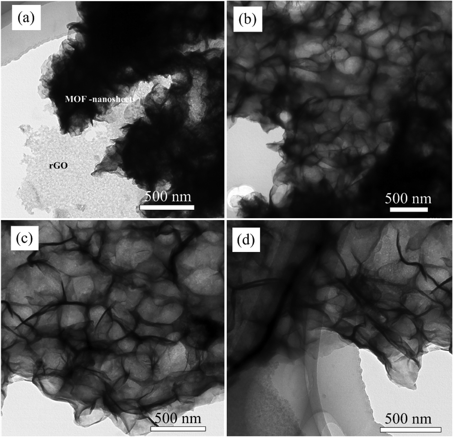 | ||
| Fig. 3 (a) to (d) TEM image of NiCo-MOF nanosheets/rGO at different magnification. | ||
In order to study the elemental composition of NiCo-MOF/rGO-3 hybrid structure elemental mapping analysis is conducted. To clearly show the difference between rGO and NiCo-MOF/rGO we presented the EDAX mapping of both materials as shown in Fig. 4. Clearly, the pristine rGO (Fig. 4b) shows almost one color along the whole surface dominated by carbon element. For more information elements count and wt% ratio of Fig. 4b is shown in Fig. 4c and inset of Fig. 4c. The sulphur part is originated from template sulphur we used to prepare our porous rGO. Thus there is little sulphur doped into our rGO sheets.39 The EDAX of NiCo-MOF/rGO is shown in Fig. 4e, clearly it shows different colours illustrating existence of different elements which is by far different from the pristine rGO mapping image. In NiCo-MOF/rGO EDAX mapping (Fig. 4e) the distribution of colour density varies depending on the elements distribution. For example to the right of dot line marked area of Fig. 4d the backbone rGO sheets can be clearly observed. Correspondingly, on the EDAX image shown in Fig. 4e high density of carbon (red colour) is observed on this section. For more insight about the share of elements in the hybrid materials elemental wt% ratio analysis is in inset Fig. 4f.
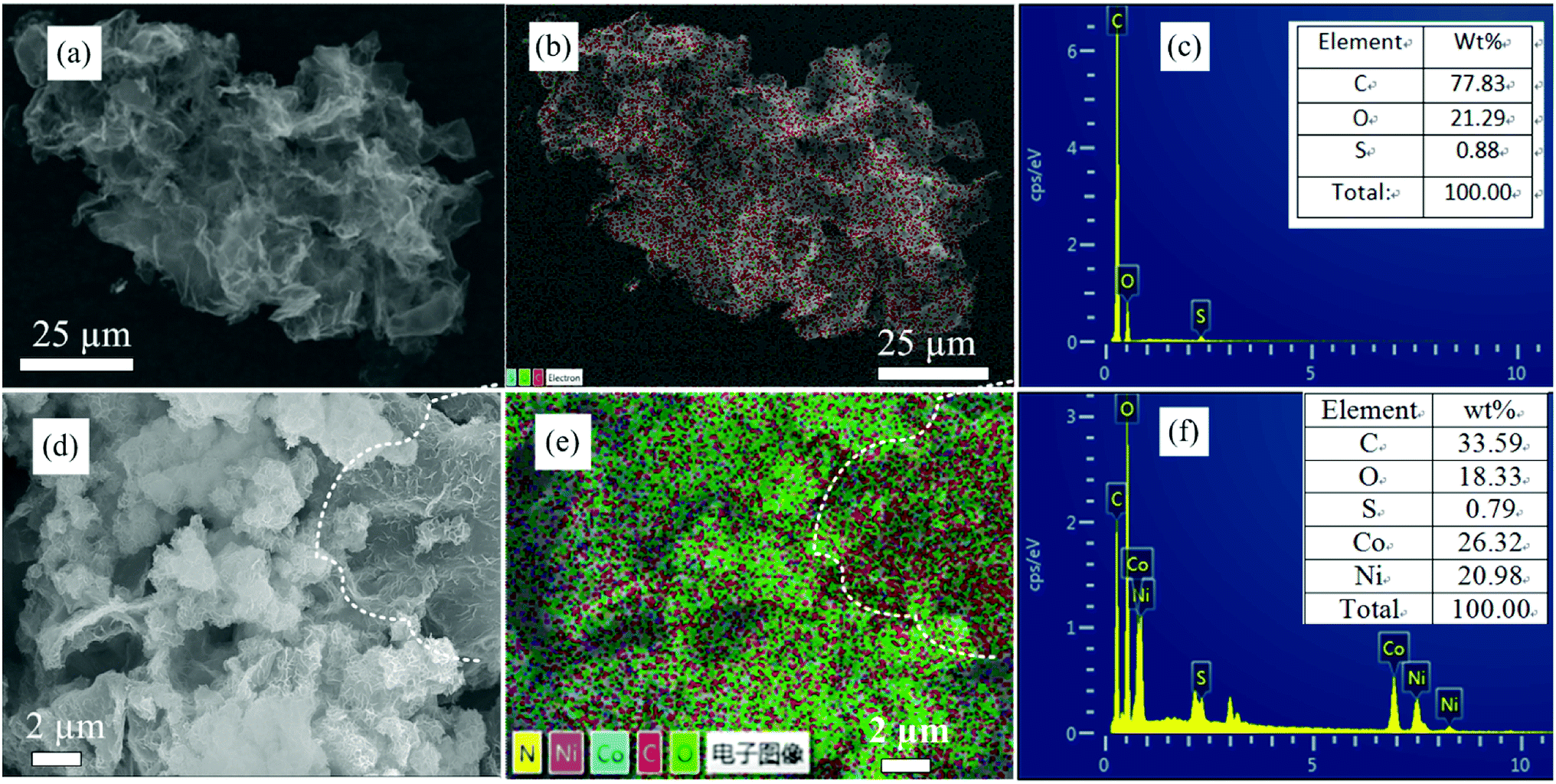 | ||
| Fig. 4 (a) SEM image of pristine rGO where EDAX mapping and counts ratio taken, (b) elemental mapping of pristine rGO, (c) elemental count ratios in pristine rGO, (d) SEM image of NiCo-MOF/rGO where EDAX mapping and counts ratio taken, (e) elemental mapping of NiCo-MOF/rGO, (f) elemental count ratios in NiCo-MOF/rGO. | ||
To know the effect of such rGO ratios on the surface area of the as synthesis hybrid materials BET surface area of our samples were analyzed using nitrogen adsorption–desorption isotherms (Fig. 5a). The isotherms plots of the samples showed an abrupt increase at low relative pressure (P/P0 < 0.05) indicating existence of microporous which is in agreement with type-I isotherm N2 adsorption–desorption isotherm.40 Relatively, NiCo-MOF/rGO-0 showed high uptake without hysteresis loop indicating the highly microporous nature of the sample. However, as the amount of rGO in the sample is getting increased the abrupt increase in N2 adsorption–desorption is getting decreased implying reduction of microspores in the hybrid material. On the other hand as rGO concentration is getting increased at relatively high pressure (P/P0 > 0.8) hysteresis loop is getting increased and increased indicating increase of mesopores in the hybrid material.41 Thus, this finding illustrates as rGO is used as spacer between the NiCo-MOF sheets and leads to formation of mesopores compared to the high density micropores observed in pristine materials. The obtained BET surface area of samples prepared without rGO is about 1256 m2 g−1. While for samples prepared with rGO the BET surface area are 987, 792, and 580 m2 g−1, respectively for NiCo-MOF/rGO-1, NiCo-MOF/rGO-2 and NiCo-MOF/rGO-3. The decrease in BET surface area in relation to rGO concentration is related to the formation of more mesopores and macropores as the concentration of rGO increased which can be evidenced from the hysteresis loops in the region of P/P0 > 0.8. In deed the important pore size for electrolyte transportation is mesopores. Thus, samples with optimal mesopores size are highly interesting by providing sufficient electrolyte ions transportation path in to active material during electrochemical charge–discharge processes.42
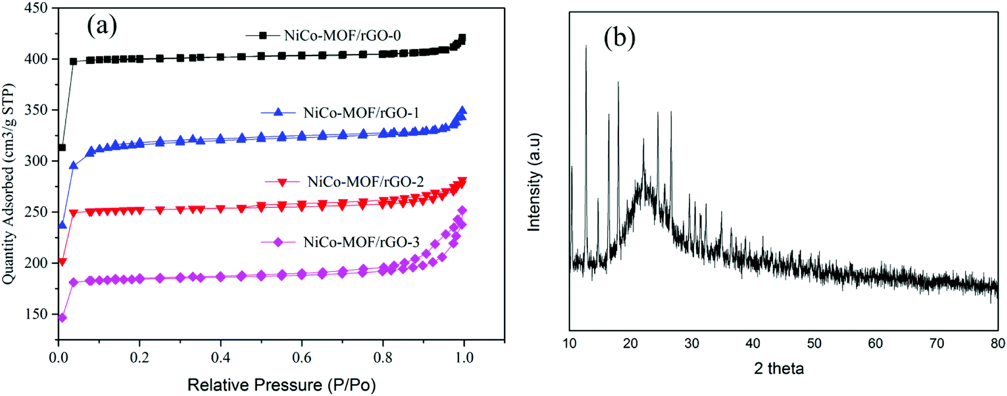 | ||
| Fig. 5 (a) Nitrogen adsorption–desorption isotherm NiCo-MOF/rGO at different ratio of rGO and (b) XRD of NiCo-MOF/rGO-2. | ||
XRD test was conducted to study about the crystal structure of as synthesized MOF/rGO. Fig. 5b shows XRD test of NiCo-MOF/rGO-2 hybrid material. The broad peak around 25° belongs to the rGO sheets which can be indexed to the crystal plan of 002 of graphene. The other sharp peaks at 10.4°, 12.7°, 14.8°, 16.5°, 18.0°, 22.1°, 24.5°, 25.5°, 26.7°, 29.5°, 30.6°, 31.6°and 32.5° and 36.9 belongs to NiCo-MOF XRD peaks. These peaks can be indexed to (002), (112), (022), (013), (222), (114), (233), (224), (134), (044), (334), (244) and (235) crystal structure of ZIF based materials which is almost in agreement with the previously reported NiCo-based MOFs.30,43–47
XPS test was conducted to analyze the surface chemical states and bonding of the samples. Fig. 6a illustrates the survey of different elements. Fig. 6b illustrates Ni 2p spectra; it shows binding energies around 855 and 873 eV which can be assigned to Ni 2p3/2 and Ni 2p1/2.48 For more information the detail deconvolution peaks of Ni 2p3/2 and Ni 2p1/2 are shown in Fig. 6b illustrating co-existence of Ni2+ and Ni3+. Fig. 6c illustrates Co 2p spectra; the binding energies around 780 and 795 eV show Co 2p3/2 and Co 2p1/2, respectively.48 The detail deconvolution peaks in Co 2p3/2 and Co 2p1/2 are shown in Fig. 6c illustrating the coexistence of Co2+ and Co3+. Fig. 6d illustrates C sp2 spectrum. Obviously, it shows strong peak around 284 eV confirming the existence of graphene in the composite and the other two peaks represented existence of O–C and C![[double bond, length as m-dash]](https://www.rsc.org/images/entities/char_e001.gif) O bonding.49,50 The N 1S spectrum is shown in Fig. 6e illustrates as the final hybrid structure is doped with nitrogen which may contribute better electrochemical activity.51 The peaks in N 1s are deconvoluted in to the following bonding, pyridinic bonding, nitrogen metal bonding, pyrrollic bonding and graphitic bonding.52 Fig. 6f represents XPS spectrum of oxygen which is in agreement with reported literature values. The Gaussian deconvolution of O 1s spectrum gives three kinds of oxygen in the hybrid material, namely metal–oxygen bond (fitting peak at 529.6 eV), oxygen at defect sites with weak oxygen coordination in materials (around 530.4 eV) and oxygen contributed due to physically and chemically bonded water on or near the surface (around 531.5 eV).46 The overall XPS spectra in Fig. 6 show as surface of the as synthesized hybrid material is made of carbon, cobalt, nickel, nitrogen and oxygen.
O bonding.49,50 The N 1S spectrum is shown in Fig. 6e illustrates as the final hybrid structure is doped with nitrogen which may contribute better electrochemical activity.51 The peaks in N 1s are deconvoluted in to the following bonding, pyridinic bonding, nitrogen metal bonding, pyrrollic bonding and graphitic bonding.52 Fig. 6f represents XPS spectrum of oxygen which is in agreement with reported literature values. The Gaussian deconvolution of O 1s spectrum gives three kinds of oxygen in the hybrid material, namely metal–oxygen bond (fitting peak at 529.6 eV), oxygen at defect sites with weak oxygen coordination in materials (around 530.4 eV) and oxygen contributed due to physically and chemically bonded water on or near the surface (around 531.5 eV).46 The overall XPS spectra in Fig. 6 show as surface of the as synthesized hybrid material is made of carbon, cobalt, nickel, nitrogen and oxygen.
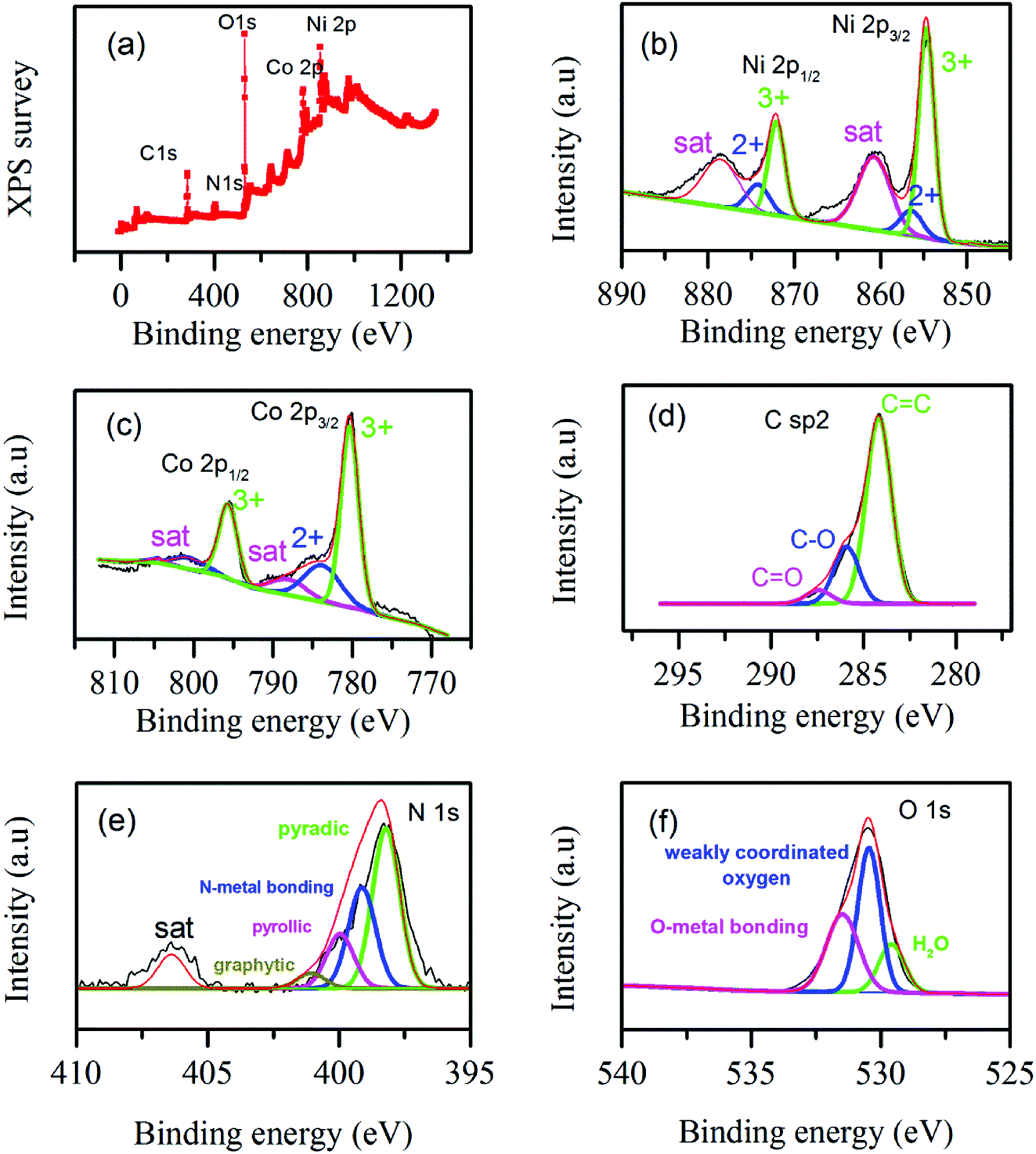 | ||
| Fig. 6 XPS spectra of elements in NiCo-MOF/rGO (a) elemental survey, (b) Ni 2p spectra, (c) Co 2p spectra, (d) C sp2 spectra, (e) N 1s spectra and (f) O 1s spectra. | ||
3.2 Electrochemical characterization
Comparative electrochemical test was conducted to study relative electrochemical characteristics of each samples. Fig. 7 shows typical comparative electrochemical characteristics test results of as synthesiszed different materials. Fig. 7a shows the relative CV test results of the different samples (NiCo-MOF/rGO-0, NiCo-MOF/rGO-1, NiCo-MOF/rGO-2 and NiCo-MOF/rGO-3). All samples showed a pair of redox peaks illustrating pseudocapacitive property of as synthesiszed materials originated from metal redox centers. The redox peaks originated during state transition of Co2+ to Co3+ and Ni2+/Ni3+ while the reduction peaks corresponds to reduction of Co4+ to Co3+ to Co2+ and Ni3+ to Ni2+.53 Thus, the multiple oxidation states of both materials increase the overall reduction and oxidation peak current densities. The increase of the redox peaks increase the enclosed area of CV loop and leads to increase in pseudocapacitive property of as synthesized material.54 The CV comparission result reavels as samples' CV area increases as the amount of rGO precursor in the sample increased initially (NiCo-MOF/rGO-0 < NiCo-MOF/rGO-1 < NiCo-MOF/rGO-2) and later decrease as rGO is further increased (NiCo-MOF/rGO-3 < NiCo-MOF/rGO-2).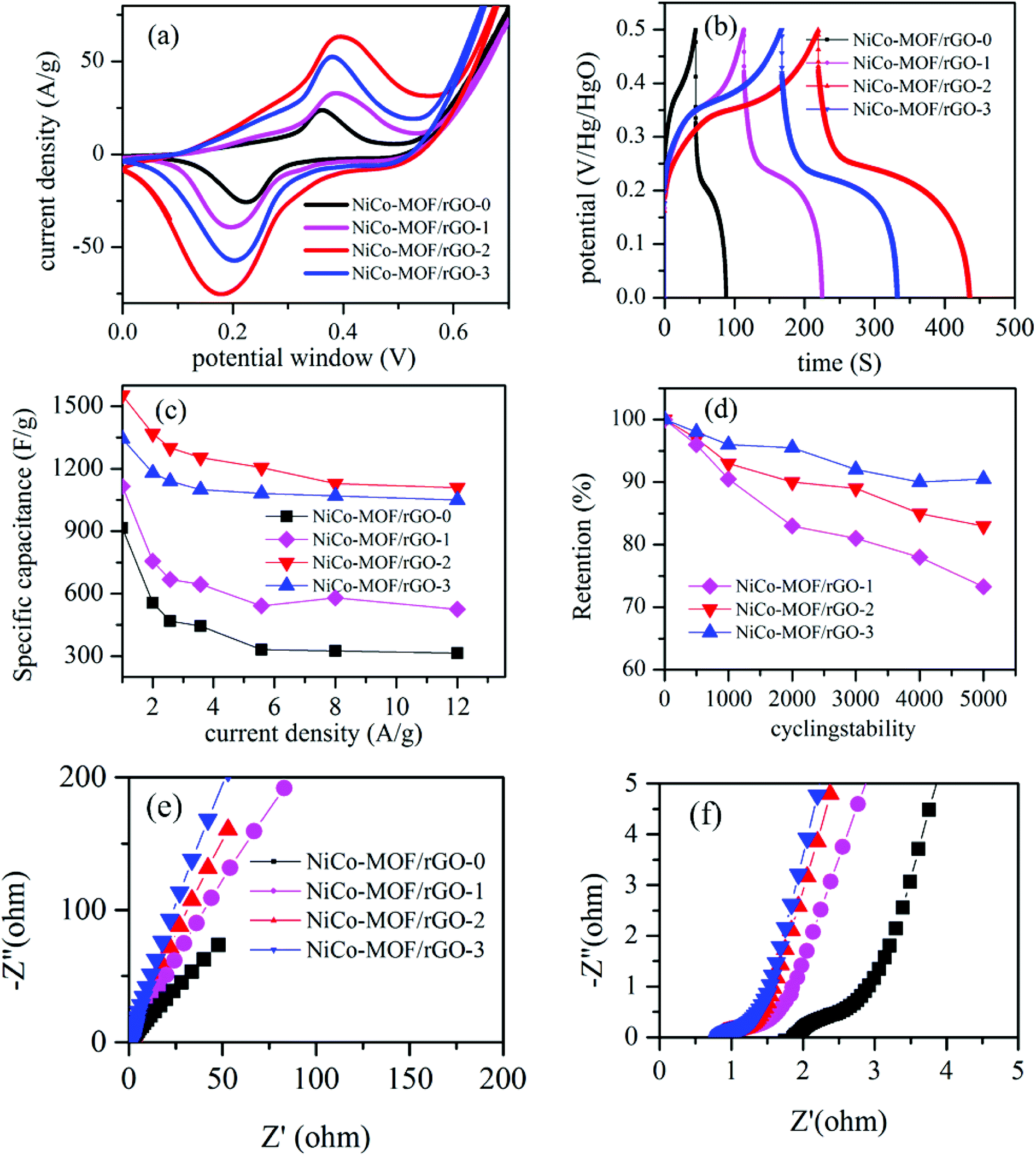 | ||
| Fig. 7 Electrochemical test characters (a) relative CV plots at scan rate of 1 mV s−1, (b) relative GCD plots at 4 mA g−1, (c) relative specific capacitance as a function of current density, (d) cycling stability test, (e) and (f) EIS plots at low and high frequency regions, respectively. | ||
Fig. 7b demonstrates comparative GCD plots of the as synthesiszed samples. In Fig. 7b, it is found that the GCD curves in all samples have two steps of discharges: initially the potential drops rapidly and latter it discharges slowly. The reason for this phenomenon is that during the initial discharge steps the active material is in the electrochemical inactive state and the electrode capacitance was primarily contributed by the electric double layer or surface charge storages. However, when the potential is reached a certain level the active materials is get activated and the device start to show pseudocapacitive property.55 Thus, a voltage plateaus in discharge curve is observed and these plateaus match with the redox peaks observed in the CV curves. This phenomenon indicates that the samples show an electric double layer capacitors property for short time at initial of discharging and exhibit pseudocapacitance behaviour after activation. All the GCD plots showed clear nonlinear plots illustrating pseudocapacitive property in all materials. The respective GCD area can give information about the relative specific capacitance performance of as synthesiszed samples. The GCD plot areas increase as rGO concentration is increased initially and decrease later as rGO precursor is further increased, which is in agreement with the CV area. To know more about specific capacitance at different current densities, the specific capacitance of all samples are calculated from their respective GCD graphs using eqn (1). The obtained maximum specific capacitance are 968, 1100, 1553 and 1451 F g−1 at current density of 1 A g−1, respectively for NiCo-MOF/rGO-0, NiCo-MOF/rGO-1, NiCo-MOF/rGO-2 and NiCo-MOF/rGO-3. The specific capacitance of each samples as a function of current density is plotted in Fig. 7c. Clearly, NiCo-MOF/rGO-2 has showed better specific capacitance compared to all sample at all current densities. As current density increased from 1 to 10 A g−1 the rate capability of NiCo-MOF/rGO-0, NiCo-MOF/rGO-1, NiCo-MOF/rGO-2 and NiCo-MOF/rGO-3 is 36.2, 52, 71 and 86%, respectively. Sample with high concentration of rGO precursors has illustrated the best rate capability while sample with smallest concentration of rGO showed the least rate capability as current increased from 1 to 10 A g−1. This can be related to advantage of rGO as conductive back bone. Thus, as ratio of rGO is increased the conductivity of the hybrid material is increased and better active material utilization is observed and better rate capability is obtained. The performance enhancement in NiCo-MOF/rGO-2 can be attributed to the structurally optimized synergistic effects of NiCo-MOF and rGO as follows: (1) from BET characterization we have seen as the rGO in the hybrid material is increased more and more mesopores are introduced and this leads to better exposure of active sites to the electrolyte. Thus, the open rGO sheets can serve as spacer and can serve as an ionic conductive network and to facilitate easy long-distance ion transporter during the charge–discharge process and can enhance better active material utilization. (2) The excellent electronic conductivity of rGO can improve the electron transport along the hybrid material and also from active materials to the current collector. (3) Optimized rGO to MOF ratio leads to optimized hybrid structure in NiCo-MOF/rGO-2 and leads to better electrochemical performance. In samples with high amount of rGO the size of nanosheets grown on the rGO surface is smaller and this can lead to less active sites for electrochemical reaction. On the other hand on NiCo-MOF/rGO-3 the size of MOF is too big and the amount of the effect of rGO in the hybrid material is dominated by the MOf nanosheets and less active material utilization and the overall electrochemical performance is limited.
To study the effect of rGO ratio on cycling stability of as synthesiszed material we conducted comparative cycling stability test of NiCo-MOF/rGO-1, NiCo-MOF/rGO-2, and NiCo-MOF/rGO-3. Fig. 7d shows the plots of cycling stability test at different number of cycles. After 5000 of cycles of charge discharge 72, 83.6 and 90% for is obtained corresponding to NiCo-MOF/rGO-1, NiCo-MOF/rGO-2, and NiCo-MOF/rGO-3. Clearly the cycling stability is increased with increasing rGO ratio and NiCo-MOF/rGO-3 has shown much better cycling stability than the others. This excellent cycling stability can be related to: (1) excellent flexibility of rGO backbone to support continuous contraction and expansion during charge discharge process. (2) The thermal stability of rGO also can enhance the stability of such hybrid materials, because the rGO can better dissipate the heat generated during charge discharge process compared to the pristine sample. (3) In NiCo-MOF/rGO-3 sample rGO can serve as spacer between MOF sheets and less agglomeration of MOF precursors is obtained and the decrease in strain leads to better cycling stability in the hybrid material. To study stability of NiCo-MOF/rGO electrode materials we conducted SEM test of NiCo-MOF/rGO-2 active material after 5000 cycles of charge discharge (Fig. 8). Even after 5000 cycles of charge discharge a little change is observed and still sheet like NiCo-MOF structure are warped on the rGO sheet and showed good structural stability of as synthesized materials. Thus, the cycling degradation observed after 5000 cycles of charge discharge is may be more of from the dropping of the active materials from nickel foam than from structural stability of NiCo-MOF/rGO hybrid material.
 | ||
| Fig. 8 SEM image of NiCo-MOF/rGO after 5000 cycles of charge discharge at different magnification. | ||
To study about ion transportation and charge transportation in these hybrid materials we conducted comparative impedance characterization. Fig. 7e illustrates the relative EIS plots of the as synthesiszed samples. From EIS test the high frequency region of the graph gives information about ion diffusion in the hybrid material. The plot with better slope illustrates better ion transportation and capacitive property compared with plot of lower slope. From our EIS plots all the samples have showed inclined slope illustrating excellent ion transportation property. However, relatively as rGO precursors concentration is increased the slope gets more better inclined compared to samples containing lower concentration of rGO. High density of rGO sheets in the hybrid material can facilitate ion transportation by the following two cases. (1) The rGO sheets forms interconnected network with open structure and it facilitates easy transportation of electrolyte ions in the active materials. (2) The size of MOF nanosheets grown on the rGO sheet is smaller as rGO concentraion is increased as we saw in SEM images (Fig. 2) and this leads to short ion transportation along the nanosheets. To understand about charge transport property we are interested to analyze the high frequency region of EIS plots, Fig. 7f. As it is well know EIS plot with small semicircle illustrates high charge transport characteristics while EIS plots with high semicircle illustrates less charge transport property. Relatively all samples with rGO has shown smaller semicircles illustrating good charge transport. This can be clearly related to property of rGO hybrid material which has by far better electrical conductivity compared to pristine MOF based materials.
To demonstrate the performance of our hybrid material we conducted comparative electrochemical performance with currently reported literatures. Table 2 illustrates the summarized comparison of our electrode performance in terms of specific capacitance, rate capability and cycling stability. As can be seen from the given table our hybrid material has shown better electrochemical performance in terms of the given parameters. Clearly as we can see from Table 2 our samples has showed better performance compared to the reported literatures; this can be related to excellent properties of rGO as physical support to facilitate electrical conductivity and effective utilizations of active materials. Additionally the excellent thermal/chemical stability of rGO enhanced the cycling capability of these hybrid materials. Additionally the structure/morphology of graphene on which the MOF nanosheets decorated play key role on electrochemical performance of MOF/rGO electrode materials.
| Electrode material | Specific capacitance (F g−1) | Retention rate | Capacitance retained | Reference |
|---|---|---|---|---|
| Co–Ni-MOF | 570 F g−1, 1 A g−1 | — | 76%, 1000 | 56 |
| Ni/Co-MOF | 1067 F g−1, 1 A g−1 | 73, 1%, 1–10 A g−1 | 68.4%, 2500 | 57 |
| Ni-MOF | 1127 F g−1, 0.5 A g−1 | 59.3%, 0.5–10 A g−1 | 90%, 3000 | 58 |
| Ni/Co–MOF | 1049 F g−1, 1 A g−1 | 61.2%, 1–10 A g−1 | 97.4%, 5000 | 59 |
| Ni-MOF | 726 F g−1, 1 A g−1 | 43.2%, 1–5 A g−1 | 94.6%, 1000 | 19 |
| Ni-MOF | 1080 F g−1, 0.5 A g−1 | 26%, 1–10 A g−1 | 60 | |
| NiCo-MOF/rGO | 1553 F g−1, 1 A g−1 | 72%, 1–12 A g−1 | 83.6%, 5000 | This work |
In our design we used sulphur as a template material to avoid agglomeration of rGO on which the MOF nanosheets are uniformly grown and this porous structure can facilitate deep penetration of electrolyte ions to access better active sites and leads to maximized utilization of active materials and leads to improved capacitance compared MOF/rGO nanosheets reported in the literatures. We also tried to compare the rate capability of our material with reported literatures as shown in Table 2. Clearly, our hybrid material showed excellent capacitance retention as current density is increased from 1 to 12 A g−1. The higher capacitance at both low and high current densities illustrates as the optimized hybrid material have excellent porosity and electrolyte ions have sufficient path to diffuse into the active materials at both high and low current densities. To demonstrate the performance of our hybrid material the other parameter we used is cycling performance. As we can see from Table 2 relatively our sample has shown good cycling stability of 83.6% after 5000 cycles of charge discharge is comparable with the reported materials. In summary this good electrochemical performance in NiCo-MOF/rGO can be attributed to the structurally optimized synergistic effects of NiCo-MOF and rGO as follows: (1) the rGO sheets forms interconnected open network and serve as spacers and avoided aglomeration of active materials and enhanced the active material utilization. (2) The interconnected rGO network facilitated electron transport along the hybrid material and enhanced rate capability of as synthesiszed active material. (3) The excellent flexibility of rGO backbone can support continuous contraction and expansion during charge discharge process and can enhance cycling stability. (4) The thermal stability of rGO also can enhance the cycling stability by dissipating the heat generated during charge discharge process compared to the pristine sample. (5) rGO can serve as spacer between MOF sheets and less aglomeration of MOF precursors is obtained and this can lead to decrease in strain and better cycling stability.
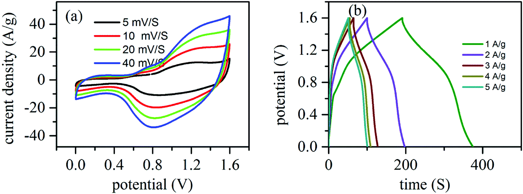 | ||
| Fig. 9 Two electrode electrochemical characterization of NiCo-MOF/rGO-2//rGO (a) CV plots and (b) GCD plots. | ||
4. Conclusions
In summary, NiCo-MOF 2D nanosheet/rGO heterostructure is prepared for supercapacitor application. The hierarchical NiCo-MOF 2D nanosheets are in situ grown on rGO surfaces by simple room temperature precipitation. In such hybrid structure the MOF ultrathin nanosheets provide large surface area with abundant channels for fast mass transport of ions while the conductive physical support rGO will provide rapid electron transport and can enhance the overall electrochemical performance. Moreover we tuned the ratio of rGO and MOF and the best performing hybrid material demonstrates a high specific capacitance of 1553 F g−1 at 1 A g−1 with excellent cycling capability of 83.6 after 5000 cycles of charge discharge. Additionally, the assembled asymmetric device showed excellent energy densities of 44 W h kg−1 at power density of 3168 W kg−1. The result obtained in this report illustrates as a rational construction of NiCo-MOF 2D nanosheets/rGO heterostructure can provide a candidate approach to design advanced functional materials for energy storage applications.Conflicts of interest
The authors state as There are no conflicts to declare.Acknowledgements
This work is financial supported by China Postdoctoral Science Foundation (Grant No. 2018M633511), the National Natural Science Foundation (Grant No. 61671368, 61172041, 91123018 and 61404103) and the Fundamental Research Funds for the Central Universities. The authors thank all the financial supporters. Additionally, we thank Shaanxi Province for the postdoctoral allowance they provide.Notes and references
- R. A. Huggins, Solid State Ionics, 2000, 134, 179–195 CrossRef CAS.
- P. Simon, Y. Gogotsi and B. Dunn, Science, 2014, 343, 1210–1211 CrossRef CAS.
- J. R. Miller and P. Simon, Science, 2008, 321, 651 CrossRef CAS.
- Y. Zhang, H. Feng, X. Wu, L. Wang, A. Zhang, T. Xia, H. Dong, X. Li and L. Zhang, Int. J. Hydrogen Energy, 2009, 34, 4889–4899 CrossRef CAS.
- F. Meng, Z. Li, W. Xu, M. Wang, Y. Liu, J. Zhang, W. Wang, D. Zhao and X. Guo, J. Mater. Chem. A, 2013, 1, 7235–7241 RSC.
- G. Wang, L. Zhang and J. Zhang, Chem. Soc. Rev., 2012, 41, 797–828 RSC.
- Y. Meng, K. Wang, Y. Zhang and Z. Wei, Adv. Mater., 2013, 25, 6985–6990 CrossRef CAS.
- J. Zhang, Z. Zhang, Y. Jiao, H. Yang, Y. Li, J. Zhang and P. Gao, J. Power Sources, 2019, 419, 99–105 CrossRef CAS.
- C. Sengottaiyan, R. Jayavel, R. G. Shrestha, T. Subramani, S. Maji, J. Ho Kim, J. P. Hill, K. Ariga and L. K. Shrestha, Bull. Chem. Soc. Jpn., 2019, 92, 521–528 CrossRef CAS.
- J. Li, Y. Wang, W. Xu, Y. Wang, B. Zhang, S. Luo, X. Zhou, C. Zhang, X. Gu and C. Hu, Nano Energy, 2019, 57, 379–387 CrossRef CAS.
- J. Yang, X. Xiao, P. Chen, K. Zhu, K. Cheng, K. Ye, G. Wang, D. Cao and J. Yan, Nano Energy, 2019, 58, 455–465 CrossRef CAS.
- S.-M. Chen, R. Ramachandran, V. Mani and R. Saraswathi, Int. J. Electrochem. Sci., 2014, 9, 4072–4085 Search PubMed.
- Z. S. Iro, C. Subramani and S. S. Dash, Int. J. Electrochem. Sci., 2016, 11, 10628–10643 CrossRef CAS.
- S. Zheng, X. Li, B. Yan, Q. Hu, Y. Xu, X. Xiao, H. Xue and H. Pang, Adv. Energy Mater., 2017, 7, 1602733 CrossRef.
- F. Wang, X. Wu, X. Yuan, Z. Liu, Y. Zhang, L. Fu, Y. Zhu, Q. Zhou, Y. Wu and W. Huang, Chem. Soc. Rev., 2017, 46, 6816–6854 RSC.
- L. Wang, Y. Han, X. Feng, J. Zhou, P. Qi and B. Wang, Coord. Chem. Rev., 2016, 307, 361–381 CrossRef CAS.
- C. R. Mulzer, L. Shen, R. P. Bisbey, J. R. McKone, N. Zhang, H. D. Abruna and W. R. Dichtel, ACS Cent. Sci., 2016, 2, 667–673 CrossRef CAS.
- K. M. Choi, H. Mo Jeong, J. Hyo Park, Y.-B. Zhang, J. K. Kang and O. M. Yaghi, ACS Nano, 2014, 8, 7451–7457 CrossRef CAS.
- L. Kang, S.-X. Sun, L.-B. Kong, J.-W. Lang and Y.-C. Luo, Chin. Chem. Lett., 2014, 25, 957–961 CrossRef CAS.
- H. B. Wu and X. W. David Lou, Sci. Adv., 2017, 3, eaap9252 CrossRef PubMed.
- M. Khan, M. N. Tahir, S. F. Adil, H. U. Khan, M. R. H. Siddiqui, A. A. Al-warthan and W. Tremel, J. Mater. Chem. A, 2015, 3, 18753–18808 RSC.
- A. L. M. Reddy, S. R. Gowda, M. M. Shaijumon and P. M. Ajayan, Adv. Mater., 2012, 24, 5045–5064 CrossRef CAS.
- D. Chen, G. Ji, Y. Ma, J. Y. Lee and J. Lu, ACS Appl. Mater. Interfaces, 2011, 3, 3078–3083 CrossRef CAS.
- A. L. M. Reddy, M. M. Shaijumon, S. R. Gowda and P. M. Ajayan, Nano Lett., 2009, 9, 1002–1006 CrossRef CAS.
- D. P. Singh, C. E. Herrera, B. Singh, S. Singh, R. K. Singh and R. Kumar, Mater. Sci. Eng., C, 2018, 86, 173–197 CrossRef CAS.
- R. Kumar, S. Sahoo, E. Joanni, R. K. Singh, W. K. Tan, K. K. Kar and A. Matsuda, Prog. Energy Combust. Sci., 2019, 75, 100786 CrossRef.
- R. Kumar, E. Joanni, R. Savu, M. S. Pereira, R. K. Singh, C. J. L. Constantino, L. T. Kubota, A. Matsuda and S. A. Moshkalev, Energy, 2019, 179, 676–684 CrossRef CAS.
- R. Kumar, M. M. Abdel-Galeil, K. Z. Ya, K. Fujita, W. K. Tan and A. Matsuda, Appl. Surf. Sci., 2019, 481, 296–306 CrossRef CAS.
- R. Kumar, R. Matsuo, K. Kishida, M. M. Abdel-Galeil, Y. Suda and A. Matsuda, Electrochim. Acta, 2019, 303, 246–256 CrossRef CAS.
- R. Kumar, A. V. Alaferdov, R. K. Singh, A. K. Singh, J. Shah, R. K. Kotnala, K. Singh, Y. Suda and S. A. Moshkalev, Composites, Part B, 2019, 168, 66–76 CrossRef CAS.
- R. K. Singh, R. Kumar, D. P. Singh, R. Savu and S. A. Moshkalev, Mater. Today Chem., 2019, 12, 282–314 CrossRef CAS.
- Y. Zhou, Z. Mao, W. Wang, Z. Yang and X. Liu, ACS Appl. Mater. Interfaces, 2016, 8, 28904–28916 CrossRef CAS.
- D. J. Ashworth and J. A. Foster, J. Mater. Chem. A, 2018, 6, 16292–16307 RSC.
- H. Yin and Z. Tang, Chem. Soc. Rev., 2016, 45, 4873–4891 RSC.
- H. Zhao, Y. Zhu, F. Li, R. Hao, S. Wang and L. Guo, Angew. Chem., 2017, 56, 8766–8770 CrossRef CAS.
- D. Yu, K. Goh, H. Wang, L. Wei, W. Jiang, Q. Zhang, L. Dai and Y. Chen, Nat. Nanotechnol., 2014, 9, 555–562 CrossRef CAS.
- L. Huang, D. Chen, Y. Ding, S. Feng, Z. L. Wang and M. Liu, Nano Lett., 2013, 13, 3135–3139 CrossRef CAS.
- R. Wang, X. Yan, J. Lang, Z. Zheng and P. Zhang, J. Mater. Chem. A, 2014, 2, 12724 RSC.
- L. G. Beka, X. Li, X. Wang, C. Han and W. Liu, RSC Adv., 2019, 9, 26637–26645 RSC.
- Y. Zhao, M. Liu, B. Fan, Y. Chen, W. Lv, N. Lu and R. Li, Catal. Commun., 2014, 57, 119–123 CrossRef CAS.
- J. Liu, J. He, L. Wang, R. Li, P. Chen, X. Rao, L. Deng, L. Rong and J. Lei, Sci. Rep., 2016, 6, 23667 CrossRef CAS.
- C. Qu, L. Zhang, W. Meng, Z. Liang, B. Zhu, D. Dang, S. Dai, B. Zhao, H. Tabassum, S. Gao, H. Zhang, W. Guo, R. Zhao, X. Huang, M. Liu and R. Zou, J. Mater. Chem. A, 2018, 6, 4003–4012 RSC.
- J. Jin, Y. Zheng, S.-z. Huang, P.-p. Sun, N. Srikanth, L. B. Kong, Q. Yan and K. Zhou, J. Mater. Chem. A, 2019, 7, 783–790 RSC.
- J. Hong, S.-J. Park and S. Kim, Electrochim. Acta, 2019, 311, 62–71 CrossRef CAS.
- F. Israr, D. K. Kim, Y. Kim and W. Chun, Quim. Nova, 2016, 39, 669–675 CAS.
- X. Wang, N. Yang, Q. Li, F. He, Y. Yang, B. Wu, J. Chu, A. Zhou and S. Xiong, J. Solid State Chem., 2019, 277, 575–586 CrossRef CAS.
- X. Guo, T. Xing, Y. Lou and J. Chen, J. Solid State Chem., 2016, 235, 107–112 CrossRef CAS.
- J. F. Moulder, W. F. Stickle, P. E. Sobol and K. D. Bomben, Handbook of X-ray Photoelectron Spectroscopy, Perkin-Elmer Corporation, United Stales of America, 1992 Search PubMed.
- J. Yang, C. Yu, X. Fan, S. Liang, S. Li, H. Huang, Z. Ling, C. Hao and J. Qiu, Energy Environ. Sci., 2016, 9, 1299–1307 RSC.
- J. Shi, X. Li, G. He, L. Zhang and M. Li, J. Mater. Chem. A, 2015, 3, 20619–20626 RSC.
- X. Zhanga, S. Liua, Y. Zanga, R. Liua, G. Liua, G. Wanga, Y. Zhanga, H. Zhanga and H. Zhaoa, Nano Energy, 2016, 30, 93–102 CrossRef.
- X. Ma, H. Wang, Q. Wu, J. Zhang, D. Liang, S. Lu and Y. Xiang, J. Electrochem. Soc., 2019, 166, A236–A244 CrossRef CAS.
- M. U. Anu Prathap and R. Srivastava, Nano Energy, 2013, 2, 1046–1053 CrossRef CAS.
- Z. Fan, J. Chen, K. Cui, F. Sun, Y. Xu and Y. Kuang, Electrochim. Acta, 2007, 52, 2959–2965 CrossRef CAS.
- X. Li, G. Xu, F. Deng, C. Chen, J. Li and F. Kang, Electrochemistry, 2017, 85, 461–468 CrossRef CAS.
- F. Cao, M. Gan, L. Ma, X. Li, F. Yan, M. Ye, Y. Zhai and Y. Zhou, Synth. Met., 2017, 234, 154–160 CrossRef CAS.
- S. Zhao, L. Zeng, G. Cheng, L. Yu and H. Zeng, Chin. Chem. Lett., 2019, 30, 605–609 CrossRef CAS.
- J. Yang, P. Xiong, C. Zheng, H. Qiu and M. Wei, J. Mater. Chem. A, 2014, 2, 16640–16644 RSC.
- H. Gholipour-Ranjbar, M. Soleimani and H. R. Naderi, New J. Chem., 2016, 40, 9187–9193 RSC.
- P. Wen, P. Gong, J. Sun, J. Wang and S. Yang, J. Mater. Chem. A, 2015, 3, 13874–13883 RSC.
- R. Abazari, S. Sanati, A. Morsali, A. M. Z. Slawin, C. L. Carpenter-Warren, W. Chen and A. Zheng, J. Mater. Chem. A, 2019, 7, 11953–11966 RSC.
- P. Yu, Y. Liang, H. Dong, H. Hu, S. Liu, L. Peng, M. Zheng, Y. Xiao and Y. Liu, ACS Sustainable Chem. Eng., 2018, 6, 15325–15332 CrossRef CAS.
- L. G. Beka, X. Li and W. Liu, Sci. Rep., 2017, 7, 2105 CrossRef PubMed.
| This journal is © The Royal Society of Chemistry 2019 |