
 Open Access Article
 This Open Access Article is licensed under a Creative Commons Attribution-Non Commercial 3.0 Unported Licence
A microbial fuel cell configured for the remediation of recalcitrant pollutants in soil environment†
Gunda Mohanakrishna a,
Riyadh I. Al-Raoush*a,
Ibrahim M. Abu-Reeshb and
Deepak Pantc
a,
Riyadh I. Al-Raoush*a,
Ibrahim M. Abu-Reeshb and
Deepak Pantc
aDepartment of Civil and Architectural Engineering, College of Engineering, Qatar University, P O Box 2713, Doha, Qatar. E-mail: riyadh@qu.edu.qa
bDepartment of Chemical Engineering, College of Engineering, Qatar University, P O Box 2713, Doha, Qatar
cSeparation & Conversion Technologies, VITO - Flemish Institute for Technological Research, Boeretang 200, 2400 Mol, Belgium
First published on 13th December 2019
Abstract
A pristine soil environment supports a healthy soil biodiversity, which is often polluted with recalcitrant compounds. The bioelectrochemical remediation of the contaminated soils using bioelectrochemical systems (BESs) is gaining significant attention with respect to the restoration of the soil ecosystem. In this direction, a microbial fuel cell (MFC, an application of BES), was employed for the treatment of total petroleum hydrocarbons (TPHs) in a soil microenvironment at three ranges of pollution (loading conditions – 320, 590 and 840 mg TPH per L). TPHs degraded effectively in the soil-electrode vicinity in the range of 158 mg TPHR per L (320 mg TPH per L) and 356 mg TPHR per L (840 mg TPH per L). The study also demosntrated a maximum bioelectrogenesis of 286.7 mW m−2 (448 mV at 100 Ω) at the highest TPH loading concentration studied (840 mg TPH per L). The conditions prevailing in the soil MFC also facilitated the removal of sulfates (114 mg SO42− per L; 62.64%) and the removal of total dissolved solids (910 mg TDS per L, 12.08%) at an 840 mg TPH per L loading condition. The pH of the outlet wastewater prevailing in the mild alkaline range of 7.6 and 8.4, along with improved sulfate and TPH removal in the respective conditions suggested suitable conditions for sulfate-reducing bacteria (SRB). This study also signified the sustainability of the process for the effective treatment of hydrocarbon contaminated soil that also generates green energy.
1. Introduction
The rapid expansion and development of industrial activities increased the discharge of pollutants into the environment that causes a deterioration of water resources. It consequently resulted in the deterioration of the quality of soil and sediments, which further affected the quality of the entire ecosystem.1,2 Currently, petroleum-based resources are considered as the major source of energy required for industrial and human activities. This resulted in the release of petroleum hydrocarbon pollutants to various components of the environment such as soil and water.3–6 Alkanes, aromatics, nitrogen–sulphur–oxygen compounds (NSO) and asphaltenes are the main fractions of petroleum hydrocarbons.7,8 The alkanes are C1 (methane) to C40 compounds with straight-chain or branched-chain hydrocarbons, whereas aromatic compounds contains at least one benzene ring in the structure. NSOs and asphaltenes are complex molecules that exert complex toxic effects on the ecosystem. The release of crude oil constituents into the environment has the potential to exhibit adverse effects on ecology and human health.9–11 Environmental contamination and ecosystem deterioration are a global concern that demands for innovative and cost-effective remediation technologies.12,13 Total petroleum hydrocarbons (TPHs) are lethal to beneficial soil organisms and human beings, and create a serious concern among the research community and governments.14,15 Chronic petrogenic contamination shows adverse effects on various components of the ecosystem.16,17 This has demanded the research on remediation techniques for petroleum contamination. Based on the complexity of the pollutants and sites of contamination, and to avoid secondary pollutants from the treatment process, biological processes show merits over chemical and physico-chemical processes.18,19Currently, an increased number of bioremediation technologies using plants (phytoremediation), bacteria, algae and fungi are being explored for the degradation of TPH-contaminated surfaces and subsurface soils.8,20–22 A novel method called bioelectrochemical systems (BES), such as microbial fuel cells (MFCs) and microbial electrolysis cells (MECs), which deal with the interface of a biofilm and electrode environment, has shown superior functions for the degradation of petrogenic pollutants.23–25 The degradation or oxidation of pollutants in an anodic environment has facilitated green energy generation. Several other pollutants, such as sulfates, nitrates, and chemical oxygen demand (COD), can also be treated simultaneously by BES.26,27 The electrochemically-active biofilm present on the anode of MFCs generates bioelectricity from the treatment of organics, whereas MECs treat specific pollutants under mild external applied potentials for different types of pollutants.28–30 The biological and electrochemical effects combined in BES systems create hybrid mechanisms that facilitate complex bio-electrochemical treatment processes.32–34 The bioelectrochemical energy generating from the system is green in nature and non-pollutant. It treats complex pollutants deteriorating the environment.
Herein, the present study was aimed to remediate soil contaminated with recalcitrant petroleum-based hydrocarbons via a novel soil MFC configuration. Petroleum hydrocarbons present in the soil act as an electron donor and carbon electrodes as electron acceptors that develop a biopotential in the soil environment. The combination of a generated biopotential and associated microbial activity help to generate biological electricity in concurrence with bioelectro-remediation. At this stage of the study, the primary focus was towards soil bioelectro-remediation, MFC performance and its evaluation of sustainability, rather than the microbial aspects.
2. Experimental
2.1 Soil based microbial fuel cell (MFC)
A rectangular cuboid-shaped, soil-based MFC was designed to evaluate the bioelectrochemical degradation of hydrocarbon contaminated soil. A mixture of peat moss and soil in the proportion of 70![[thin space (1/6-em)]](https://www.rsc.org/images/entities/char_2009.gif) :30 was used to develop the column for MFC. The ratio of soil and peat moss was adapted from the gardening practice that's being practiced at Qatar University, Qatar. The characteristics of the mixture were identified as pH 7.45 (1:10 ratio in water), soil consistency – loose, color – brown and water holding capacity – 8.6%. The Perspex-based MFC having dimensions of height – 14 cm as well as a length and width – 9 cm was filled with the soil and peat moss mixture.35 The soil bed constituted about 70% (up to 10 cm) of the total height of the MFC (Fig. S1†). This supported placing the electrodes horizontally in the soil matrix. Anode and cathode electrodes with the dimensions of a 5 cm length, 5 cm height and 1 cm width were chosen. The anode with a developed electroactive biofilm (bioanode) in the suspended reactor (using petroleum refinery wastewater as the substrate) was placed in the sub-surface of the soil (2 cm below the surface of the soil). Proper care was taken to keep the biofilm intact during the placement of the electrode. A fresh cathode cleaned with hot water was also placed horizontally on the soil column (at the surface). Using an anode with a well-developed biofilm and a fresh cathode electrode helped to maintain the biopotential only through the anodic activity. The possibility of biofilm formation on the cathode was minimized by washing the cathode on every seventh day. The outlet of the MFC was placed at an equal height of the soil surface to maintain a constant water table in the soil during water recirculation. These conditions mimicked the surface to subsurface conditions of the soil, which was the target zone for the degradation of the petroleum hydrocarbons. Non-corrosive titanium wire was used as the connector of the anode and cathode electrodes. The inlet and outlet ports fed the reactor in the up-flow direction and recirculated the petroleum wastewater at known concentrations. Parallel to the soil MFC, a control reactor was also operated using a similar set-up, except for the placement of the electrodes to evaluate the function of the soil microorganisms in treating the produced water.
:30 was used to develop the column for MFC. The ratio of soil and peat moss was adapted from the gardening practice that's being practiced at Qatar University, Qatar. The characteristics of the mixture were identified as pH 7.45 (1:10 ratio in water), soil consistency – loose, color – brown and water holding capacity – 8.6%. The Perspex-based MFC having dimensions of height – 14 cm as well as a length and width – 9 cm was filled with the soil and peat moss mixture.35 The soil bed constituted about 70% (up to 10 cm) of the total height of the MFC (Fig. S1†). This supported placing the electrodes horizontally in the soil matrix. Anode and cathode electrodes with the dimensions of a 5 cm length, 5 cm height and 1 cm width were chosen. The anode with a developed electroactive biofilm (bioanode) in the suspended reactor (using petroleum refinery wastewater as the substrate) was placed in the sub-surface of the soil (2 cm below the surface of the soil). Proper care was taken to keep the biofilm intact during the placement of the electrode. A fresh cathode cleaned with hot water was also placed horizontally on the soil column (at the surface). Using an anode with a well-developed biofilm and a fresh cathode electrode helped to maintain the biopotential only through the anodic activity. The possibility of biofilm formation on the cathode was minimized by washing the cathode on every seventh day. The outlet of the MFC was placed at an equal height of the soil surface to maintain a constant water table in the soil during water recirculation. These conditions mimicked the surface to subsurface conditions of the soil, which was the target zone for the degradation of the petroleum hydrocarbons. Non-corrosive titanium wire was used as the connector of the anode and cathode electrodes. The inlet and outlet ports fed the reactor in the up-flow direction and recirculated the petroleum wastewater at known concentrations. Parallel to the soil MFC, a control reactor was also operated using a similar set-up, except for the placement of the electrodes to evaluate the function of the soil microorganisms in treating the produced water.
2.2 Loading of hydrocarbon pollutants to the soil MFC and MFC operation
The bioelectrochemical degradation of petroleum hydrocarbons and bioelectrogenesis was evaluated at three different TPH loading conditions of 320, 590 and 840 mg TPH per L in batch mode operation at room temperature. The first loading condition of 320 mg TPH per L was evaluated for 3 consecutive cycles, followed by 590 mg TPH per L for 3 cycles. In the case of the last loading condition of 840 mg TPH per L, it was operated for 2 cycles. A total of 1 L of synthetic produced water with the required concentration of TPH (in the reservoir) was recirculated through the MFC using a closed loop system at a recirculation rate of 20 mL min−1. The synthetic produced water (all compositions are in g L−1, NH4Cl, 0.25; FeSO4, 0.25; CaCl2·2H2O, 15.0; KCl, 2.0; MgCl2, 15.0; NaCl, 55.0; Na2SO4, 2.0; NaHCO3, 1.0; and H3BO3, 0.25) was diluted 12 times to bring the total dissolved solids (TDS) to 7500 mg TDS per L (approx.). To achieve 320, 590 and 840 mg TPH per L, commercial gear oil was added at a concentration of 0.15, 0.25 and 0.40 mL L−1, respectively. The water holding capacity of the MFC was determined as 440 mL with a void ratio of 0.54 (total volume of the column, 0.81 L). The seven days of operation was maintained constant for each batch cycle. Anode and cathode electrodes were connected across the 100 Ω resistor to keep the active electron discharge in the system. Since the anode was adapted for the treatment of the petroleum hydrocarbon, stable bioelectricity production was recorded over three days of operation. The control reactor was also operated under the same conditions at three different concentrations of TPH. The control reactor operation provided the specific function of the electroactive bacteria for the aim of the present study. Prior to running the experiment and control operations, the soil column was run with produced water recirculation, followed by the for control and soil MFC running for three days to saturate the soil column with the ingredient pollutants of the produced water. Precaution was taken to eliminate the error due to the adsorption phenomenon of the pollutants in the soil. Liquid samples from the MFC and the control operations were collected from the reservoir at the end of each cycle and stored at 4 °C for further analysis.2.3 Analysis
The bioelectrogenesis of the soil MFC was measured in terms of voltage by the multi-meter. The current and power were calculated by applying Ohm's law. A variable resistor box (50 Ω to 30 kΩ) was used to analyze the polarization behavior of the electrode at each TPH loading condition.31,36 Anode and cathode potentials were measured in a three-electrode configuration using an Ag/AgCl reference electrode.28,37 The relative decrease in the anode potential (RDAP) was analyzed to assess the sustainability of the MFC.38 The liquid samples collected from the soil MFC were analyzed for pH, TDS, COD, sulfates and TPH. The methods outlined in the Standard Methods for the Examination of Water and Wastewater39 were adapted. A testing kit supplied by LANGE was used for the COD measurements. The detection and quantification of the diesel range organics (DROs) was followed by adapting methods outlined in USEPA method 8000B in combination with USEPA method 8015.3. Results and discussion
3.1 Degradation of petroleum hydrocarbons in the subsurface soil environment of MFC
Petroleum hydrocarbons are complex, but can be degraded by specific bacteria at a relatively lower rate compared to simple wastewater of a biological origin. Bioelectrochemical systems adapt mixed consortia from environmental sources for the degradation of various types of pollutants, which also helps for the generation of green energy in the form of bioelectricity.40 In the present study, the observed trend of TPH degradation at the three different loading conditions clearly depicted the efficiency of the soil MFC (Fig. 1). During the first cycle of operation (inlet substrate concentration, 320 mg TPH per L), a substrate degradation of 142 mg TPH per L (44.38%) was recorded during the 7 days of operation. Among the 3 cycles of operation with 320 mg TPH per L, a maximum TPH degradation of 158 mg L−1 was registered, which represented a 49.38% removal efficiency (average of 320 mg TPH per L, 146.7 mg TPHR per L and 45.83%). Control experiments were performed to compare the metabolic action of soil bacteria alone and to identify the specific function of the anodic electrogenic biofilm on TPH degradation. Under the same loading condition (320 mg TPH per L), the control experiments depicted a maximum TPH degradation of 28 mg L−1 (TPH degradation efficiency, 8.75%) with an average degradation of 23.3 mg TPH per L (7.29%) (Fig. 1b). | ||
| Fig. 1 Degradation of the total petroleum hydrocarbons during the three loading conditions of the (a) soil MFC and in the (b) control operations. Cycle numbers 1–3 represent 320 mg TPH per L, 4–6 represent 590 mg TPH per L and 7–8 represent 840 mg TPH per L. | ||
The increase in the TPH loading to 590 mg TPH per L indicated a substantial improvement in the substrate removal, registering a maximum value of 248 mg L−1 (42.03%). The average TPH degradation in the three cycles of operation with 590 mg TPH per L was 235 mg L−1, which represented a 39.9% removal efficiency. The increase in the TPH loading resulted in an improvement in TPH degradation. The control reactor operation with the same TPH loading of 590 mg TPH per L, depicted a maximum TPH degradation of 45 mg L−1 (TPH degradation efficiency, 7.63%) and an average degradation of 38.6 mg TPH per L (6.55%). The further increase in the TPH concentration to 840 mg TPH per L also resulted in a similar trend with respect to substrate degradation. The maximum and average TPH removal were recorded as 356 mg L−1 and 340 mg L−1, respectively. Similarly, the TPH degradation efficiency was also recorded as 42.38% (maximum) and 40.5% (average) (Fig. 1a). The substrate degradation in the control reactor was limited to a maximum degradation of 40 mg TPH per L (average, 35 mg TPH per L) with an efficiency of 4.76% (average, 4.17%) (Fig. 1b). Interestingly, the TPH degradation efficiency of the MFC operation at 590 and 840 mg TPH per L loading were comparable, which also claimed suitability of the MFC system for bioelectro-remediation of hydrocarbon contaminated soils. The continuous recirculation of the wastewater in the soil MFC was maintained, which might have facilitated the passing of the wastewater to the vicinity of the electrodes and the exposure of the wastewater to the bioelectrochemical reactions. Since the recirculation of the liquid content was designed in an up-flow direction, a uniform concentration of the pollutants in the soil environment was possible. However, the application of this method directly to the contaminated sites requires an understanding of the geological and physico-chemical nature of the respective soils.
3.2 Diesel range organics degradation
The primary details of the evolution of TPH in the MFC were identified by tracing the DROs. DROs are highly regarded as an intermediate fraction of the petroleum refining process. Diesel hydrocarbon compounds (specifically long chain alkenes) are the most abundant compounds in DROs, which were considered to identify the evolution pattern in the soil MFC and control operations. Among the three TPH concentrations studied, total DRO degradation was increased with the increase in the available TPH concentrations (Fig. 2). The highest DRO degradation of 34.69 mg DROs per L was registered with an 840 mg TPH per L variation, followed by 590 mg TPH per L (25.98 mg DROs per L) and 320 mg TPH per L (17.16 mg DROs per L), which clearly depicted the bioelectrochemical potential of the MFC towards DRO removal (Fig. 2a). On the contrary to the DRO removal, its removal efficiency decreased with an increase in the total DRO concentration. In the case of the 320 mg TPH per L loading condition, a maximum DRO removal efficiency of 38.78% was recorded, which further decreased to 34.41 and 31.52% for the 590 and 840 mg TPH per L conditions, respectively (Fig. 2b). Both the removal and removal efficiency of the DROs was several times higher than the control experiments, which also corroborated the capability of the MFC towards TPH treatment (Fig. 2a and b).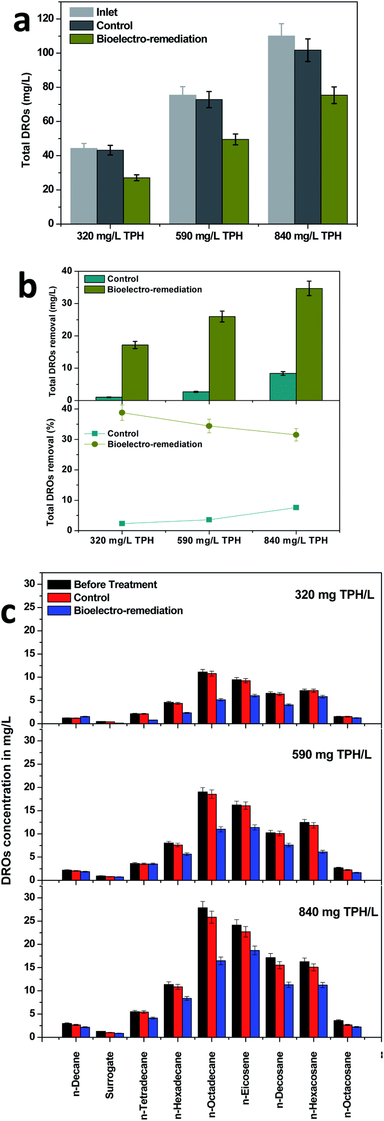 | ||
| Fig. 2 Pattern of the diesel range organic (DRO) degradation in the bioelectroremediation process and respective control operations. (a) Total concentration of the DROs, (b) DRO removal concentration and DRO removal efficiency and (c) concentrations of diverse DROs in the MFC and control operation. | ||
Further analysis was performed to identify the individual DRO compound degradation in the MFC and control operations. Compared to the control operation, the MFC visualized the removal of the DROs with the three loading conditions studied. All nine DRO compounds analyzed degraded significantly over the MFC operation. However, a higher affinity towards bioelectrochemical degradation was regarded with n-octadecane, n-eicosene and n-decosane (DROs). In all the TPH concentrations, these three compounds collectively contributed more than 50% of the total DROs degraded. Contrary to the decrease in the concentration over the MFC treatment, n-decane showed an increase in its concentration under the 320 mg TPH per L loading condition. n-Decane was the simplest among the analyzed DROs. The gradual breakdown of the higher TPH compounds or DROs via bioelectrochemical remediation might have resulted in the n-decane production that resulted in an increased concentration. The higher removal efficiency with the larger molecules rather than smaller molecules such as n-docane, surrogate and n-tetradecane might have been due to the production of smaller compounds from the degradation of the higher carbon compounds such as n-octadecane, n-eicosene and n-decosane. A previous study that was performed with petroleum refinery wastewater under applied potentials showed a higher efficiency towards DRO removal (>80%).41 The limited efficiency in the present study was attributed to the soil environment, which provided relatively less contact with the electrode surface. On the other hand, the degradation in the present study was due to the bioelectrochemical potential that developed by the system rather than the external applied potential in the previous study.
3.3 Soil MFC performance
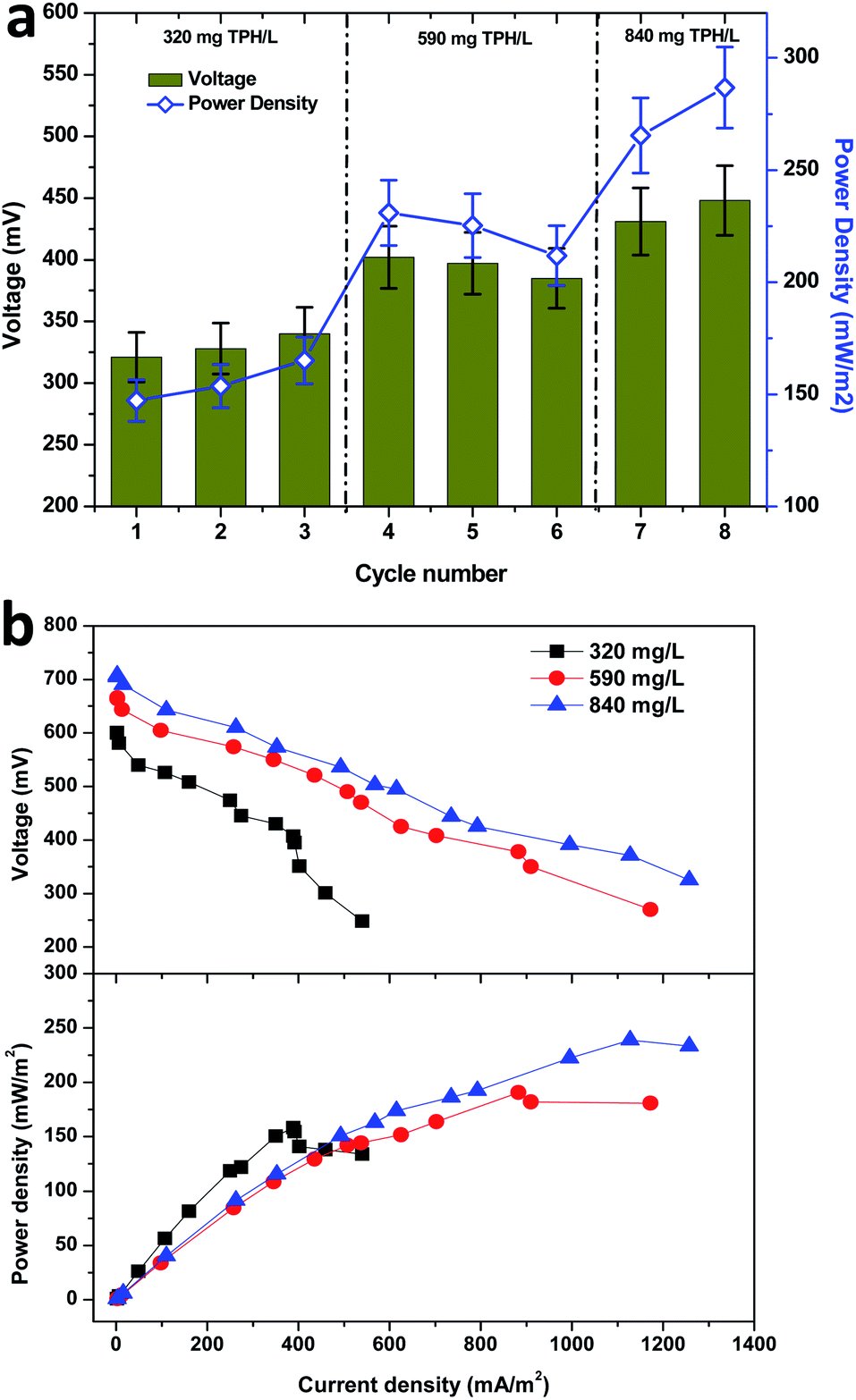 | ||
| Fig. 3 (a) Bioelectricity generation potential of the soil-based microbial fuel cell depicting the voltage generation during the three TPH loading conditions with a 100 ohms resistor. (b) Polarization behavior of the MFC under operation using the three TPH loading conditions. | ||
Starting from the fourth cycle of operation, the TPH loading of 590 mg TPH per L was adapted and operated consecutively for three cycles. Among the three operating cycles with 590 mg TPH per L in cycle 4, a maximum power density of 230.9 mW m−2 (402 mV) was developed across the resistance. Considering the average power densities for the 320 mg TPH per L loading operation (155.3 mW m−2) and 590 mg TPH per L loading (222.6 mW m−2), there was a significant power improvement (67.2 mW m−2, about 40%). This clearly depicted the contribution of the available TPH in the soil matrix towards the bioelectricity generation. Upon the completion of the 3 cycles with 590 mg TPH per L, the soil MFC was fed with the next highest loading variation of 840 mg TPH per L and operated for 2 consecutive cycles, which also showed a positive sign of improved power generation. Upon the onset of cycle 7 operation (840 mg TPH per L), the power density improved to 265.4 mW m−2, which was more than 20% over the previous cycle with 590 mg TPH per L (211.8 mW m−2) (Fig. 3a). Among all the TPH loading concentrations studied, a maximum power density of 286.7 mW m−2 was registered in the last cycle operated at 840 mg TPH per L. Among the three different TPH loading concentrations, 320 and 840 mg TPH per L showed a marginal increase in the power density with every feeding event. Contrary to the 320 and 840 mg TPH per L concentrations, the 590 mg TPH per L concentration exhibited a marginal drop. This suggested that the variation in the power density of the different operating cycles was due to a biological phenomenon.
I–V curves (polarization behavior) were recorded from the three substrate (TPH) loading concentrations using a variable resistor box. The maximum performance period of the MFC with respect to the power generation was considered as an optimum to evaluate the bioelectrochemical behavior of the MFC. The shift in recording the polarization behavior from one point to another was allowed to recover the open circuit potential to the maximum. This allowed for the recording of the bioelectrochemical activity with minimum error. In the present study that used the three loading concentrations of TPH as a substrate, the maximum electrochemical activity was found to be in accordance with their respective bioelectrogenic activities. The maximum current density and power density were increased with the increase in the TPH loading concentrations (Fig. 3b). A maximum power density of 158.1 mW m−2 (at 400 Ω; current density, 388.6 mA m−2) was registered with the 320 mg TPH per L substrate concentration. In the case of the 590 mg TPH per L concentration, the maximum power density was increased to 190.6 mW m−2 (at 200 Ω, 882.5 mA m−2). With the increase in substrate loading from 320 to 590 mg TPH per L, the power density improved by 20%. Furthermore, after increasing the TPH loading to 840 mg TPH per L, a maximum power density of 239.0 mW m−2 (1127.5 mA m−2) was recorded with a 100 Ω resistor (Fig. 3b). The polarization study also suggested that the electron discharge capacity for the MFC under the respective operating conditions was adapted. The point at which the maximum power density was recorded was denoted as the cell design point. In the present study, the cell design point decreased with the increase in the TPH loading concentration (400 Ω, 320 mg TPH per L; 200 Ω, 590 mg TPH per L and 100 Ω, 840 mg TPH per L). Considering the lowest cell design point from all the loading TPH concentrations, i.e. 100 Ω, the power density was found to increase with an increase in the substrate concentration (320 mg TPH per L, 138.0 mW m−2; 590 mg TPH per L, 182.0 mW m−2 and 840 mg TPH per L, 239.0 mW m−2). This phenomenon suggested that the electron discharge and bioelectrochemical response were directly proportional to the substrate concentration used for bioelectrogenesis.
 | ||
| Fig. 4 Evaluation of the sustainable performance of the soil MFC during the three TPH concentrations. (a) Anodic and cathodic potentials as well as the (b) sustainable power and resistance value at a relative decrease in the anodic potential (RDAP) point. | ||
The anode potential was found to decrease with the decrease in the external resistance, which depicted the electron discharge phenomenon. The lower resistance used in the anodic half-cell potential circuit facilitated the relatively higher electron discharge that resulted in a drop in the anodic potential. This phenomenon helped for the derivation of the relative decrease in the anodic potential (RDAP). The RDAP facilitated the sustainable resistor point for the stable performance of the MFC where the electron discharge and production reached equilibrium. The 320 mg TPH per L concentration unveiled a RDAP at 7.0 kΩ of the external resistance with a sustainable power generation of 0.45 mW (Fig. 4b and S2†). The RDAP resistance value increased with the increase in the TPH loading concentrations. In the case of the 590 and 840 mg TPH per L concentrations, the sustainable power was found to be 0.22 mW (at 15.5 kΩ) and 0.20 mW (at 18.0 kΩ), respectively.
3.4 Sulfate removal at various TPH concentrations
Sulfate is one of the major pollutants present in the waste/wastewater generated from petroleum industries. High sulfate concentrations present in wastewater are evidence for the adverse effects on the ecosystem. The toxic and acidic gases generated from the sulfate rich wastewater are either carcinogenic or create serious health problems, which affects the eyes, skin, lungs, intestines and nervous system.42 Material corrosion is also another challenge that is associated with sulfate rich wastewater.43,44 The reduced products may volatilize into the atmosphere and result in acid rain. Sulfate contamination also has adverse effects on the soil microenvironment, which may further led to groundwater contamination.45,46 BESs have been considered as an effective method for sulfate removal.35,47,48 In the present study bioelectricity generation was also concomitantly investigated for sulfate removal (Fig. 5). The initial concentration of sulfate was kept constant, which allowed for identifying the influence of the organic matter on the sulfate removal. Thus, it was also determined that the sulfate removal increased with an increase in the TPH concentration. At the initial TPH loading condition of 320 mg TPH per L, the highest sulfate removal of 54 mg L−1 with an efficiency of 29.67% (average, 49 mg L−1 and 26.92%) was observed (Fig. 5a). When the soil MFC was shifted to 590 mg TPH per L, an improvement in sulfate removal was found to be significant, which registered a maximum sulfate removal of 84 mg L−1 (46.15%). The improvement in the sulfate removal was compared with the registered higher TPH degradation at the higher loading conditions (Fig. 5a). Similar results were also observed when the TPH concentration was further increased to 840 mg TPH per L, which resulted in the highest sulfate removal of 114 mg L−1 (average, 113 mg L−1) with a 62.64% removal efficiency (average, 62.08%). Sulfate removal in the control reactor operation was also evaluated under the three TPH loading concentrations, which was in the range of 20 to 27 mg L−1 (Fig. 5b). Since the sulfate concentration used was constant for all of the operating conditions, a significant difference in the sulfate removal and sulfate removal efficiency was not identified with respect to the initial TPH concentration. Apart from the sulfate degradation from the mixed bacteria in the MFCs, the sulfate-reducing bacteria (SRB) also played an important role in the power generation. SRB reduced the sulfate to sulfide and then sulfide was oxidized to elemental sulfur, which was deposited on the surface of the electrode, resulting in power generation.47,49 In this case, sulfate also acted as a substrate for power generation. However, with the available analysis in the present study, the involvement of the sulfate reducing bacteria in the power generation could not be illustrated. The SRB species such as Desulfovibrio desulfuricans, Desulfuromonas acetoxidans and Desulfobulbus propionicus were confirmed to produce electricity with a concomitant sulfate reduction.47–49 The sulfate reduction in BES also exhibited the advantage of generating value-added elemental sulfur from toxic sulfide.50 | ||
| Fig. 5 Sulfate removal pattern registered in the (a) soil MFC and (b) control operations during the three loading conditions of the petroleum-based hydrocarbons. Cycle numbers 1–3 represent 320 mg TPH per L, 4–6 represent 590 mg TPH per L and 7–8 represent 840 mg TPH per L. | ||
3.5 Removal of dissolved solids
Petroleum-based wastewaters such as petroleum refinery wastewater and produced water were characterized to have high solid concentrations (TDS). Produced water contains TDS in the range of 65 to 220 g L−1, whereas refinery wastewater contains 15–45 g L−1 of TDS.51 Accidents and improper wastewater management in petroleum industries may result in soil contamination. The presence of electroactive biofilms in the MFCs facilitated the development of the bioelectrogenic conditions. The direct electric field developed an electrochemical gradient, which separated the charged ions to the oppositely-charged electrodes. This phenomenon was attributed for the removal of the salts/TDS.51,52 The employed wastewater in the present study had a TDS concentration of 7530 mg L−1, which depicted a significant removal during the MFC operation through the three different TPH loading conditions. However, the TDS removal efficiency was found to depend on the concentration of TPH in the wastewater, which was directly proportional to the bioelectrogenic potential evidenced at the respective TPH loading concentration. During the 320 mg TPH per L loading condition, a maximum TDS removal of 690 mg L−1 (average, 580 mg L−1) was achieved with a maximum removal efficiency of 9.16% (average, 7.70%; Fig. 6). Under the 590 mg TPH per L loading conditions, the TDS removal was improved to 730 mg L−1 (average, 683 mg L−1) and a 9.69% efficiency (average, 9.07%). A further increase in the substrate loading to 840 mg TPH per L also depicted an improved TDS removal and removal efficiency of 910 mg L−1 and 12.08%, respectively. In the case of the control operation, the outlet TDS concentration was estimated in the range of 7540 to 7600 mg L−1, which exhibited a marginal improvement in the TDS concentration (improvement in TDS, 10 to 70 mg L−1) from an inlet value of 7530 mg L−1 (Fig. 6b). The increase in the TDS concentration was irregular with the different TPH loading concentrations. A maximum TDS increase of 70 mg TDS per L was registered in the second cycle of the 590 mg TPH per L loading condition, whereas a minimum TDS increase was registered in the third cycle of 320 mg TPH per L and the first cycle of the 840 mg TPH per L loading conditions. The improvement in TDS might have been due to the evaporation loss that happened during the operation. Even though the inlet and outlet reservoirs used in the operational set-up were closed, it was possible to have an evaporation loss from the soil column of the reactor. The improvement in the TDS removal with respect to the TPH concentration correlated well with the power density registered at the respective conditions. This also supported the ion mobility phenomenon for the TDS removal. The membrane-less configuration adapted in the present study also facilitated the mobility of the ions towards the oppositely-charged electrodes. The microbial desalination cells (MDCs) having three chambered configurations also followed a similar principle. However, the presence of the middle chamber helped in the separation of the ions (desalination).53 Apart from the ion mobility, the direct and indirect anodic oxidation phenomena also helped to adsorb the pollutants on the anode surface.31 After eight cycles of operation for about 2 months, a gradual drop in the power density was observed. A detailed observation was made on the electrodes depicted scaling (salts deposition) on the electrode surface, which is called electrodeposition.54,55 This might have hindered the electric conductivity of the electrode due to the drop in the recorded potential. The visible difference in the TDS removal from the control and MFC operations also clearly showed the influence of the electrochemical activity in removing TDS from the wastewater used in the operation.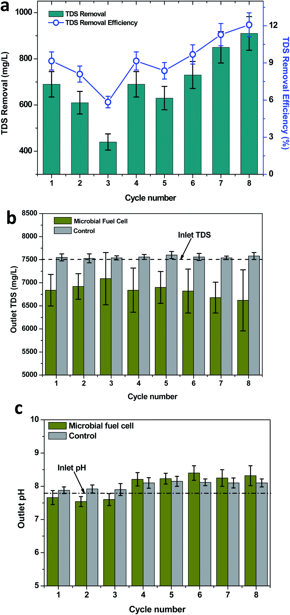 | ||
| Fig. 6 (a) Removal of the total dissolved solids (TDS) during the three loading conditions of TPH in the soil MFC. (b) Outlet TDS values evaluated in the soil MFC and control operations (the dotted line represents the value of the inlet TDS). (c) Change in pH (from inlet pH of 7.82). Cycle numbers 1–3 represent 320 mg TPH per L, 4–6 represent 590 mg TPH per L and 7–8 represent 840 mg TPH per L. | ||
3.6 Variation in the pH with TPH loading
pH is a sensitive parameter that is influenced by many biological and chemical processes in the environment. In MFCs, a pH change can be observed with the variation in the substrate degradation and the change in the components of wastewater. The wastewater that was considered in the present study was found to show an alkaline pH of 7.82. The pH was found to change by the end of each operating cycle. However, the change in the pH was found to depend on the TPH concentration adapted for the respective cycle. In the case of 320 mg TPH per L, the wastewater pH demonstrated a marginal drop towards a neutral pH (average, pH 7.6), whereas with 590 mg TPH per L, the pH was shifted to alkaline conditions (Fig. 6c). The maximum change in the pH at 590 mg TPH per L was in cycle 6 (pH = 8.4). For the highest substrate concentration studied (840 mg TPH per L), the outlet pH was 8.32 (maximum). A visible difference in the pH of the control and MFC operations was identified. In the case of control operations, the outlet pH was found to be increased in all of the TPH loading conditions (Fig. 6c). In the case of 320 mg TPH per L, the average pH was registered as 7.90, which was significantly higher than that for the MFC operation (7.6). The outlet pH in the control operations was increased with the increase in the TPH loading conditions. The 590 mg TPH per L loading conditions depicted an average outlet pH of 8.12 (maximum pH, 8.15). Upon a further increase to an 840 mg TPH per L loading condition, stability in the outlet pH (8.1) was observed. Among the bioelectrogenic conditions and control operations, a visible difference in the outlet pH was observed. This also agreed with the influence of the metabolic activities of the bioelectrochemical bacteria in TPH metabolism compared to only the soil microflora. The change in ion concentration is one factor for the change in the pH. The change in conductivity of the produced water also influenced the pH during the electrochemical sulfur production by Jain et al.56 The conditions that prevailed in the soil based MFC system may have stimulated electrochemical oxidation and oxidative desulfurization, etc., which might have induced a change in the pH of the produced water.57–60 The TDS removal that was registered during the MFC operation might have been one of the reasons for the change in the pH, which was determined upon evaluating the anion and cation concentrations in the wastewater and their respective charges. On the other hand, the change in the sulfate concentrations also predominantly changed the solution pH. The activity of the SRB improved with an increase in the availability of organic matter, which in turn resulted in the increased pH.61 For the 590 and 840 mg TPH per L loading conditions, the higher organic matter available might have increased the activity of the SRB. Under these conditions, increased sulfate removal was identified. This might have resulted in the increase in the pH towards alkaline conditions.4 Conclusions
The present study demonstrated that the placement of the anode with a well-developed electroactive biofilm in the soil allows for the petroleum-based hydrocarbons contaminants to assist in the bioelectricity generation. It was also observed that the bioelectricity generation (average, 276 mW m2; 440 mV) increased with the increase in the hydrocarbon contaminants. The use of the soil MFCs was found to be feasible for the treatment of highly petroleum hydrocarbon contaminated soils (up to 840 mg TPH per L). The removal of the total dissolved solids (12.08% removal) and sulfates (62.64% removal) was attributed to the power generated in the soil MFC system. The improvement in the sulfate removal with an increase in the TPH loading conditions demonstrated the role of organic matter in the sulfate reduction (320 mg TPH per L, 49 mg L−1; 840 mg L−1, 113 mg L−1). In this study, the importance of bioelectrochemistry in the treatment of complex and recalcitrant compounds has been illustrated. The pattern of the diesel range organic (DROs) degradation depicted that the high carbon molecules degraded to lower carbon molecules. The RDAP analysis also depicted the sustainability of the soil MFCs.Conflicts of interest
There are no conflicts to declare.Acknowledgements
This publication was made possible by NPRP grant # NPRP9-093-1-021 from the Qatar National Research Fund (a member of Qatar Foundation). The findings achieved herein are solely the responsibility of the authors.References
- S. P. Maletić, J. M. Beljin, S. D. Rončević, M. G. Grgić and B. D. Dalmacija, J. Hazard. Mater., 2019, 365, 467–482 CrossRef PubMed.
- A. Sharma, S. B. Singh, R. Sharma, P. Chaudhary, A. K. Pandey, R. Ansari and L. Nain, J. Environ. Manage., 2016, 181, 728–736 CrossRef CAS PubMed.
- R. M. Atlas and T. C. Hazen, Environ. Sci. Technol., 2011, 45, 6709–6715 CrossRef CAS PubMed.
- R. I. Al-Raoush, J. Contam. Hydrol., 2014, 159, 1–10 CrossRef CAS PubMed.
- M. Chen, P. Xu, G. Zeng, C. Yang, D. Huang and J. Zhang, Biotechnol. Adv., 2015, 33, 745–755 CrossRef CAS PubMed.
- S. K. Ngueleu, F. Rezanezhad, R. I. Al-Raoush and P. Van Cappellen, J. Contam. Hydrol., 2018, 219, 61–71 CrossRef CAS PubMed.
- J. Scullion, Naturwissenschaften, 2006, 93, 51–65 CrossRef CAS PubMed.
- S. J. Varjani, Bioresour. Technol., 2017, 223, 277–286 CrossRef CAS PubMed.
- W. Du, Y. Wan, N. Zhong, J. Fei, Z. Zhang, L. Chen and J. Hao, Pet. Sci., 2011, 8, 502–514 CrossRef.
- G. Liu, J. Niu, W. Guo, X. An and L. Zhao, Chemosphere, 2016, 163, 461–470 CrossRef CAS PubMed.
- K. Ramadass, M. Megharaj, K. Venkateswarlu and R. Naidu, Soil Biol. Biochem., 2015, 85, 72–81 CrossRef CAS.
- I. Dincer, Renewable Sustainable Energy Rev., 2000, 4, 157–175 CrossRef.
- M. A. I. Khan, B. Biswas, E. Smith, R. Naidu and M. Megharaj, Chemosphere, 2018, 212, 755–767 CrossRef CAS PubMed.
- M. Megharaj, I. Singleton, N. C. McClure and R. Naidu, Arch. Environ. Contam. Toxicol., 2000, 38, 439–445 CrossRef CAS PubMed.
- I. Errington, C. K. King, D. Wilkins, T. Spedding and G. C. Hose, Chemosphere, 2018, 194, 200–210 CrossRef CAS PubMed.
- U. C. Ugochukwu, A. Ochonogor, C. M. Jidere, C. Agu, F. Nkoloagu, J. Ewoh and V. U. Okwu-Delunzu, Environ. Int., 2018, 115, 38–47 CrossRef CAS PubMed.
- I. Hussain, M. Puschenreiter, S. Gerhard, P. Schöftner, S. Yousaf, A. Wang and T. G. Reichenauer, Environ. Exp. Bot., 2018, 147, 202–219 CrossRef CAS.
- A. Fakhru'l-Razi, A. Pendashteh, L. C. Abdullah, D. R. A. Biak, S. S. Madaeni and Z. Z. Abidin, J. Hazard. Mater., 2009, 170, 530–551 CrossRef PubMed.
- S. Venkata Mohan, G. N. Nikhil, P. Chiranjeevi, C. N. Reddy, M. V. Rohit, A. N. Kumar and O. Sarkar, Bioresour. Technol., 2016, 215, 2–12 CrossRef CAS PubMed.
- C. E. Cerniglia, J. Ind. Microbiol. Biotechnol., 1997, 19, 324–333 CrossRef CAS PubMed.
- Y. N. Ho, J. L. Hsieh and C. C. Huang, Bioresour. Technol., 2013, 145, 43–47 CrossRef CAS PubMed.
- A. Schwarz, E. M. Adetutu, A. L. Juhasz, A. Aburto-Medina, A. S. Ball and E. Shahsavari, Geoderma, 2019, 338, 206–215 CrossRef CAS.
- K. Chandrasekhar and S. Venkata Mohan, Bioresour. Technol., 2012, 110, 517–525 CrossRef CAS PubMed.
- G. Mohanakrishna, I. M. Abu-Reesh and R. I. Al-Raoush, J. Cleaner Prod., 2018, 190, 44–52 CrossRef CAS.
- G. Mohanakrishna, S. K. Butti, R. K. Goud and S. V. Mohan, Bioelectrochemistry, 2017, 115, 11–18 CrossRef CAS PubMed.
- X. Wang, Z. Cai, Q. Zhou, Z. Zhang and C. Chen, Biotechnol. Bioeng., 2012, 109, 426–433 CrossRef CAS PubMed.
- S. Srikanth, M. Kumar, D. Singh, M. P. Singh and B. P. Das, Bioresour. Technol., 2016, 221, 70–77 CrossRef CAS PubMed.
- G. Velvizhi, P. S. Babu, G. Mohanakrishna, S. Srikanth and S. V. Mohan, RSC Adv., 2012, 2, 1379–1386 RSC.
- Y. Zhou, N. Zhu, W. Guo, Y. Wang, X. Huang, P. Wu and J. Xian, J. Environ. Manage., 2018, 217, 565–572 CrossRef CAS PubMed.
- O. Adelaja, T. Keshavarz and G. Kyazze, Int. Biodeterior. Biodegrad., 2017, 116, 91–103 CrossRef CAS.
- G. Mohanakrishna, S. V. Mohan and P. N. Sarma, J. Hazard. Mater., 2010, 177(1–3), 487–494 CrossRef CAS PubMed.
- G. Mohanakrishna, S. K. Mohan and S. V. Mohan, Appl. Energy, 2012, 95, 31–37 CrossRef CAS.
- D. Pant, G. Van Bogaert, Y. Alvarez-Gallego, L. Diels and K. Vanbroekhoven, Environ. Eng. Manage. J., 2016, 51(8), 1897–1904 CrossRef.
- S. B. Pasupuleti, S. Srikanth, X. Dominguez-Benetton, S. V. Mohan and D. Pant, J. Chem. Technol. Biotechnol., 2016, 91(3), 624–639 CrossRef CAS.
- G. Mohanakrishna, R. I. Al-Raoush and I. M. Abu-Reesh, Bioresour. Technol., 2018, 260, 227–232 CrossRef CAS PubMed.
- L. Xu, Y. Zhao, C. Tang and L. Doherty, J. Environ. Manage., 2018, 207, 116–123 CrossRef CAS PubMed.
- B. E. Logan, B. Hamelers, R. Rozendal, U. Schröder, J. Keller, S. Freguia and K. Rabaey, Environ. Sci. Technol., 2006, 40(17), 5181–5192 CrossRef CAS PubMed.
- J. Menicucci, H. Beyenal, E. Marsili, R. A. Veluchamy, G. Demir and Z. Lewandowski, Environ. Sci. Technol., 2006, 40(3), 1062–1068 CrossRef CAS.
- APHA, Standard Methods for Examination of Water and Wastewater, American Public Health Association, American Water Works Association, Water Environment Federation, Washington, 23 edn, 2017 Search PubMed.
- W. W. Li, H. Q. Yu and Z. He, Energy Environ. Sci., 2014, 7, 911–924 RSC.
- G. Mohanakrishna, I. M. Abu-Reesh, S. Kondaveeti, R. I. Al-Raoush and Z. He, Bioresour. Technol., 2018, 253, 16–21 CrossRef CAS PubMed.
- D. M. Kargbo, R. G. Wilhelm and D. J. Campbell, Environ. Sci. Technol., 2010, 44, 5679–5684 CrossRef CAS PubMed.
- F. Liang, Y. Xiao and F. Zhao, Chem. Eng. J., 2013, 218, 147–153 CrossRef CAS.
- P. K. Dutta, K. Rabaey, Z. Yuan, R. A. Rozendal and J. Keller, Water Res., 2010, 44, 2563–2571 CrossRef CAS PubMed.
- K. Ljung, F. Maley, A. Cook and P. Weinstein, Environ. Int., 2009, 35, 1234–1242 CrossRef CAS PubMed.
- M. Åström and A. Björklund, J. Geochem. Explor., 1995, 55, 163–170 CrossRef.
- F. Zhao, N. Rahunen, J. R. Varcoe, A. Chandra, C. Avignone-Rossa, A. E. Thumser and R. C. Slade, Environ. Sci. Technol., 2008, 42, 4971–4976 CrossRef CAS PubMed.
- W. Habermann and E. H. Pommer, Appl. Microbiol. Biotechnol., 1991, 35, 128–133 CrossRef CAS.
- B. E. Logan, Nat. Rev. Microbiol., 2009, 7, 375 CrossRef CAS PubMed.
- P. Jain, M. Sharma, P. Dureja, P. M. Sarma and B. Lal, Chemosphere, 2017, 166, 96–108 CrossRef CAS.
- Z. Li, X. Zhang, J. Lin, S. Han and L. Lei, Bioresour. Technol., 2010, 101, 4440–4445 CrossRef CAS PubMed.
- G. Velvizhi and S. V. Mohan, Bioresour. Technol., 2017, 242, 77–86 CrossRef CAS PubMed.
- X. Cao, X. Huang, P. Liang, K. Xiao, Y. Zhou, X. Zhang and B. E. Logan, Environ. Sci. Technol., 2009, 43, 7148–7152 CrossRef CAS PubMed.
- H. C. Tao, M. Liang, W. Li, L. J. Zhang, J. R. Ni and W. M. Wu, J. Hazard. Mater., 2011, 189, 186–192 CrossRef CAS PubMed.
- V. G. Gude, J. Cleaner Prod., 2016, 122, 287–307 CrossRef CAS.
- P. Jain, S. Srikanth, M. Kumar, P. M. Sarma, M. P. Singh and B. Lal, Journal of Water Process Engineering, 2019, 28, 190–194 CrossRef.
- C. Yang, K. Zhao, Y. Cheng, G. Zeng, M. Zhang, J. Shao and L. Lu, Sep. Purif. Technol., 2016, 163, 153–161 CrossRef CAS.
- S. Wei, H. He, Y. Cheng, C. Yang, G. Zeng, L. Kang and C. Zhu, Fuel, 2017, 200, 11–21 CrossRef CAS.
- L. Kang, H. Liu, H. He and C. Yang, Fuel, 2018, 234, 1229–1237 CrossRef CAS.
- L. Qiu, Y. Cheng, C. Yang, G. Zeng, Z. Long, S. Wei and L. Luo, RSC Adv., 2016, 6(21), 17036–17045 RSC.
- P. Meng, H. Pei, W. Hu, Y. Shao and Z. Li, Bioresour. Technol., 2014, 157, 316–326 CrossRef CAS PubMed.
Footnote |
| † Electronic supplementary information (ESI) available. See DOI: 10.1039/c9ra06957g |
| This journal is © The Royal Society of Chemistry 2019 |