DOI:
10.1039/C9RA06467B
(Paper)
RSC Adv., 2019,
9, 33506-33518
Study on methane hydrate formation in gas–water systems with a new compound promoter
Received
18th August 2019
, Accepted 11th October 2019
First published on 18th October 2019
Abstract
The effects of a new promoter on the growth kinetics of methane hydrates were investigated using a visualized constant-pressure autoclave. The experimental results show that when the 1#, 2# and 3# unit promoter was compounded at a ratio of 2![[thin space (1/6-em)]](https://www.rsc.org/images/entities/char_2009.gif) :1:1, the induction time was shortened greatly from 30 h to 0.64 h compared to the no promoter situation. Meanwhile, there was a larger amount of hydrate formation, and final hydrate volume fraction was 83.652%. Then, the hydrate formation characteristics under different additive dosages (500 ppm, 1000 ppm, 2000 ppm, 5000 ppm) and different subcooling degrees (2.5 °C, 3.5 °C, 4.5 °C, 5.5 °C, 6.5 °C) were investigated. The new promoter at these 4 concentrations could effectively shorten the induction time. And the higher the concentration, the smaller the induction time (0.22 h at 5000 ppm). It was also found that gas consumption and hydrate production rate increased first and then decreased with increasing promoter dosage. Finally, the optimal dosage was determined to be 2000 ppm, at which the induction time was shortened to 0.52 h, and the final hydrate volume fraction was 85.74%. Under the dosage of 2000 ppm and the subcooling degree of 6.5 °C, the shortest induction time (0.29 h) and the maximum formation rate (20.950 ml h−1) were obtained among all the experimental conditions in this work. Moreover, the greater the subcooling degree, the faster the hydrate nucleation, and the shorter the induction time. However, if the subcooling degree was too high, a hydrate layer formed rapidly at the gas–liquid interface in the autoclave, which would hinder hydrate formation and lead to the reduction of hydrate volume fraction to 60.153%. Therefore, a reasonable selection of the proportioning of promoters, dosage of the promoter and formation temperature could significantly promote the formation of hydrates. The findings in this work are meaningful to hydrate associated applications and can provide useful references for the selection of hydrate promoters.
:1:1, the induction time was shortened greatly from 30 h to 0.64 h compared to the no promoter situation. Meanwhile, there was a larger amount of hydrate formation, and final hydrate volume fraction was 83.652%. Then, the hydrate formation characteristics under different additive dosages (500 ppm, 1000 ppm, 2000 ppm, 5000 ppm) and different subcooling degrees (2.5 °C, 3.5 °C, 4.5 °C, 5.5 °C, 6.5 °C) were investigated. The new promoter at these 4 concentrations could effectively shorten the induction time. And the higher the concentration, the smaller the induction time (0.22 h at 5000 ppm). It was also found that gas consumption and hydrate production rate increased first and then decreased with increasing promoter dosage. Finally, the optimal dosage was determined to be 2000 ppm, at which the induction time was shortened to 0.52 h, and the final hydrate volume fraction was 85.74%. Under the dosage of 2000 ppm and the subcooling degree of 6.5 °C, the shortest induction time (0.29 h) and the maximum formation rate (20.950 ml h−1) were obtained among all the experimental conditions in this work. Moreover, the greater the subcooling degree, the faster the hydrate nucleation, and the shorter the induction time. However, if the subcooling degree was too high, a hydrate layer formed rapidly at the gas–liquid interface in the autoclave, which would hinder hydrate formation and lead to the reduction of hydrate volume fraction to 60.153%. Therefore, a reasonable selection of the proportioning of promoters, dosage of the promoter and formation temperature could significantly promote the formation of hydrates. The findings in this work are meaningful to hydrate associated applications and can provide useful references for the selection of hydrate promoters.
1 Introduction
Hydrates are cage crystals formed by small molecules of gas and water molecules under low temperature and high pressure conditions.1,2 1 m3 of hydrate can store 180 m3 of natural gas (standard conditions).3,4 Based on their unique physical and chemical characteristics, a series of hydrate associated technologies in hydrogen storage,5,6 carbon capture,7,8 seawater desalination,9,10 cold storage refrigeration11,12 and other fields have been developed and applied. However, a series of problems such as strict hydrate formation conditions, long induction time, slow reaction rate, etc., hinder the industrialization of hydrate application technology.13–15 In the recent decade, one of the most common methods to promote hydrate formation is adding low-dose chemical additives, most of which are organic liquids and surfactants, including tetrahydrofuran (THF), sodium dodecyl sulfate (SDS), sodium dodecylbenzenesulfonate (SDBS) and nanofluid series, etc.16–21
Veluswamy et al.22 studied the effects of 5.6 mol% THF on the kinetics of methane hydrates. They found that under static conditions, the hydrate formation pressure decreased from 6.7 MPa to 2.5 MPa, indicating that a large amount of gas could be stored at moderate pressure. Zhang et al.23 investigated the effects of different dosages of SDS on the induction time of methane hydrates. For their pure water + methane system, after the addition of SDS, the induction time was reduced to less than 14 hours, while there was no hydrate formed even 3 days later without SDS addition. However, no regular relationship was observed between induction time and SDS concentration by them. Kumar24 studied the growth kinetics of CO2 hydrates under different concentrations of SDS solution. They found that the addition of SDS significantly increased the hydrate conversion rate, and hydrate conversion rate gradually increased with the increasing SDS concentration. Okutani et al.25 examined the promotion of methane hydrate formation by SDS in a static system, and found that the SDS solution at 1000 ppm could shorten the induction time to 40 min, simultaneously, enhance the formation rate and conversion rate of hydrates. Jiang et al.26 found that the addition of SDS could significantly shorten the induction time and improve the stability of hydrate formation, but SDS did not have significant effect on hydrate storage capacity.
Torre J.-P. et al.27 found that the combination of THF and SDS could greatly shorten the induction time of CO2 hydrates in both static and stirring conditions. They suggested that the additives directly affected hydrate formation, while SDS had no effect on the phase equilibrium curve of CO2 hydrates and CO2 + THF hydrates. However, the reason why the combination (THF + SDS) was so effective, and the exact mechanism has not been proposed by them. Lirio et al.28 studied the effects of SDS and THF on the gas storage capacity of CO2 hydrates. It was found that hydrates could nucleate faster in the SDS (500 ppm) and THF (5 mol%) compound solution, and the gas storage capacity was also promoted. They presented that THF formed SII (structure II) hydrates and occupied larger cavities formed by water molecules, which would promote the formation of SI hydrates formed by CO2 molecules. This effect was beneficial to capture more gas into the solid hydrates, indicating a synergistic effect of the simultaneous usage of SDS and THF. Kumar et al.29 studied the formation kinetics of CO2 hydrates at constant pressure (3.55 MPa) and constant temperature (274 K) condition with the addition of silica gel. They found that silica gel possessed large pore size and high surface area, which could improve hydrate formation rate and conversion rate. Among the three surfactants, anion (SDS) and nonionic (Tween-80) are more effective than the cationic surfactant (dodecyltrimethylammonium chloride). SDS was found to be most effective in increasing the rate of hydrate formation and reducing the induction time, and the hydrate formation rate was increased 15 times compared to static pure water system. Mohammadi et al.30,31 studied the effects of synthetic silver nano-particles and SDS on the formation rate and storage capacity of CO2 hydrates. Their results showed that SDS or silver nano-particles had no significant effect on reducing induction time or increasing the storage capacity of CO2 hydrates. But the mixture of SDS and silver nano-particles significantly increased the storage capacity of carbon dioxide. Fazlali et al.32 studied the effects of complex solutions of SDS, SDBS and CTAB on the formation characteristics of methane hydrates. Compared with the pure water system, the induction time of the system with SDS and CTAB was shortened from 58 min to 17 min (which was 2.4 times) and the formation rate was increased by 4.5 times (from 3.811 × 10⁻⁵ mol s−1 to 2.091 × 10⁻⁴ mol s−1), exhibiting pretty significant promotion effect. In conclusion, the effect of the compounding additive is much more significant than that of a single additive.
For both single hydrate promoters and complex hydrate promoters, the promotion effect varies and are limited by experimental materials and conditions. There is still a big gap from industrial applications.33 In this work, the growth characteristics of methane hydrates (induction time, hydrate volume fraction and average formation rate) in different compounding ratio, dosage, and subcooling degree were investigated in a high pressure autoclave. This study provides a reference for the study of the kinetics of methane hydrate in the presence of promoters.
2 Experiment section
2.1 Apparatus
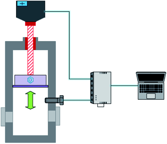
According to the requirements of the experiments, a constant pressure visualized experimental system for studying gas hydrate formation characteristics was designed and built. As showed in Fig. 1, the experimental system mainly consists of a hydrate reaction system (visualized reaction kettle), a gas supply and boosting system, a temperature control system, a data acquisition system, etc. The core device, reaction kettle, is shown in Fig. 2, and its working principle diagram is shown in Fig. 3. The piston can move downwards to maintain the system pressure in the kettle. The maximum volume of the kettle is 100 ml, which can hold liquid up to 50 ml. Besides, with 30 ml liquid injection, the gas–liquid interface can be just observed at the center of lens, which are beneficial to obtain a more clear version of images of the hydrate growth process. The working pressure range is 0–15 MPa, and the working temperature range is −10–30 °C. The temperature sensor in the kettle is platinum resistance (Pt100) with a precision of ±0.1 °C. The gas pressure in the autoclave is measured by a pressure sensor with a precision of ±0.01 MPa. The experimental temperature of the reaction kettle is controlled by a water bath with the adjusting precision of ±0.01 °C, where an antifreeze solution composed of 40% ethylene glycol and 60% distilled water is selected as the coolant.
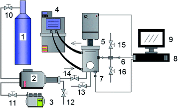 |
| | Fig. 1 Overview diagram of the gas hydrate experimental system. 1-Gas cylinder; 2-gas booster pump; 3-air compressor; 4-water bath; 5-constant pressure reactor; 6-pressure sensor; 7-temperature sensor; 8, 9-data acquisition system; 10, 11, 12, 13, 14, 15, 17-valves. | |
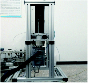 |
| | Fig. 2 Constant pressure visualized reactor. | |
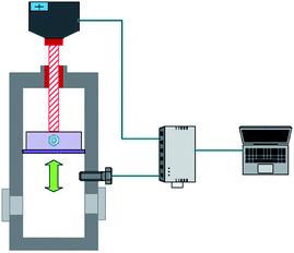 |
| | Fig. 3 Schematic diagram of the piston in the reactor. The piston can move downwards to maintain the system pressure in the kettle. | |
2.2 Materials
The methane gas used in the experiments was purchased from Changzhou Jinghua Industrial Gas Co. Ltd, and the purity was 99.8%. The experimental hydrate promoter was obtained by compounding 1#, 2# and 3# unit promoter, and was self-developed with a mass fraction of 99.0%. All of the unit promoters (1#, 2# and 3#) were surfactants. The weighing of the additives was completed by a high-precision TG328A electro-optical analytical balance with an error of 0.1 mg.
2.3 Experimental procedures
(1) The autoclave was washed three times with distilled water. 1#, 2#, and 3# unit promoters were weighed using a TG328A electro-optical analytical balance, and mixtures with different components were compounded according to the experimental requirements.
(2) Methane gas was injected and discharged for three times to remove the air in the reaction vessel and the gas line. Inject 30 ml pure water or a solution with promoters of a definite mass concentration through the inlet valve.
(3) Start the water bath circulation system to reach the required experimental temperature. Open the inlet valve, and then introduce methane gas into the reactor to a specified pressure of 5.50 MPa.
(4) An experimental system with constant pressure was obtained through the automatic movement of the piston in the reactor, where the pressure was stabilized at 5.50 MPa. Set the water bath temperature to a target value. Then start the data acquisition system. The whole experimental process could be observed through the visual window.
(5) When there was a significant temperature increase or a significant change of gas phase volume, hydrate formation began and remained this state until the temperature and volume of the reactor no longer changed.
(6) Export the experimental data, close the data acquisition system, evacuate the gas in the reaction kettle, and close the experimental equipment.
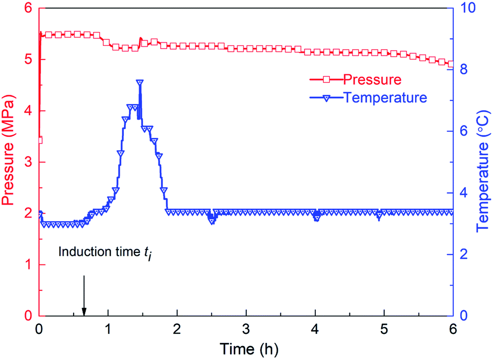
2.4 Determination of induction time
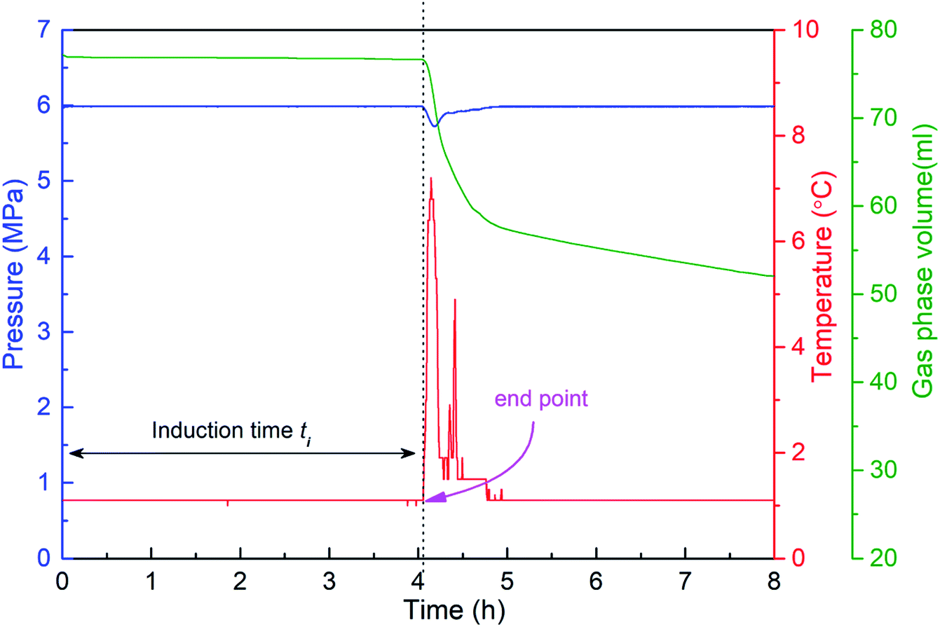
The hydrate formation induction time is an important parameter for characterizing the hydrate formation process. The current definition of induction time mainly includes microscopic induction time and macroscopic induction time34 (see Fig. 4). The microscopic induction time is the time required for the nucleation of hydrates whereas phase equilibrium state is attained before hydrate formation. However, primary nucleation, i.e., hydrate critical nuclei, cannot be detected accurately by the existing technologies so far. Since the parameters, such as system temperature T, system pressure P and gas volume V, can be determined experimentally, the macroscopic induction time is usually used to describe hydrate nucleation, which is defined as the time required for the system to reach a phase equilibrium state and a sudden change of the state parameter of the system (i.e., temperature, pressure, etc.). Therefore, for the experimental device in this paper, that is, the inflection point of the temperature–time curve is used as the end point of the induction time, as shown in Fig. 5. The interval between the time point when the system reaches the phase equilibrium temperature and the time point when the first inflection point of the temperature curve appears is regarded as the (macroscopic) induction time of the system (ti). For convenience, “induction time” means macroscopic induction time in the following sections.
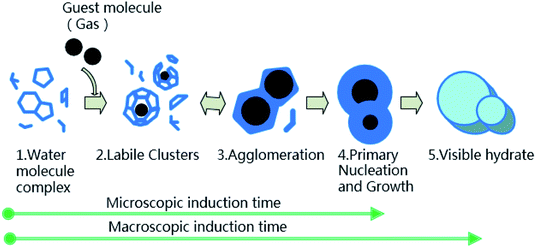 |
| | Fig. 4 Schematic diagram of gas hydrate formation.34 | |
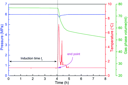 |
| | Fig. 5 Pressure, temperature and gas consumption versus time during experimental process. The sudden change of pressure, temperature or gas consumption is regarded as the end point of induction period. | |
2.5 Calculation of hydrate volume fraction
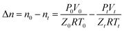
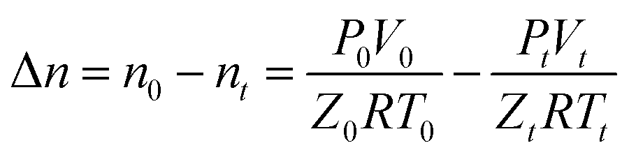
Since the experiment is carried out under constant temperature and constant pressure conditions, the gas consumption during hydrate formation can be calculated by the following equation:| |
 | (1) |
where Δn is the amount of gas consumed; T is the experimental temperature; V is the volume of gas phase, and is recorded by the data acquisition system; the subscripts 0 and t represent the parameter conditions of the reaction kettle at the reaction start time and the reaction time respectively; gas consumption volume ΔVg = V0 − Vt; Z is the gas compression factor and calculated by R–K equation of state;35 and R is the gas constant, 8.314 J mol−1 K−1.
Hydrate formation is a complex multi-phase heat and mass transfer process, which can be regarded as an exothermic chemical reaction.
| | |
nG(g) + mH2O(1) = nG·mH2O(s) + reaction heat
| (2) |
where
G refers to gas,
n is the number of gas molecules, and
m is the number of water molecules. The ratio of
m to
n refers to hydration number (for methane hydrates, it equals to 5.75).
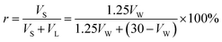
The volume of water participating in hydrate formation (VW) and the volume of hydrates (VS) can be calculated by eqn (3) and (4), respectively:
where Δ
nW is the molar amount of water participating in the reaction, Δ
nW = Δ
n × 5.75,
ML is the molar mass of water, and the hydrate volume expansion coefficient is 1.25.
22,36
The hydrate volume fraction is an important indicator for the evaluation of promoters, which is obtained by the following equation in this paper:
| |
 | (5) |
where
VL represent the volume of remaining water.
3 Results and discussion
3.1 Hydrate formation in gas-pure water systems
The formation process of gas hydrate is a non-equilibrium kinetic process, which can be divided into three stages, namely, dissolution, induction and growth stage.
The first stage is the dissolution period of methane, where methane accumulates at the gas–liquid interface and enters the liquid phase, increasing the gas concentration in the liquid phase, providing suitable conditions for the formation of hydrates.37
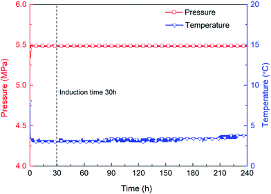
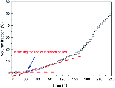
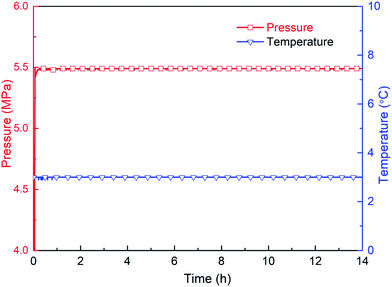
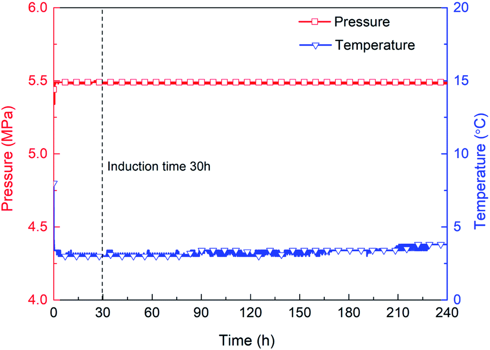
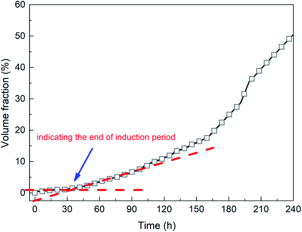
The second stage is the induction period (0–30 h), which is the preparation for the nucleation of hydrates to reach critical size. As shown in Fig. 6, pressure remains unchanged during the whole experimental process, as the piston in the reactor moves downward automatically. After finishing fast cooling of the experimental liquid, temperature also nearly remains unchanged. Fig. 7 illustrates that in the induction period, hydrate volume fraction slightly increases, due to the further increase of gas concentration in liquid phase. In other words, supersaturation may occur in the gas-pure water system. During this stage, water molecules gather around gas molecules, and hydrates will preferentially nucleate at the positions where the formation conditions are satisfied. These nucleation positions mostly locate at the gas–water interface and few on the surfaces of gas bubbles in the liquid phase. Afterwards, the network structure formed by gas molecules and water molecules breaks up and reorganize continuously.38 The nuclei finally reach critical size, after which a large amount of hydrates emerge and hydrate volume fraction increases significantly (see Fig. 7), indicating the end of induction period. The induction time of the methane–pure water system in this work is approximately 30 h. At the same time, it can be found that when hydrate formation begins, the system temperature does not change significantly (Fig. 6). Because there is no agitation, the growth of hydrates is extremely slow, the amount of liquid injection is small, and the heat generated due to hydrate formation can be taken away by the water bath system in time.
 |
| | Fig. 6 Variations of pressure and temperature with time in the pure water system. | |
 |
| | Fig. 7 Variation of methane hydrate volume fraction with time in the pure water system. | |
The third stage is the steady growth process of the crystals. The heat and mass are transferred between water, hydrate and gas phase, which is a process in which tiny hydrate crystals aggregate into larger hydrate particles finally. As shown in Fig. 7, hydrate volume fraction increases continuously to approximately 50% in 10 days.
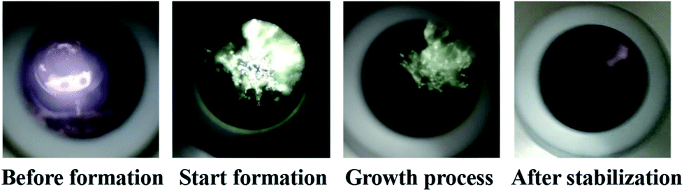
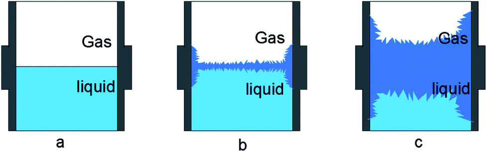
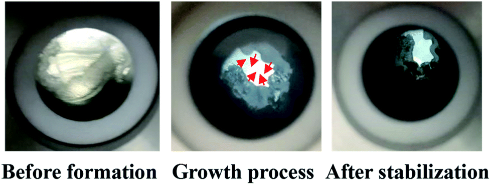
Fig. 8 shows the visual observation results during hydrate formation in the gas-pure water system. Its macroscopic conceptual diagram is shown in Fig. 9. At the end of the induction period, there is no discernible hydrate crystal in the kettle (see Fig. 9a). Hydrates firstly emerge at the gas–liquid–metal interface, where the subcooling degree as well as the gas concentration are the largest. In other words, the hydrate nucleation driving force is the largest at the gas–liquid–metal interface. After nucleation, hydrates horizontally extend to the center of the gas–liquid interface and a hydrate film forms (see Fig. 9b). Since the hydrate film prevents the contact between gas and liquid, the hydrate formation rate is pretty slow in the static pure-water system. The hydrate layer at the interface gradually grow downward the gas–water interface and finally a thick hydrate layer forms (see Fig. 9c). Therefore, for methane hydrate formation in the pure water system in this work, the induction time is relatively long and the growth rate is relatively low, which is unacceptable for the hydrate application issues and should be improved.
 |
| | Fig. 8 Snapshots of hydrate formation in the gas-pure water system. | |
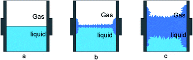 |
| | Fig. 9 Macroscopic conceptual diagram of hydrate formation (a–c). | |
3.2 Effects of hydrate promoters and their compositions on the formation characteristics of methane hydrates
How long it required for hydrates to form target amounts under different experimental conditions is the premise and basis of hydrate application, which is also one of the significant indication of hydrate promoters. Hydrate formation experiments were carried out in gas–water systems with different components of the compound promoter under the constant temperature of 3 °C, constant pressure of 5.50 MPa and mass concentration of 1000 ppm. The compound promoters compose of 1#, 2# and 3# unit promoter, and mass ratios of these units are selected as 2:1:2, 1:1:1, 1:1:2 and 2:1:1 (promoter 1#:2#:3#). The experimental results are presented in Fig. 10–13.
 |
| | Fig. 10 Variation of pressure and temperature with time in the system with ratio of 2:1:2. | |
 |
| | Fig. 11 Variation of pressure and temperature with time in the system with ratio of 1:1:1. | |
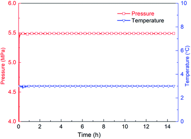
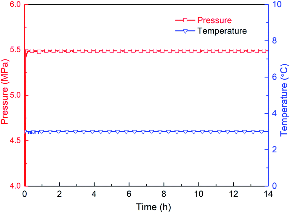
Hydrate formation is an exothermic reaction with methane consumption. Therefore, whether hydrates forms in the reactor can be judged by monitoring the magnitude of the change in temperature and pressure. Fig. 10–12 show that in the gas–water systems with the promoter proportion of 2:1:2, 1:1:1 and 1:1:2, no hydrate forms even after 15 h. Fig. 13 shows that there is significant temperature increase and pressure decrease in the 2:1:1 compounding system at 0.64 h, indicating that hydrate formation induction time is shortened to 0.64 h and a large amount of hydrate forms subsequently. The evaluation parameters, including induction time, gas consumption (15 h) and final hydrate volume fraction, under each compounding ratio are tabulated in Table 1. It can be seen that the compounding ratio 2:1:1 is the optimum ratio to promote hydrate formation among these selected ratios in this work, which is then named as TH3 and the following experiments are carried out using this optimal ratio. Compared to the pure-water system, the induction time is significantly shortened by the proper promoter, and average hydrate formation rate is extremely higher (83.652%/6.0 h ≫ 60%/240 h).
 |
| | Fig. 12 Variation of pressure and temperature with time in the system with ratio of 1:1:2. | |
 |
| | Fig. 13 Variation of pressure and temperature with time in the system with ratio of 2:1:1. | |
Table 1 Hydrate formation parameters under different component ratios
| Proportion (1#:2#:3#) |
Induction time (h) |
Gas consumption (15 h, mol) |
Hydrate volume fraction (%) |
| 2:1:2 |
>15 |
0.006412 |
0 |
| 2:1:1 |
0.64 |
0.116208 |
45.549 |
| 1:1:1 |
>15 |
0.005254 |
0 |
| 1:1:2 |
>15 |
0.006511 |
0 |
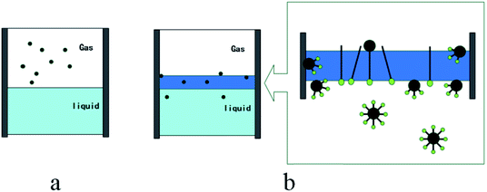
Fig. 14 is the conceptual diagram of the dissolution process of methane in the gas–water system with and without the promoter (TH3). Fig. 14a shows the dissolution process of methane gas under the condition without additives. The gas–liquid interfacial tension is not reduced. Fig. 14b indicates the surface tension of the liquid system is reduced with the function of the additives, the resistance of the gas entering the liquid phase is reduced. In the dissolution process of methane, there is a clear transition zone at gas–liquid interface, as a solubilization zone with a very low surface tension. Due to the function of the promoter, more gas can be dissolved into water and the mass transfer of gas molecules can be promoted. The promoter compounded of three types of surfactants is selectively adsorbed at the gas–liquid and liquid–solid interfaces. A molecular layer on the interface of upper gas phase and lower water phase forms, and the surface tension of the aqueous solution is reduced to the lowest point, thereby adding more nucleation sites to the gas–liquid and liquid–solid interfaces. After hydrate nucleation, the hydrate film is a needle-like loose structure, and the siphon action generated at the pores makes the gas and liquid contact more easily. Then water molecules are transported to the wall surface continuously, and consequently hydrate formation at the wall surface is promoted.39,40
 |
| | Fig. 14 Conceptual diagram of methane dissolution process (a and b). | |
Fig. 15 is the images obtained during hydrate formation process through the visual window of the autoclave. Combining Fig. 8 and 15, systems with and without the promoter show very different morphology behavior of hydrate formation. Unlike the pure water system, hydrates expand upwards and downwards at the gas–water interface. Meanwhile, hydrates spread from the metal wall to the center of the lens gradually, after which the liquid level drops, and hydrates extend downward as well as in the middle until they fill the reaction vessel to form hollow-like hydrates.
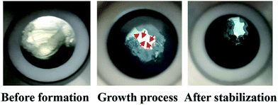 |
| | Fig. 15 Snapshots of the gas–water systems with hydrate promoter. | |
3.3 Effect of dosage on the formation characteristics of methane hydrate
The characteristics of gas hydrate formation in gas–water systems with different dosages of additive (TH3) were investigated. Methane hydrate formation experiments were conducted under the constant experimental temperature of 3 °C and constant pressure of 5.50 MPa with concentrations of 500 ppm, 1000 ppm, 2000 ppm and 5000 ppm. The formation parameters of hydrate formation (induction time and average hydrate formation rate etc.) with different dosages of TH3 are tabulated in Table 2. Fig. 16 shows the temperature profiles of the systems with different dosages of TH3. As seen, the induction time is shortened to 2.52 h, 0.64 h, 0.52 h and 0.22 h, as well as the hydrate formation rate is promoted to different extents by TH3 with different dosages (500–5000 ppm). Meanwhile, the induction time shortens with the increasing mass concentration within the experimental range, which is consistent with the results reported by Lee et al.41 When the mass concentration is selected as 5000 ppm, the hydrate formation induction time is about 0.22 h, and the induction time is shortened by 136.4 times compared to that of the system in the absence of the promoter, indicating remarkable promoting effect.
Table 2 Effect of different additional amounts on hydrate formation parameters
| Concentration (ppm) |
Induction time (h) |
Gas consumption (8 h, mol) |
Average hydrate formation rate (ml h−1) |
Hydrate volume fraction (8 h, %) |
| 500 |
2.52 |
0.078095 |
11.382 |
31.553 |
| 1000 |
0.64 |
0.116208 |
16.112 |
45.549 |
| 2000 |
0.52 |
0.117929 |
24.684 |
46.162 |
| 5000 |
0.22 |
0.106391 |
21.906 |
42.122 |
 |
| | Fig. 16 Experimental temperature of the systems with different dosages of TH3 versus time. | |
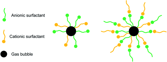
Fig. 17 shows the hydrate volume fraction of the systems with different dosages of TH3. For the system with 500 ppm promoter, the final hydrate volume fraction is significantly lower than that of the systems with higher dosages of promoter, but is still much higher than that of the system without promoter. The final hydrate volume fraction of the gas–water systems first increase and then decrease with the increasing TH3 mass concentration. The highest final hydrate volume fraction is obtained in the presence of 2000 ppm TH3. It is supposed that after adding a smaller amount of the promoter, the gas molecules can be surrounded by the hydrophobic group of the promoter.42 As shown in Fig. 18, with the function of the hydrophilic group, the micelles (one-layer structure) are uniformly distributed in the aqueous phase, which promotes the dissolution of the gas into the liquid phase. The concentration difference of gas molecules in hydrate phase and water phase provides the driving force for hydrate formation.44 However, when the concentration of the added promoter is too high, the attaching point of the bubble surface is gradually filled. Since the promoter is the mixture of three types of surfactants, including anionic and cationic surfactant, it is speculated that the electric charge of the hydrophilic group of one excess promoter molecule is opposite to that of another molecule43 which is adsorbed on the surface of gas bubble, and consequently they are attracted to each other (see Fig. 18). Therefore, the mass transfer of water molecules into the surfaces of gas bubbles is hindered, resulting in a reduction in gas consumption and hydrate volume fraction.44 In order to more intuitively compare the effect of different additions on the gas consumption rate of hydrate, average formation rate45 is used in this work, which is defined as the ratio of the volume of hydrate produced during a certain period to the time and in units of ml h−1.
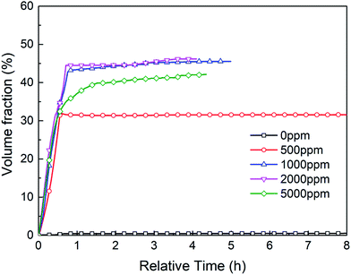 |
| | Fig. 17 Hydrate volume fraction of the systems with different dosages of TH3 versus relative time. | |
 |
| | Fig. 18 Conceptual diagram of one-layer and two-layer group encasing gas molecules. | |
Table 2 shows that average hydrate formation rate has the similar variation trend with hydrate volume fraction, as the promoter dosage increases. This also indicates that the promoter exists a optimal dosage. These findings are consistent with Yang et al.46 and Li et al.47 using SDS and SDBS as promoters. Traditional surfactant SDS were also used to carry out some experiments in this work. And results are compared with that of TH3 and that of SDS conducted by other researcher48,49 using different reactors. As shown in Table 3, it is found that TH3 has significant advantages in shortening the induction time, which may be the coordination of multiple unit promoters after compounding.43 To further understand the effects of additives on the characteristics of hydrate formation, subsequent work should be conducted with other experimental conditions.
Table 3 Kinetic parameters of methane hydrate under different conditions
| Promoter type |
Pressure (MPa) |
Temperature (°C) |
Concentration (ppm) |
Injection volume (ml) |
Induction time (min) |
Average gas consumption (mol min−1) |
| TH3 (this work) |
5.5 |
3.0 |
1000 |
30 |
26 |
0.00211 |
| SDS (this work) |
6.0 |
3.0 |
300 |
30 |
40 |
0.00306 |
| SDS (this work) |
7.5 |
3.0 |
1000 |
30 |
15 |
0.00618 |
| SDS48 |
6.6 |
3.25 |
800 |
10 |
— |
0.00700 |
| SDS49 |
7.0 |
0.85 |
1150 |
150 |
99.6 |
0.01627 |
3.4 Effect of subcooling degrees on the formation characteristics of methane hydrate
Subcooling degree refers to the difference between the system temperature and the equilibrium temperature of hydrate phase. It is a fundamental parameter for evaluating the kinetic promoter. The characteristics of hydrate formation in the systems with different subcoolings were investigated. The experimental pressure was 5.50 MPa, and the dosage of the promoter was 1000 ppm. Other experimental conditions and formation parameters are tabulated in Table 4.
Table 4 Effect of different subcooling degrees on hydrate formation parameters
| Subcooling (°C) |
Maximum temperature difference (°C) |
Induction time (h) |
Gas consumption (8 h, mol) |
Average hydrate production rate (ml h−1) |
Hydrate volume fraction (8 h, %) |
| 2.5 |
2.2 |
3.99 |
0.119890 |
12.904 |
46.857 |
| 3.5 |
3.3 |
0.80 |
0.122241 |
13.099 |
47.799 |
| 4.5 |
4.0 |
0.64 |
0.116208 |
16.122 |
45.549 |
| 5.5 |
5.2 |
0.37 |
0.107336 |
31.866 |
42.367 |
| 6.5 |
5.4 |
0.29 |
0.094167 |
32.196 |
37.526 |
It has been reported that, for one-component gas hydrates, the hydrate nucleation driving force generally depends on either the subcooling degree and/or the over-pressurizing level of the system against the equilibrium state.50 Therefore, in this work, the effect of experimental temperature on hydrate induction time can be investigated under the constant pressure condition. Fig. 19 displays the changes of temperature during methane hydrate formation process under different subcooling degrees. As obviously seen, with the increasing subcooling degree, the temperature-peak curve of different systems is larger and narrower, indicating faster hydrate formation, which is similar to the phenomenon observed in DSC systems.51 Fig. 20 shows that induction time decreases as the subcooling degree increases, which is ascribable to higher crystallization driving force and lower free energy of the system52 with decreasing experimental temperature.
 |
| | Fig. 19 Temperature of the systems with different subcooling degrees versus time. | |
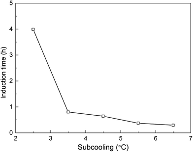 |
| | Fig. 20 Hydrate induction time versus subcooling degree. | |
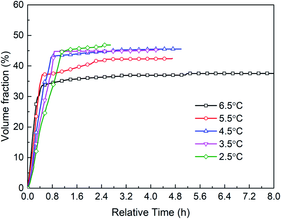
Fig. 21 shows the hydrate volume fraction of the systems under different subcooling degrees. It is found that the gas consumption and the final hydrate volume fraction first increase and then decrease with the increasing subcooling degree (see Table 4). Specifically, when the subcooling degree of the system approaches 6.5 °C, the gas consumption is significantly reduced, and final hydrate volume fraction of the system with 6.5 °C subcooling is only 78.5% of the system with 3.5 °C subcooling. Moreover, as shown in Fig. 21, at the initial stage of hydrate formation (0–0.3 h, relative time), hydrate formation rate, which is proportional to the slope of the curve, increases with the increasing subcooling degree,53 i.e., rini(2.5 °C) (refers to the initial formation rate of the system with 2.5 °C subcooling) < rini(3.5 °C) < rini(4.5 °C) < rini(5.5 °C) < rini(6.5 °C). However, final hydrate volume fraction exhibits the opposite trend, i.e., Ffin(2.5 °C) (refers to the final hydrate volume fraction of the system with 2.5 °C subcooling) > Ffin(3.5 °C) > Ffin(4.5 °C) > Ffin(5.5 °C) >Ffin(6.5 °C). These phenomena are predominately caused by thicker hydrate layer formed under higher subcooling due to the lack of stirring in the reactor. It was found than hydrates tend to nucleate at the water–hydrate interface and form a dense hydrate layer,54 which hinders gas–liquid contact. In this work, under higher subcooling degrees and larger formation driving force, after hydrates first nucleate at the gas–liquid interface, hydrate formation rate is higher at the beginning, and a thicker hydrate layer forms at the interface. Thereafter, the thicker layer blocks the contact of methane gas with aqueous solution and hinders further hydrate formation more easily,9,54 finally resulting in smaller amount of hydrate formation. On the other hand, the solubility or activity of the promoter may also be affected by temperature.55,56 Further experimental studies should be conducted under the conditions with stirring or other temperature range (such as freezing point) to verify the effect.
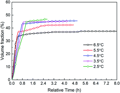 |
| | Fig. 21 Hydrate volume fraction of the systems under different subcooling degrees versus relative time. | |
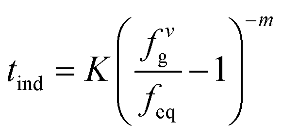
3.5 Induction time model for the gas–water systems with promoter addition
Hydrate formation can be divided into two stages: nucleation and growth stage, the induction period begins after the gas phase dissolves in the water phase and ends before the continuous growth of hydrate crystals. Natarajan et al.57 developed an induction time model to predict the induction time of natural gas hydrate in gas-pure water system. The hydrate formation experimental conditions and the fugacity difference (fvg − feq) under phase equilibrium conditions were used as the hydrate formation driving force, and the hydrate nucleation rate in pure water was expressed as follows:| |
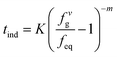 | (6) |
where K and m are experimentally-adjusted parameters, describes nucleation characteristics. The R–K equation of state35 is used to calculate the fugacity of gas under various conditions (the calculation results are shown in Table 5), and equilibrium conditions of natural gas hydrate were experimentally measured.
Table 5 Compressor factor and fugacity data for methane gas under experimental conditions
| Pressure/Pa |
Temperature/K |
Compressor factor |
fg (Pa−1) |
| 5500000 |
274.15 |
0.86997 |
4808146.161 |
| 5500000 |
275.15 |
0.87265 |
4827727.222 |
| 5500000 |
276.15 |
0.87419 |
4825584.004 |
| 5500000 |
277.15 |
0.87614 |
4835718.373 |
| 5500000 |
278.15 |
0.87698 |
4843777.684 |
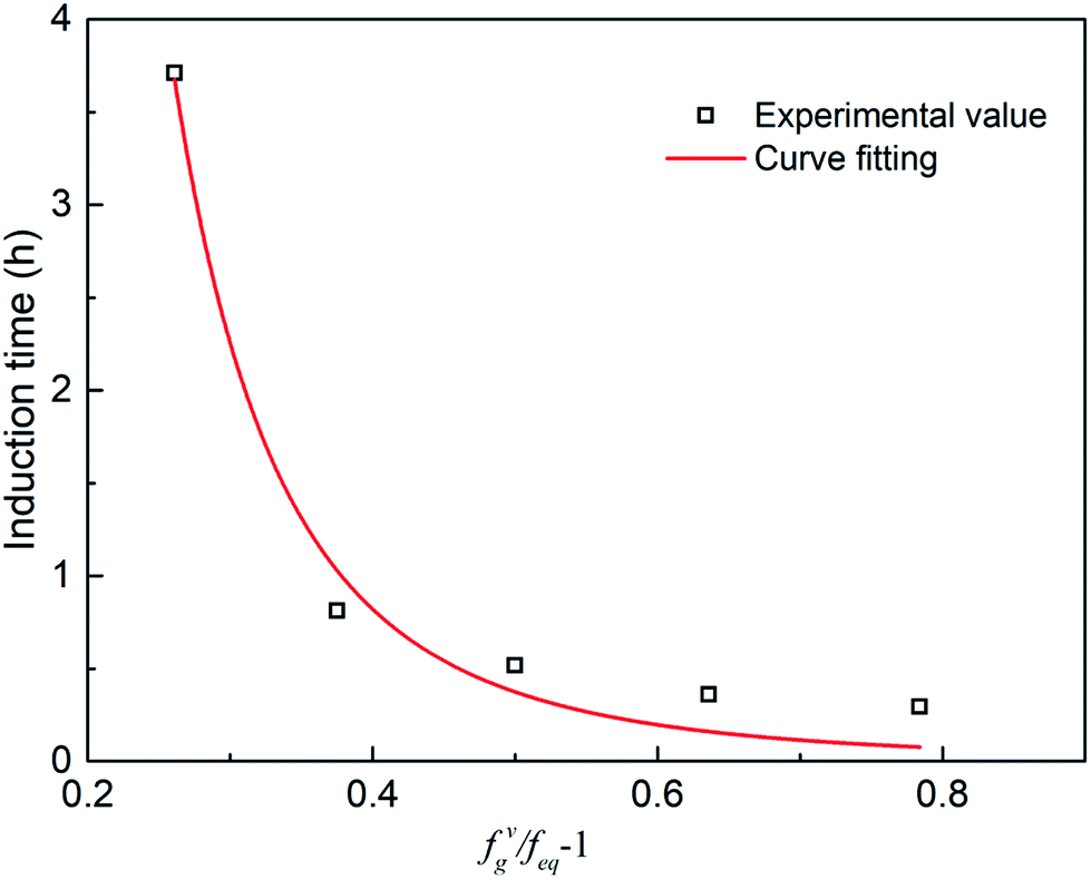
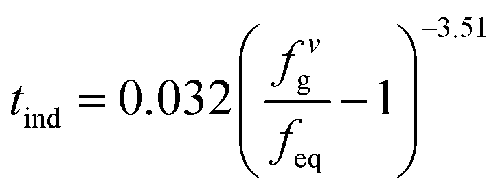
The parameters in eqn (6) were determined by experimental data regression to obtain the induction time model 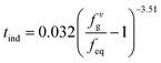 with the optimal additive amount (1000 ppm). The fitting curve is obtained from the experimental data, as shown in Fig. 22. As seen, the model can well predict hydrate formation induction time in the presence of the promoter.
 |
| | Fig. 22 Induction time prediction value and experimental value. | |
4 Conclusion
(1) The new kinetic promoter was obtained by compounding 1#, 2# and 3# unit promoter in a ratio of 2:1:1. The promotion effect on methane hydrate formation was significant: compared with the scenario in the absence of the promoter, the induction time was shortened from 30 h to 0.64 h, and the average generation rate was boosted to 16.112 ml h−1, and the hydrate volume fraction changed from 50% (growth duration of appro. 240 h) to 45.549% (growth duration of appro. 8 h).
(2) The performance test for the new promoter showed that the induction time decreased with the increasing dosage of the promoter. Under the experimental temperature of 3 °C and the pressure of 5.50 MPa, when the dosage of additives was 5000 ppm, the hydrate formation induction time was the shortest, only 0.22 h. However, the hydrate formation rate and final hydrate volume fraction reduced with the increasing dosage of the promoter, when more than 2000 ppm promoter was added. Thus, 2000 ppm was regarded as the optimal dosage in this work (the induction time was shortened to 0.52 h, the final hydrate formation volume fraction was 46.16% (8 h), and the average generation rate was 24.68 ml h−1).
(3) The subcooling degree of the systems with the presence of TH3 has a significant effect on the induction time, gas consumption and average hydrate formation rate. As a driving force for hydrate formation, the higher the subcooling degree, the faster the nucleation rate of hydrate, the shorter the induction time. However, according to the experimental data, in the systems with pressure of 5.50 MPa and promoter dosage of 1000 ppm, when the subcooling degree exceeds 3.5 °C and continues increasing, the hydrate layer is rapidly formed at the gas–liquid interface due to the increase of the driving force, which hinders the gas–liquid contact, resulting in smaller amount of hydrate formation. Therefore, in the reactor without stirring, the experimental temperature should be reasonably selected to promote the formation of hydrate. At the same time, the hydrate induction time model under this condition is obtained which shows good predicting accuracy.
Conflicts of interest
There are no conflicts of interest to declare.
Acknowledgements
This work was supported by the National Natural Science Foundation of China (Grant No. 51804046 & 51904330& 51974037), PetroChina Innovation Foundation (Grant No. 2018D-5007-0602) and Natural Science Research Project of Jiangsu Colleges and Universities (Grant No. 18KJB440001).
References
- Y. Song, L. Yang and J. Zhao, et al., The status of natural gas hydrate research in China: a review, Renewable Sustainable Energy Rev., 2014, 31, 778–791 CrossRef CAS.
- C. A. Koh, A. K. Sum and E. D. Sloan, State of the art: natural gas hydrates as a natural resource, J. Nat. Gas Sci. Eng., 2012, 8, 132–138 CrossRef.
- C. Moisescu, C. Jana and S. Habelitz, et al., Oriented fluoroapatite glass-ceramics, J. Non-Cryst. Solids, 1999, 248(2–3), 176–182 CrossRef CAS.
- A. A. Khokhar, J. Gudmundsson and E. D. Sloan, Gas storage in structure H hydrates, Fluid Phase Equilib., 1998, 150, 383–392 CrossRef.
- H. P. Veluswamy, R. Kumar and P. Linga, Hydrogen storage in clathrate hydrates: current state of the art and future directions, Appl. Energy, 2014, 122, 112–132 CrossRef CAS.
- V. V. Struzhkin, B. Militzer and W. L. Mao, et al., Hydrogen storage in molecular clathrates, Chem. Rev., 2007, 107(10), 4133–4151 CrossRef CAS.
- L. C. Elwell and W.S. Grant, et al., Technology options for capturing CO2, Electric Power Construction, 2007, 149(8), 62–65 Search PubMed.
- R. J. Allam, R. Bredesen and E. Drioli, Carbon Dioxide Separation Technologies, Carbon Dioxide Recovery and Utilization, 2003 Search PubMed.
- L. Cai, B. A. Pethica and P. G. Debenedetti, et al., Formation kinetics of cyclopentane–methane binary clathrate hydrate, Chem. Eng. Sci., 2014, 119, 147–157 CrossRef CAS.
- K. C. Kang, P. Linga and K. N. Park, et al., Seawater desalination by gas hydrate process and removal characteristics of dissolved ions (Na+, K+, Mg2+, Ca2+, B3+, Cl-, SO42-), Desalination, 2014, 353, 84–90 CrossRef CAS.
- X. Wang, M. Dennis and L. Hou, Clathrate hydrate technology for cold storage in air conditioning systems, Renewable Sustainable Energy Rev., 2014, 36, 34–51 CrossRef CAS.
- P. Zhang and Z. W. Ma, An overview of fundamental studies and applications of phase change material slurries to secondary loop refrigeration and air conditioning systems, Renewable Sustainable Energy Rev., 2012, 16(7), 5021–5058 CrossRef CAS.
- A. A. Khokhar, J. S. Gudmundsson and E. D. Sloan, Gas storage in structure H hydrates, Fluid Phase Equilib., 1998, 150, 383–392 CrossRef.
- U. K. And and M. Parlaktuna, Surfactants as Hydrate Promoters, Energy Fuels, 2000, 14(5), 1103–1107 CrossRef.
- Y. Zhong and R. E. Rogers, Surfactant effects on gas hydrate formation, Chem. Eng. Sci., 2000, 55(19), 4175–4187 CrossRef CAS.
- J. Verrett, D. Posteraro and P. Servio, Surfactant effects on methane solubility and mole fraction during hydrate growth, Chem. Eng. Sci., 2012, 84, 80–84 CrossRef CAS.
- I. Watanabek and Y. H. Mori, Surfactant effects on hydrate formation in an unstirred gas/liquid system: an experimental study using HFC-32 and sodium dodecyl sulfate, Chem. Eng. Sci., 2015, 60(5), 4846–4857 Search PubMed.
- H. Kakati, A. Mandal and S. Laik, Promoting effect of Al2O3/ZnO-based nanofluids stabilized by SDS surfactant on CH4 + C2H6 + C3H8 hydrate formation, J. Ind. Eng. Chem., 2016,(35), 357–368 CrossRef CAS.
- Z. Sun, R. Wang and R. Ma, Natural gas storage in hydrates with the presence of promoters, Energy Convers. Manage., 2003, 44(17), 2733–2742 CrossRef CAS.
- V. K. Saw, M. Gudala and G. Udayabhanu, et al., Kinetics of methane hydrate formation and its dissociation in presence of non-ionic surfactant Tergitol, Journal of Unconventional Oil and Gas Resources, 2014, 6, 54–59 CrossRef.
- H. Kakati, A. Mandai and S. Laik, Phase Stability and Kinetics of CH4 + CO2 + N2 Hydrates in Synthetic Seawater and Aqueous Electrolyte Solutions of NaCI and CaCl2, J. Chem. Eng. Data, 2015, 60(6), 1835–1843 CrossRef CAS.
- H. P. Veluswamy, S. Kumar, R. Kumar, P. Rangsunvigit and P. Linga, Enhanced clathrate hydrate formation kinetics at near ambient temperatures and moderate pressures: application to natural gas storage, Fuel, 2016, 182, 907–919 CrossRef CAS.
- J. S. Zhang, S. Y. Lee and J. W. Lee, et al., Kinetics of methane hydrate formation from SDS solution, Ind. Eng. Chem. Res., 2007, 46(19), 6353–6359 CrossRef CAS.
- A. Kumar and A. Kumar, Role of metallic packing and kinetic promoter in designing a hydrate-based gas separation process, Energy Fuels, 2015, 29(7), 4463–4472 CrossRef CAS.
- K. Okutani, Y. Kuwabara and Y. H. Mori, Surfactant effects on hydrate formation in an unstirred gas/liquid system: an experimental study using methane and sodium alkyl sulfates, Chem. Eng. Sci., 2008, 63(1), 183–194 CrossRef CAS.
- L. Jiang, A. Li and J. Xu, et al., Effects of SDS and SDBS on CO2 hydrate formation, induction time, storage capacity and stability at 274.15 K and 5.0 MPa, ChemistrySelect, 2016, 1(19), 6111–6114 CrossRef CAS.
- J.-P. Torre, M. Ricaurte, C. Dicharry and D. Broseta, CO2 enclathration in the presence of water-soluble hydrate promoters: hydrate phase equilibria and kinetic studies in quiescent conditions, Chem. Eng. Sci., 2012, 82, 1–13 CrossRef CAS.
- C. F. d. S. Lirio, F. L. P. Pessoa and A. M. C. Uller, Storage capacity of carbon dioxide hydrates in the presence of sodium dodecyl sulfate (SDS) and tetrahydrofuran (THF), Chem. Eng. Sci., 2013, 96, 118–123 CrossRef.
- A. Kumar, T. Sakpal, P. Linga and R. Kumar, Influence of contact medium and surfactants on carbon dioxide clathrate hydrate kinetics, Fuel, 2013, 105, 664–671 CrossRef CAS.
- A. Mohammadi, M. Manteghian and A. Haghtalab, et al., Kinetic study of carbon dioxide hydrate formation in presence of silver nanoparticles and SDS, Chem. Eng. J., 2014, 237(1), 387–395 CrossRef CAS.
- A. Mohammadi, Semicompletion time of carbon dioxide uptake in the process of gas hydrate formation in presence and absence of SDS and silver nanoparticles, Pet. Sci. Technol., 2017, 35(1), 37–44 CrossRef CAS.
- A. Fazlali, S. A. Kazemi and M. Keshavarz-Moraveji, et al., Impact of Different Surfactants and their Mixtures on Methane-Hydrate Formation, Energy Technol., 2013, 1(8), 471–477 CrossRef CAS.
- R. E. Rogers and Y. Zhong, Feasibility of storing natural gas in hydrates commercially, Ann. N. Y. Acad. Sci., 2000, 912(1), 843–850 CrossRef CAS.
- Y. X. Pan, D. P. Liu and W. X. Huang, et al., Induction time of gas hydrate formation and its influencing factors, Nat. Gas Geosci., 2005, 16(2), 255–260 Search PubMed.
- O. Redlich and J. N. S. Kwong, On the Thermodynamics of Solutions. V. An Equation of State. Fugacities of Gaseous Solutions, Chem. Rev., 1949, 44(1), 233 CrossRef CAS.
- J. Zhang and J. W. Lee, Enhanced Kinetics of CO2 Hydrate Formation under Static Conditions, Ind. Eng. Chem. Res., 2009, 48(13), 5934–5942 CrossRef CAS.
- P. Skovborg and H. J. Ng, et al., Measurement of induction times for the formation of methane and ethane gas hydrates, Chem. Eng. Sci., 1993, 48(3), 445–453 CrossRef CAS.
- R. L. Christiansen and E. D. Sloan, Mechanisms and kinetics of hydrate formation, Ann. N. Y. Acad. Sci., 1994, 715(1), 283–305 CrossRef CAS.
- H. P. Veluswamy, J. Y. Chen and P. Linga, Surfactant effect on the kinetics of mixed hydrogen/propane hydrate formation for hydrogen storage as clathrates, Chem. Eng. Sci., 2015, 126(4), 488–499 CrossRef CAS.
- J. Yoslim, P. Linga and P. Englezos, Enhanced growth of methane-propane clathrate hydrate crystals with sodium dodecyl sulfate, sodium tetradecyl sulfate, and sodium hexadecyl sulfate surfactants, J. Cryst. Growth, 2010, 313(1), 68–80 CrossRef CAS.
- K. Lee, S. H. Lee and W. Lee, Stochastic nature of carbon dioxide hydrate induction times in Na montmorillonite and marine sediment suspensions, Int. J. Greenhouse Gas Control, 2013, 14(2), 15–24 CrossRef CAS.
- A. Mandal and S. Laik, Effect of the Promoter on Gas Hydrate Formation and Dissociation, Energy Fuels, 2008, 22(4), 2527–2532 CrossRef CAS.
- A. N. Malik, Surfactant-Amino Acid and Surfactant-Surfactant Interactions in Aqueous Medium: A Review, Appl. Biochem. Biotechnol., 2015, 176(8), 2077–2106 CrossRef.
- C. Y. Sun, G. J. Chen and C. F. Ma, et al., The growth kinetics of hydrate film on the surface of gas bubble suspended in water or aqueous surfactant solution, J. Cryst. Growth, 2007, 306(2), 491–499 CrossRef CAS.
- Y. Chen, B. Shi and Y. Liu, et al., Experimental and Theoretical Investigation of the Interaction between Hydrate Formation and Wax Precipitation in Water-in-Oil Emulsions, Energy Fuels, 2018, 32(9), 9081–9092 CrossRef CAS.
- M. Yang, Y. Song and W. Liu, et al., Effects of additive mixtures (THF/SDS) on carbon dioxide hydrate formation and dissociation in porous media, Chem. Eng. Sci., 2013, 90, 69–76 CrossRef CAS.
- Y. X. Li, C. Zhu and W. C. Wang, Promoting Effects of Surfactants on Carbon Dioxide Hydrate Formation and the Kinetics, Petrochem. Technol., 2012, 41(6), 699–703 CAS.
- W. Lin, G. J. Chen and C. Y. Sun, et al., Effect of surfactant on the formation and dissociation kinetic behavior of methane hydrate, Chem. Eng. Sci., 2004, 59(21), 4449–4455 CrossRef CAS.
- J. S. Zhang, S. Lee and J. W. Lee, Kinetics of Methane Hydrate Formation from SDS Solution, Ind. Eng. Chem. Res., 2007, 46(19), 6353–6359 CrossRef CAS.
- M. Arjmandi, B. Tohidi and A. Danesh, et al., Is subcooling the right driving force for testing low-dosage hydrate inhibitors, Chem. Eng. Sci., 2005, 60(5), 1313–1321 CrossRef CAS.
- J. W. Lachance, E. D. Sloan and C. A. Koh, Determining gas hydrate kinetic inhibitor effectiveness using emulsions, Chem. Eng. Sci., 2009, 64(1), 180–184 CrossRef CAS.
- X. S. Li, C. G. Xu, Z. Y. Chen and H. J. Wu, Tetra-n-butyl Ammonium Bromide Semi-Clathrate Hydrate Process for Post-Combustion Capture of Carbon Dioxide in the Presence of Dodecyl Trimethyl Ammonium Chloride, Energy, 2010, 35(9), 3902–3908 CrossRef CAS.
- S. P. Kang and J. W. Lee, Kinetic behaviors of CO2 hydrates in porous media and effect of kinetic promoter on the formation kinetics, Chem. Eng. Sci., 2010, 65(5), 1840–1845 CrossRef CAS.
- T. Uchida, T. Ebinuma and J. Kawabata, et al., Microscopic observations of formation processes of clathrate-hydrate films at an interface between water and carbon dioxide, J. Cryst. Growth, 1999, 204(3), 348–356 CrossRef CAS.
- M. J. Yang, Y. C. Song and W. G. Liu, et al., Effects of additive mixtures(THF/SDS) on carbon dioxide hydrate formation and dissociation in porous media, Chem. Eng. Sci., 2013, 90, 69–76 CrossRef CAS.
- C. Dicharry, J. Diaz and J. P. Torré, et al., Influence of the carbon chain length of a sulfate-based surfactant on the formation of CO2, CH4 and CO2–CH4 gas hydrates, Chem. Eng. Sci., 2016, 152, 736–745 CrossRef CAS.
- V. Natarajan, P. R. Bishnoi and N. Kalogerakis, Induction phenomena in gas hydrate nucleation, Chem. Eng. Sci., 1994, 49(13), 2075–2087 CrossRef CAS.
|
| This journal is © The Royal Society of Chemistry 2019 |
Click here to see how this site uses Cookies. View our privacy policy here. 
 Open Access Article
 This Open Access Article is licensed under a Creative Commons Attribution-Non Commercial 3.0 Unported Licence
 *a,
Dayong Lua,
Yang Liu
*a,
Dayong Lua,
Yang Liu


 with the optimal additive amount (1000 ppm). The fitting curve is obtained from the experimental data, as shown in Fig. 22. As seen, the model can well predict hydrate formation induction time in the presence of the promoter.