
 Open Access Article
 This Open Access Article is licensed under a Creative Commons Attribution-Non Commercial 3.0 Unported Licence
Facile one-pot synthesis of NiCo2Se4-rGO on Ni foam for high performance hybrid supercapacitors†
Bahareh Golrokh Amin ,
Jahangir Masud and
Manashi Nath*
,
Jahangir Masud and
Manashi Nath*
Department of Chemistry, Missouri University of Science and Technology, USA. E-mail: nathm@mst.edu
First published on 21st November 2019
Abstract
A facile, innovative synthesis for the fabrication of NiCo2Se4-rGO on a Ni foam nanocomposite via a simple hydrothermal reaction is proposed. The as-prepared NiCo2Se4-rGO@Ni foam electrode was tested through pxrd, TEM, SEM, and EDS to characterize the morphology and the purity of the material. The bimetallic electrode exhibited outstanding electrochemical performance with a high specific capacitance of 2038.55 F g−1 at 1 A g−1. NiCo2Se4-rGO@Ni foam exhibits an extensive cycling stability after 1000 cycles by retaining 90% of its initial capacity. A superior energy density of 67.01 W h kg−1 along with a high power density of 903.61 W kg−1 further proved the high performance of this electrode towards hybrid supercapacitors. The excellent electrochemical performance of NiCo2Se4-rGO@Ni foam can be explained through the high electrocatalytic activity of NiCo2Se4 in combination with reduced graphene oxide which increases conductivity and surface area of the electrode. This study proved that NiCo2Se4-rGO@Ni foam can be utilized as a high energy density-high power density electrode in energy storage applications.
Introduction
The rapidly increasing global demand for an alternative, renewable energy system encouraged researchers to explore high-performance energy storage technologies to store the energy harnessed from eco-friendly sources.1–4 Numerous endeavors were made to elevate performance of the dominant energy storage technology, namely, batteries, particularly Li-ion batteries which have shown significant progress over the last several decades.5,6 However, regardless of the high energy density that batteries can provide, they are still not fulfilling all our energy storage demands since they suffer from low power density, slow charge–discharge rate, and limited cycle life. Gradual degradation of the batteries in storing and delivering energy throughout their lifetime can be attributed to their deficiencies in undergoing a fully reversible redox reaction during repetitive charge–discharge process.7–10Electrochemical supercapacitors have been introduced to bridge the gap between electrolytic capacitors (with high power density and low energy density) and rechargeable batteries (with high energy density and low power density). Supercapacitors are known as one of the most promising energy storage devices owing to their high specific capacitance, promising power density, short charge–discharge time, longer lifespan, and being safer to use compared to batteries.11–14 Contrary to Li-ion battery technology, supercapacitors, operate over wider temperature ranges due to their simpler electrochemical mechanism of storing charge. This results in lower thermo-chemical heat, consequently, making these devices safer to store energy.5
The supercapacitors can be classified into three categories based on their charge storage mechanism and use of active electrode materials: (i) electrochemical double layer capacitor (EDLC) which stores charge in highly porous or high surface area electrodes such as carbon-based materials including graphene, CNTs etc.;15–17 (ii) pseudocapacitors, also known as redox supercapacitors, which stores charge through reversible electrochemical redox reactions using the variable oxidation states of transition metal based centers in the corresponding oxides,18–21 hydroxides,21–24 chalcogenides25–28 as electrode materials; (iii) hybrid electrochemical capacitor which are a combination of both EDLCs and pseudocapacitors and incorporate redox-active transition metal-based centers onto high surface area, porous electrodes.29–32
EDLCs store charge electrostatically via generation of electrical double layer in the non-faradaic region at the interface between electrode and electrolyte. Hence, without diffusion limitations, the response to changes in potential is fast and leads to high power density.29 Recently, graphene, a 2-dimensional sheet of hexagonally bonded network of carbon atoms, has been used as the electrode material for EDLCs due to its extraordinary high electrical and thermal properties along the basal plane.33,34 However, due to the low specific capacitance of EDLCs, they are unable to replace Li-ion batteries, as they cannot provide the energy density necessary for practical applications.33,35 On the other hand, reversible electrochemical redox reactions occurring within the inner surface of electroactive materials or at the electrode–electrolyte interface is the primary charge storage mechanism of a pseudocapacitor.36,37 The overall performance of the supercapacitors can be further boosted by combining the non-faradaic process of EDLCs with the faradaic process of pseudocapacitors thereby leading to hybrid supercapacitors. Accordingly, the hybrid supercapacitor shows higher capacitance with improved energy and power density than either EDLCs or pseudocapacitors.38–41 As mentioned above, the electrochemical performance of supercapacitors is mainly related to the electrode materials and their properties. Therefore, extensive research has been done to fabricate new electrode composites for application in energy storage devices.
Recently, transition metal-based compounds have been widely investigated in several electrochemical applications such as full water splitting,42–45 non-enzymatic glucose sensing,46,47 and supercapacitors48–50 due to their abundance, cost-effectiveness, good electrical conductivity, excellent electrocatalytic activity and more importantly redox tunability. Very recently, transition metal chalcogenides (TMCs), in particular, selenide-based compounds have been extensively investigated as potential electrocatalysts in energy conversion devices, wherein, their electrocatalytic performance was significantly improved owing to the tunable redox properties of the active transition metal catalytic center. Moreover, the small bandgap and high degree of covalency of selenide-based compounds enhances charge transport properties which promotes better electrical conductivity, making them significantly better electrochemical active sites compared to their respective oxide analogues.46,51,52
Among several types of TMCs, Ni- and Co-based selenides are favorable as pseudocapacitor electrode materials due to their desirable electrochemical activity in alkaline electrolytes arising from the tunability of the Ni2+/Ni3+ and Co2+/Co3+ redox potentials by varying anion coordination and doping. Mixed metal selenides containing both Ni and Co have also shown improvement in electrochemical activity compared to the binary selenides. In this article we have focused on a mixed metal selenide, specifically NiCo2Se4, which crystallizes in a spinel structure type where divalent Ni occupies the tetrahedral sites whereas, trivalent Co occupies the vacancy ordered octahedral layers. Such structure type offers numerous pathways for possible charge transport through metal d-band formation, effectively reducing the charge transport path length and increasing the electrochemically active area exposed to electrolyte.53–55
The high surface area along with improved electrical conductivity and good electrochemical stability of the reduced graphene oxide (rGO) in combination with nanostructured TMCs on a conductive substrate can further enhance the supercapacitive property of the nanocomposite through synergistic effects. Therefore, in this article we have reported for the first time supercapacitor performance of NiCo2Se4-rGO nanocomposite on Ni foam synthesized by a one-step hydrothermal method. The NiCo2Se4-rGO on Ni foam electrode showed high specific capacitance of 2038.55 F g−1 at 1 A g−1 with excellent energy density of 67.01 W h kg−1 and power density of 903.61 W kg−1 and good cycling stability that retains more than 90% of its maximum capacity after 1000 cycles.
Experimental
Preparation of the Ni foam substrate
Prior to deposition, the Ni foam was immersed into a solution of diluted HCl and was sonicated for 15 minutes. Then, the Ni foam was rinsed with deionized (DI) water several times and dried in an oven at 60 °C for 10 minutes.Preparation of graphene oxide (GO)
Graphene oxide (GO) was first prepared by a modified Hummers' method using natural graphite, following a procedure that has been reported in detail in our previous publication.46Synthesis of NiCo2Se4-rGO on Ni foam (NiCo2Se4-rGO@NF)
NiSO4 was purchased from Alfa Aesar, CoSO4 was purchased from Mallinckrodt, and SeO2 was purchased from Acros Organics. All chemicals were of analytical grade and used directly without further purification. Fig. 1 shows a schematic of the synthesis process of NiCo2Se4-rGO via one-step hydrothermal method of growing material directly on the Ni foam substrate without the need of a binder. First, 10 mM NiSO4 along with 25 mM of CoSO4 and 45 mM of SeO2 were dissolved and mixed in a solution of ethanol (2 ml) and DI water (8 ml) under vigorous stirring to form a homogeneous solution. Then, 0.05 g of freshly prepared graphene oxide was added to the mixture and stirred for 15 minutes. Afterwards, hydrazine hydrate (5 drops) was added to the solution, and pre-cleaned Ni foam was placed inside the vial and stirred for about 30 minutes. Later, the mixture along with the Ni foam was transferred into a Teflon-lined stainless-steel autoclave and heated in an oven at 145 °C for 8 h. The autoclave was then naturally cooled down to the room temperature overnight. The prepared electrode (NiCo2Se4-rGO@NF) was rinsed several times with DI water, and then dried at 60 °C for about 12 h. Finally, the ingrown NiCo2Se4-rGO on the surface of Ni foam electrode was subjected to thermal annealing in the presence of rapid flow of N2 gas in a closed flask at 300 °C for 2 minutes.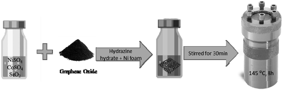 | ||
| Fig. 1 Scheme showing preparation of NiCo2Se4-rGO@Ni foam. | ||
Synthesis of NiCo2Se4 on Ni foam (NiCo2Se4@NF)
Similar synthesis method as described above carried out in the absence of GO in the reaction mixture led to the formation of NiCo2Se4 on the Ni foam substrate. Electrochemical performance of NiCo2Se4@NF was measured separately and compared with that of NiCo2Se4-rGO@NF to understand the effect of rGO on the electrochemical activity.Materials characterization
Electrochemical measurements
The electrochemical measurements, including electrochemical impedance spectroscopy (EIS), cyclic voltammetry (CV), and galvanostatic charge–discharge was measured using an IviumStat potentiostat. A typical mass loading of 0.83 mg was used for each active material composite on the anode, while the area of the Ni foam was maintained to be 1 cm2. All electrochemical measurements were performed at 25 °C in 1 M KOH aqueous solution with different current densities of 1, 2, 3, 5, 6, 8 and 10 A g−1. A three-electrode setup was used for all electrochemical measurements, where the NiCo2Se4 and NiCo2Se4-rGO modified Ni foam was used as anode, while Ni foam was used as the cathode with Ag|AgCl as reference electrode. Although the capacitance measured and reported in this article refers to the asymmetric capacitance of the anodic half-cell, the performance of a full cell was also measured using NiCo2Se4-rGO as both cathode and anode as shown in ESI (Fig. S6).†The specific capacitance of the electrode was calculated from the galvanostatic discharge curves according to the following equation: (eqn (1))5,14,19:
 | (1) |
 | (2) |
 | (3) |
Results and discussion
The crystalline phase of NiCo2Se4-rGO powder was characterized using powder X-ray diffraction (pxrd) technique. As shown in Fig. 2(a), pxrd pattern confirmed the formation of pure crystalline phase of NiCo2Se4-rGO where the diffraction peaks matched well with the reported standard pattern of Ni Co2Se4 (PDF no. 04-006-5241). The chemical composition of as-synthesized NiCo2Se4 powder without rGO was also analyzed and has been provided in the ESI (Fig. S1),† where all the diffraction peaks taken from the as-prepared powder can be indexed to the standard PDF card for NiCo2Se4 (PDF no. 04-006-5241). Similarity of the pxrd patterns of NiCo2Se4 powder with and without rGO indicated that the presence of rGO did not have any significant impact on formation of the crystalline phase and purity of the material. TEM analysis confirmed nanostructure morphology of NiCo2Se4-rGO and NiCo2Se4 as has been shown in Fig. 2(b) and S2(a),† respectively. It can be seen that the NiCo2Se4 particles were randomly distributed on rGO surface (Fig. 2(b)). On the other hand, rGO-free NiCo2Se4 showed agglomeration of nanoparticles with smooth surfaces (Fig. S2†). Selected area electron diffraction (SAED) was performed to confirm the crystallinity of electrode composite and the SAED patterns are shown in Fig. 2(c) and S2(b).† SAED pattern obtained from NiCo2Se4-rGO showed diffraction spots that could be indexed to the (111), (311), and (020) lattice planes of NiCo2Se4 (Fig. 2(c)) and similarly, (111) and (311) planes were also observed in the SAED pattern for NiCo2Se4 catalyst grown without rGO (Fig. S2b†). The surface composition and morphology of the NiCo2Se4-rGO@NF and NiCo2Se4 were further confirmed using energy dispersed X-ray spectroscopy (EDS) and scanning electron microscopy (SEM). Fig. 2(d) shows the EDS result for NiCo2Se4-rGO@NF which confirmed that the electrode was indeed composed of Ni, Co, and Se with an approximate elemental ratio of 1![[thin space (1/6-em)]](https://www.rsc.org/images/entities/char_2009.gif) :2:4 for Ni:Co:Se. Similar EDS results were obtained for NiCo2Se4 synthesized in absence of rGO as shown in Fig. S3, ESI.† SEM images were collected on the NiCo2Se4@Ni foam and NiCo2Se4-rGO@Ni foam to study the surface morphology of these electrodes as well to investigate the effect of adding rGO on the morphology. Fig. S4, ESI† shows the uniform growth of NiCo2Se4 directly on the Ni foam in absence of rGO. As can be seen from this image, the morphology of the film was granular and comprised of ill-defined nanostructures. Interestingly, it was observed that adding GO to the reaction mixture led to a dramatic change on the product morphology. Fig. 2(e) and (f) shows typical SEM images at low and high magnification of the NiCo2Se4-rGO@NF electrode, respectively. As can be observed from these images, addition of GO led to the formation of petal-like nanoplates vertically arranged on the Ni foam. Such thin plate-like structures are expected to have extremely high accessible surface area, large exposure of the transition metal active sites as well as availability of catalytic edge sites which can show low charge transfer resistance. Such attributes are extremely beneficial for charge storage applications. The change in morphology can be possibly explained by the hypothesis that in presence of rGO, the growing NiCo2Se4 nuclei adheres itself to the rGO sheet, followed by controlled growth of the nuclei along the preferred lattice directions. Hydrothermal synthesis generally favors single nucleation event followed by controlled growth. Adherence of a large number of nuclei simultaneously on the rGO@Ni foam leads to formation of several growth sites on the Ni foam, from where the NiCo2Se4 grows simultaneously leading to high density of vertically oriented nanoplates. The petal shaped structure of NiCo2Se4-rGO directly grown on the Ni foam also provides high surface area for this composite which can enhance permeation of the ions in the electrolyte.
:2:4 for Ni:Co:Se. Similar EDS results were obtained for NiCo2Se4 synthesized in absence of rGO as shown in Fig. S3, ESI.† SEM images were collected on the NiCo2Se4@Ni foam and NiCo2Se4-rGO@Ni foam to study the surface morphology of these electrodes as well to investigate the effect of adding rGO on the morphology. Fig. S4, ESI† shows the uniform growth of NiCo2Se4 directly on the Ni foam in absence of rGO. As can be seen from this image, the morphology of the film was granular and comprised of ill-defined nanostructures. Interestingly, it was observed that adding GO to the reaction mixture led to a dramatic change on the product morphology. Fig. 2(e) and (f) shows typical SEM images at low and high magnification of the NiCo2Se4-rGO@NF electrode, respectively. As can be observed from these images, addition of GO led to the formation of petal-like nanoplates vertically arranged on the Ni foam. Such thin plate-like structures are expected to have extremely high accessible surface area, large exposure of the transition metal active sites as well as availability of catalytic edge sites which can show low charge transfer resistance. Such attributes are extremely beneficial for charge storage applications. The change in morphology can be possibly explained by the hypothesis that in presence of rGO, the growing NiCo2Se4 nuclei adheres itself to the rGO sheet, followed by controlled growth of the nuclei along the preferred lattice directions. Hydrothermal synthesis generally favors single nucleation event followed by controlled growth. Adherence of a large number of nuclei simultaneously on the rGO@Ni foam leads to formation of several growth sites on the Ni foam, from where the NiCo2Se4 grows simultaneously leading to high density of vertically oriented nanoplates. The petal shaped structure of NiCo2Se4-rGO directly grown on the Ni foam also provides high surface area for this composite which can enhance permeation of the ions in the electrolyte.
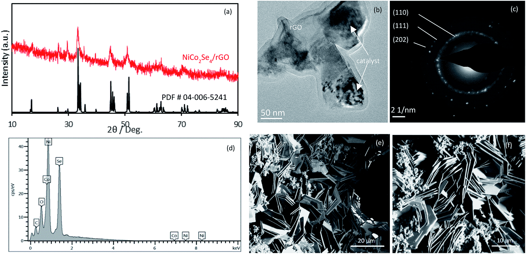 | ||
| Fig. 2 (a) PXRD pattern of as-prepared NiCo2Se4-rGO@NF compared with the standard diffraction pattern. (b) TEM image of NiCo2Se4-rGO@NF. (c) Selected area electron diffraction (SAED) pattern of NiCo2Se4-rGO@NF showing lattice fringes corresponding to NiCo2Se4. (d) EDS microanalysis of the hybrid electrode. (e) Low magnification SEM image of NiCo2Se4-rGO on Ni foam. (f) High magnified SEM image of NiCo2Se4-rGO on Ni foam substrate. | ||
The electrochemical performance of the NiCo2Se4-rGO@NF electrode was examined using cyclic voltammetry (CV) and galvanostatic charge–discharge cycles in a freshly prepared 1 M KOH aqueous solution. In Fig. 3(a) the near rectangular CV curve of rGO on Ni foam in the potential range of 0–0.6 V vs. Ag|AgCl is typical of EDLC charge storage mechanism, as could be expected from porous conducting carbonaceous matrix.15–17 With NiCo2Se4 on the other hand, the distinctive redox peak in the potential range of 0–0.5 V vs. Ag|AgCl verified the electrochemical pseudocapacitor-like behavior of this compound. The CV curve of NiCo2Se4-rGO@NF as shown in Fig. 3(a) clearly shows a pair of oxidation and reduction peaks, illustrating the electrochemical behavior of the electrodes resulting from pseudocapacitive charge storage in conjunction with EDLC behavior which led to a wider potential range of −0.2 to 0.5 V vs. Ag|AgCl for electrochemical activity. The larger integral area of the NiCo2Se4-rGO@NF estimated from the CV plot verified the larger specific capacitance for this compound compared to those of rGO and NiCo2Se4@NF electrodes, respectively. The charge storage of NiCo2Se4-rGO@NF can be attributed to the redox reaction between Ni2+/Ni3+, Co3+/Co4+, and Co2+/Co3+.57,58 NiCo2Se4 crystallizes in a spinel structure type where divalent Ni occupies the tetrahedral sites whereas, trivalent Co occupies the vacancy ordered octahedral layers. However, scrambling of the metal ions between the octahedral and tetrahedral sites has been observed quite frequently in these spinel compounds, leading to presence of mixed oxidation states such as Ni2+/Ni3+ and Co2+/Co3+. Hence, the co-existence of Ni and Co in NiCo2Se4 provides larger density of redox-active reaction sites available on the surface of the electrode composite for electrolyte ions to be adsorbed and desorbed reversibly. Fig. 3(b) shows the CV curves of the NiCo2Se4-rGO@NF within the potential window of −0.2 to 0.5 V at different scan rates ranging from 10–80 mV s−1. With increasing scan rate, position of the oxidation and reduction peaks were slightly changed. The anodic peaks shifted towards more positive potentials while the cathodic peaks moved to negative potentials, confirming the pseudocapacitive behavior of the electrode. It is worth mentioning that, NiCo2Se4-rGO@NF exhibited excellent reversibility and rate performance as there was no noticeable distortion in the shape of the redox peak with increasing scan rates.59 Fig. S5, ESI† shows the relationship between the oxidation and reduction peak currents as a function of scan rate indicating a linear dependence of anodic and cathodic peak currents on the scan rate.
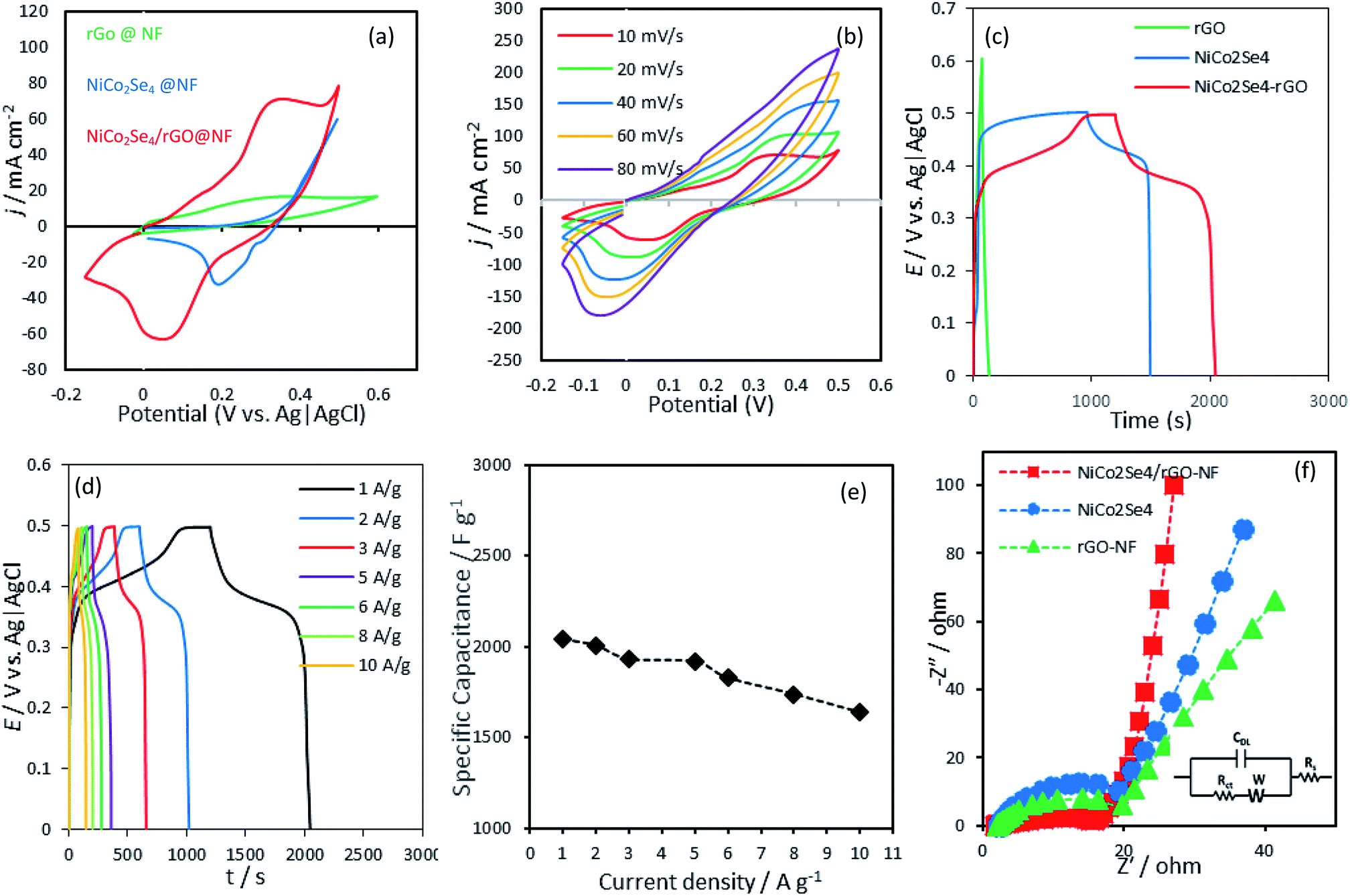 | ||
| Fig. 3 (a) Cyclic voltammograms of rGO@NF, NiCo2Se4@NF and NiCo2Se4-rGO@NF at a scan rate of 10 mV s−1. (b) CV plot of NiCo2Se4-rGO@NF at different scan rates ranging from 10–80 mV s−1. (c) Galvanostatic charge–discharge curves at 1 A g−1. (d) Galvanostatic charge–discharge curve of NiCo2Se4-rGO@NF at different current densities. (e) Specific capacitance measured at different current densities. (f) Nyquist plots of the real and imaginary parts of the impedance spectra for the different catalyst composites. Inset shows the equivalent circuit model. | ||
Fig. 3(c) displays the galvanostatic charge–discharge curve of NiCo2Se4-rGO@NF, NiCo2Se4@NF and rGO@NF electrodes at the current density of 1 A g−1. The triangle shaped charge–discharge curve of rGO@NF is characteristic of a typical EDLC behavior attributable to the small mass transfer resistance and good charge mobility on the rGO@NF electrode composite. The nature of the galvanostatic discharge curve for rGO@NF agrees well with the results obtained from the CV verifying a non-faradaic mechanism of storing charge in the potential range from 0–0.6 V.
The galvanostatic discharge curves corresponding to NiCo2Se4-rGO@NF and NiCo2Se4@NF, on the other hand, demonstrated a normal pseudocapacitive behavior as it showed a sharp decrease in potential until reaching a plateau at 0.4 V and 0.45 V for NiCo2Se4-rGO@NF and NiCo2Se4@NF, respectively. Then, the potential showed a gradual decay until it reached 0.0 V. The galvanostatic discharge curves of NiCo2Se4-rGO@NF and NiCo2Se4@NF were compatible with the result obtained from the CV curves which is based on faradaic redox reaction at the electrode–electrolyte interface within the same potential window. The symmetrical shapes of galvanostatic charge–discharge curves of NiCo2Se4-rGO@NF indicates its superior chemical reversibility of the oxidation–reduction process. In order to evaluate the feasibility of NiCo2Se4-rGO@NF as a hybrid supercapacitor, charge–discharge measurements were performed at different current densities from 1 to 10 A g−1 in the potential range of 0–0.5 V vs. Ag|AgCl (Fig. 3(d)). The specific capacitance (Csp) which indicates the electro-sorption rate and capacity of the NiCo2Se4-rGO@NF composite electrode was calculated from the galvanostatic charge–discharge measurements based on eqn (1). As shown in Fig. 3(e), NiCo2Se4-rGO@NF yields high specific capacitance of 2038.55, 2004.8, 1930.12, 1915.66, 1827.18, 1737.06, and 1636.62 F g−1 at current densities of 1, 2, 3, 5, 6, 8, and 10 A g−1, respectively. The higher specific capacitance at low current densities can be attributed to the complete adsorption and desorption of the hydroxyl groups from the electrolyte to the inner and outer surface of the electrode composite, thereby leading to higher charge transfer. At high current densities, on the other hand, the ions at the outer surface of the electrode are mostly responsible for the charge storage process as the electrolyte has limited access to the inner pores. Accordingly, the specific capacity decreases gradually with increasing the applied current density.60,61
The energy and power density were estimated from the charge–discharge plots by using eqn (2) and (3) as mentioned above. The energy and power density for an asymmetrical cell with NiCo2Se4-rGO@Ni foam as anode and Ni foam as cathode, was estimated to be 67.01 W h kg−1 and 903.61 W kg−1, respectively. To estimate the actual power and energy density from the full device, a symmetrical full cell was also tested by using NiCo2Se4-rGO electrode as both cathode and anode in a 2-electrode setup. The charge–discharge plots at 10, 5, 3, and 2 A g−1 current density has been shown in Fig. S6.†As can be seen from the charge–discharge plots, the active voltage window of the full cell was ∼1.2 V, while the energy density and power density were estimated to be 237 W h kg−1 and 3987 W kg−1−1, respectively at 2 A g−1. Such high energy and power density for the asymmetrical as well as the full cell, confirm efficient supercapacitor behavior of these composite electrodes.
As shown in Table 1, a significantly higher charge storage capacity was achieved for NiCo2Se4-rGO@NF (2038.55 F g−1 at 1.0 A g−1) compared to that of the NiCo2Se4 @NF (1477.6 F g−1) and rGO @NF (238.88 F g−1). The improved performance of this electrode as a supercapacitor can be possibly explained by the larger interlayer separation in lattice structure of the NiCo2Se4 which can facilitate charge transport within the structure as well as the synergistic effect of rGO facilitating charge transfer within the catalyst composite.5,11
| Sample | Potential window (V) | Specific capacitance (F g−1) |
|---|---|---|
| rGO | 0.0–0.6 | 238.8 |
| NiCo2Se4 | 0.0–0.5 | 1477.6 |
| NiCo2Se4/rGO | 0.0–0.5 | 2038.55 |
The electrochemical performance of the active electrode materials comprising NiCo2Se4-rGO@NF, NiCo2Se4@NF and rGO@NF, was evaluated further by EIS measurements performed over the frequency range of 0.1 Hz–100 kHz, in a 1 M KOH electrolyte to provide kinetic and mechanistic information of the charge transfer rate as well as the adsorption/desorption rate of hydroxyl ion on the electrode–electrolyte interface. The charge transfer resistance (Rct) was estimated from EIS plot in the high frequency region as shown in Fig. 3(f). It was observed that the Rct values for NiCo2Se4-rGO@NF was smaller than NiCo2Se4@NF and rGO@NF composite electrodes, indicating faster kinetics for charge transfer at the electrode–electrolyte interface. Such favorable charge transfer results in higher impingement of surface hydroxyl ions leading to higher capacitance. The lower frequency region of the EIS plots illustrates the diffusive resistance of the composite electrodes which influences the mobility of charge carriers within the electrode composite. As can be seen from Fig. 3(f), the Rs value which is an indication of the internal resistance of the electrode composite representing charge transport between the current collector and the electrode shows lower resistance for NiCo2Se4-rGO@NF composite. NiCo2Se4@NF on the other hand, shows higher film resistance highlighting the effect of rGO addition to the composite electrode in enhancing conductivity of the electrode composite.
Stability under several charge–discharge cycles is another key performance metrics for the practical applications of supercapacitors. Fig. 4(a) shows the behavior of NiCo2Se4-rGO@NF composite electrode under several repetitive charge–discharge cycles at 5 A g−1. It was observed that NiCo2Se4-rGO@NF was able to maintain about 90% of its initial specific capacitance after 1000 charge/discharge cycles as shown in Fig. 4(a). The high stability of the NiCo2Se4-rGO@NF can be attributed to the higher active surface area and facile charge transport caused by the intimate interactions between NiCo2Se4 and rGO in this nanocomposite which preserves the capacitance during charge and release of ions. First 100 cycles for the NiCo2Se4-rGO decorated on the Ni foam substrate within the potential range of 0 to 0.5 V at a current density of 5.0 A g−1 exhibited a symmetrical shape with almost similar discharge time without much disparity from the first cycle, which indicates a highly reversible and sustainable charge storage process. Cycle 100 shown in Fig. 4(b) exhibits a specific capacitance of 2032.89 F g−1, while cycle 500 (Fig. 3(c)) shows Csp of 1903.94 F g−1. 1847.88 F g−1 was measured for cycle 700 (Fig. 4(c)), and cycle 1000 shown in Fig. 4(d) gives a specific capacitance of 1814.63 F g−1.
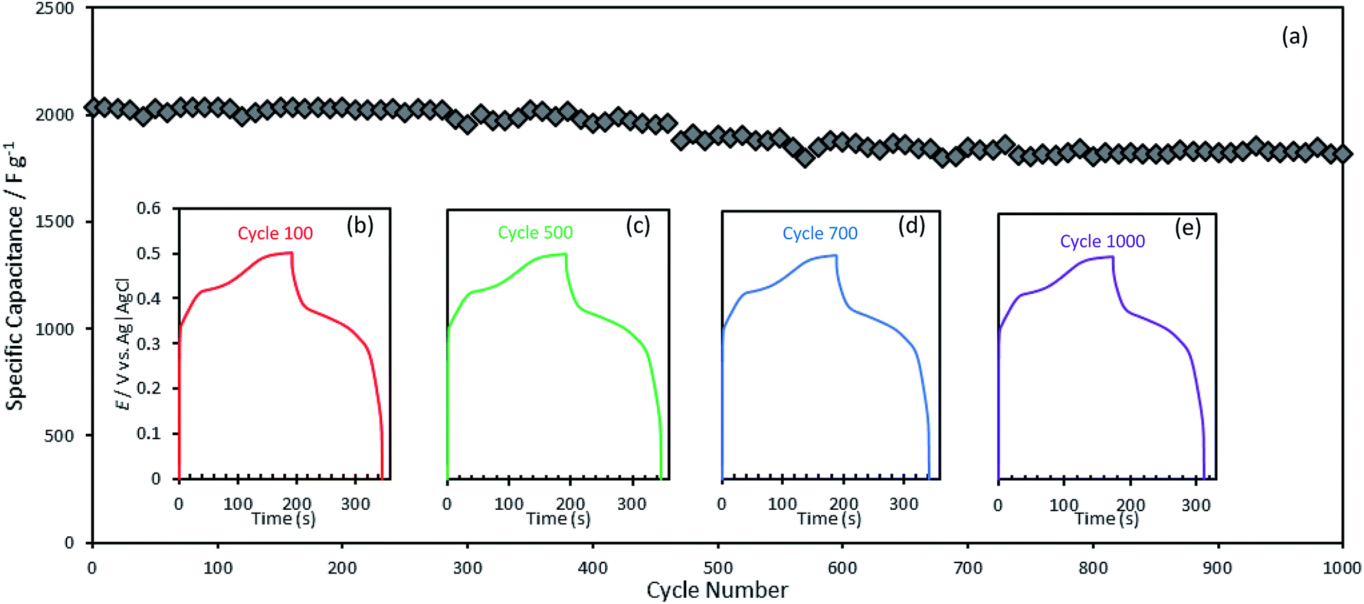 | ||
| Fig. 4 (a) Specific capacitance as a function of number of cycles measured at a current density of 5 A g−1 for stability check. Insets show the galvanostatic charge–discharge plot for the (b) 100th; (c) 500th; (d) 700th; and (e) 1000th cycle. | ||
To examine the possibility of the application of NiCo2Se4-rGO@NF as a flexible electrode for hybrid supercapacitor, electrochemical performance of the as-prepared NiCo2Se4-rGO@NF electrode was measured as a function of electrode film deformation by measuring the galvanostatic charge–discharge curves under three different bending angles of 180°, 90°, 20° shown in Fig. 5(a). Fig. 5(b)–(d) present photographic images of the normal and bent NiCo2Se4-rGO@NF electrode films. As shown in the galvanostatic curves, identical charge–discharge plots were obtained for this hybrid composite electrode under normal and bending conditions, with no change in charge/discharge time. This indicates that contorted NiCo2Se4-rGO@NF electrode retained its mechanical stability as well as capacity retention and full electrochemical performance and is suitable for practical applications in energy storage devices.
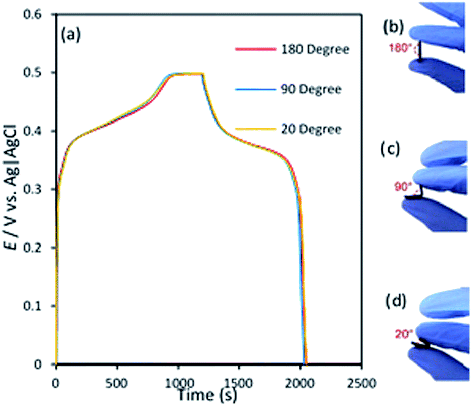 | ||
| Fig. 5 (a) Galvanostatic charge–discharge plot for the NiCo2Se4-rGO@Ni foam electrode at different bend angle of the electrode measured in 1 M KOH. (b)–(d) shows the photographic images of NiCo2Se4-rGO@NF electrode under normal position of 180°, (c) 90°; and (d) 20° bending position. | ||
As described above these transition metal chalcogenide based compositions in conjunction with graphene can show charge storage through both electrochemical redox processes occurring at the transition metal center as well as through double layer capacitance of the high surface area graphene matrix. The electrochemical oxidation-reduction at the transition metal center in alkaline medium is initiated by the adsorption of a hydroxyl anion (OH−) at the transition metal site. Through our previous studies involving DFT calculations it was observed that in Ni- and Co-based selenides, the OH− adsorption energy at both Ni and Co sites are very favorable.63 Such high propensity for OH adsorption leads to these materials having a fast response to charging mechanism resulting in enhanced pseudocapacitive behavior. Having multiple redox-active sites on the surface also increases the specific capacitance and the potential range. The graphene on the other hand, aids in improved charge transport within the catalyst composite leading to increased power density.
Conclusions
NiCo2Se4-rGO@NF was synthesized through a simple one-pot hydrothermal process forming petal-like nanostructures directly grown in Ni foam. Such high density of vertically oriented nanostructures provides large accessible surface area for electrochemical activity and possible charge storage. Such correlation between the morphology of the electrode and the performance of the energy storage system has also been reported in other studies.62 The NiCo2Se4-rGO@NF electroactive material also possesses higher conductivity than NiCo2Se4@NF due to the addition of rGO in the composite which can facilitate charge transport within the catalyst composite. Furthermore, the NiCo2Se4-rGO@NF electrode exhibits a high specific capacitance value of 2038.55 F g−1 at a current density of 1 A g−1 which is stable for over 1000 cycles with minimal capacitance loss. The NiCo2Se4-rGO composite electrode also shows retention of full electrochemical performance independent of bending deformation of the electrode film. Superior energy density of 67.01 W h kg−1, high power density of 903.61 W kg−1 for the asymmetrical cell along with an excellent mechanical stability at different bending conditions, and functional stability for over 1000 cycles makes NiCo2Se4-rGO@NF a promising candidate for the future energy storage technology.Conflicts of interest
There are no conflicts to declare.Acknowledgements
This work was partially supported through NSF funds (DMR 1710313).Notes and references
- Y. Tang, S. Chen, S. Mu, T. Chen, Y. Qiao, S. Yu and F. Gao, ACS Appl. Mater. Interfaces, 2016, 8, 9721–9732 CrossRef CAS PubMed.
- J. Chang, Z. Gao, X. Wang, D. Wu, F. Xu, X. Wang, Y. Guo and K. Jiang, Electrochim. Acta, 2015, 157, 290–298 CrossRef CAS.
- Y. Wen, S. Peng, Z. Wang, J. Hao, T. Qin, S. Lu, J. Zhang, D. He, X. Fan and G. Cao, J. Mater. Chem. A, 2017, 5, 7144–7152 RSC.
- S. Zheng, X. Li, B. Yan, Q. Hu, Y. Xu, X. Xiao, H. Xue and H. Pang, Adv. Energy Mater., 2017, 7, 1602733 CrossRef.
- S. Srinivasa Rao, I. K. Durga, N. Kundakarla, D. Punnoose, C. V. V. M. Gopi, A. E. Reddy, M. Jagadeesh and H.-J. Kim, New J. Chem., 2017, 41, 10037–10047 RSC.
- Z.-S. Wu, Y.-Z. Tan, S. Zheng, S. Wang, K. Parvez, J. Qin, X. Shi, C. Sun, X. Bao, X. Feng and K. Müllen, J. Am. Chem. Soc., 2017, 139, 4506–4512 CrossRef CAS PubMed.
- H. Chen, S. Chen, M. Fan, C. Li, D. Chen, G. Tian and K. Shu, J. Mater. Chem. A, 2015, 3, 23653–23659 RSC.
- P. Simon and Y. Gogotsi, Nat. Mater., 2008, 7, 845 CrossRef CAS PubMed.
- Q. Q. Xiong, J. P. Tu, X. H. Xia, X. Y. Zhao, C. D. Gu and X. L. Wang, Nanoscale, 2013, 5, 7906–7912 RSC.
- M. Zhi, C. Xiang, J. Li, M. Li and N. Wu, Nanoscale, 2013, 5, 72 RSC.
- Y. Li, L. Xu, M. Jia, L. L. Cui, J. Gao and X.-J. Jin, J. Electrochem. Soc., 2018, 165, 303–310 CrossRef.
- H. Yan, T. Li, K. Qiu, Y. Lu, J. Cheng, Y. Liu, J. Xu and Y. Luo, J. Solid State Electrochem., 2015, 19, 3169–3175 CrossRef CAS.
- Y. Tian, Y. Ruan, J. Zhang, Z. Yang, J. Jiang and C. Wang, Electrochim. Acta, 2017, 250, 327–334 CrossRef CAS.
- A. Pendashteh, S. E. Moosavifard, M. S. Rahmanifar, Y. Wang, M. F. El-Kady, R. B. Kaner and M. F. Mousavi, Chem. Mater., 2015, 27, 3919–3926 CrossRef CAS.
- S. K. Kim, T. Ha, C. Lee, H. Chang and H. D. Jang, Macromol. Rapid Commun., 2019, 1800832 CrossRef PubMed.
- M. Chen, D. Yu, X. Zheng and X. Dong, J. Energy Storage, 2019, 21, 105–112 CrossRef.
- J. Huang, B. G. Sumpter and V. Meunier, Angew. Chem., Int. Ed., 2008, 47, 520–524 CrossRef CAS PubMed.
- S. Sahoo, S. Zhang and J.-J. Shim, Electrochim. Acta, 2016, 216, 386–396 CrossRef CAS.
- Y. Zhang, M. Park, H. Y. Kim and S.-J. Park, J. Colloid Interface Sci., 2017, 500, 155–163 CrossRef CAS PubMed.
- M. Sethi and D. K. Bhat, J. Alloys Compd., 2019, 781, 1013–1020 CrossRef CAS.
- Y.-R. Zhu, P.-P. Peng, J.-Z. Wu, T.-F. Yi, Y. Xie and S. Luo, Solid State Ionics, 2019, 336, 110–119 CrossRef CAS.
- S. Wen, K. Qin, P. Liu, N. Zhaoa, C. Shi, L. Ma and E. Liu, J. Alloys Compd., 2019, 783, 625–632 CrossRef CAS.
- W. Ge, W. Peng, A. Encinas, M. F. Ruiz and S. Song, Chem. Phys., 2019, 521, 55–60 CrossRef CAS.
- M. Xie, Z. Xu, S. Duan, Z. Tian, Y. Zhang, K. Xiang, M. Lin, X. Guo and W. Ding, Nano Res., 2018, 11, 216–224 CrossRef CAS.
- N. S. Arul and J. I. Han, Mater. Lett., 2016, 181, 345–349 CrossRef CAS.
- Q. Bao, J. Wu, L. Fan, J. Ge, J. Dong, J. Jia, J. Zeng and J. Lin, J. Energy Chem., 2017, 26, 1252–1259 CrossRef.
- Y. Zhang, A. Pan, Y. Wang, X. Cao, Z. Zhou, T. Zhu, S. Liang and G. Cao, Energy Storage Materials, 2017, 8, 28–34 CrossRef.
- X. Wang, B. Liu, Q. Wang, W. Song, X. Hou, D. Chen, Y. -b. Cheng and G. Shen, Adv. Mater., 2013, 25, 1479–1486 CrossRef CAS PubMed.
- D. Jiang, H. Liang, W. Yang, Y. Liu, X. Cao, J. Zhang, C. Li, J. Liu and J. J. Gooding, Carbon, 2019, 146, 557–567 CrossRef CAS.
- V. Ojha, K. Kato, M. A. Kabbani, G. Babu and P. M. Ajayan, ChemistrySelect, 2019, 4, 1098–1102 CrossRef CAS.
- R. Wang, X. Yan, J. Lang, Z. Zheng and P. Zhang, J. Mater. Chem. A, 2014, 2, 12724–12732 RSC.
- X. Zhao, C. Johnston and P. S. Grant, J. Mater. Chem., 2009, 19, 8755–8760 RSC.
- V. H. R. Souza, M. M. Oliveira and A. J. G. Zarbin, J. Power Sources, 2017, 348, 87–93 CrossRef CAS.
- Y. Zhu, S. Murali, W. Cai, X. Li, J. W. Suk, J. R. Potts and R. S. Ruoff, Adv. Mater., 2010, 22, 3906–3924 CrossRef CAS PubMed.
- R. Chen, L. Liu, L. Hou, J. Zhou and F. Gao, ChemElectroChem, 2017, 4, 2250–2259 CrossRef CAS.
- N.-L. Wu, Mater. Chem. Phys., 2002, 75, 6–11 CrossRef CAS.
- V. H. Nguyen and J.-J. Shim, Electrochim. Acta, 2015, 166, 302–309 CrossRef CAS.
- M. A. Garakani, S. Abouali, Z.-L. Xu, J. Huang, J.-Q. Huanga and J.-K. Kim, J. Mater. Chem. A, 2017, 5, 3547–3557 RSC.
- V. H. Nguyen and J.-J. Shim, Synth. Met., 2015, 207, 110–115 CrossRef CAS.
- H.-W. Wang, Z. Ai Hu, Y.-Q. Chang, Y.-L. Chen, H.-Y. Wu, Z.-Y. Zhang and Y.-Y. Yang, J. Mater. Chem., 2011, 21, 10504–10511 RSC.
- Q. Li, C. Lu, C. Chen, L. Xie, Y. Liu, Y. Li, Q. Kong and H. Wang, Energy Storage Materials, 2017, 8, 59–67 CrossRef.
- B. G. Amin, A. T. Swesi, J. Masud and M. Nath, Chem. Commun., 2017, 53, 5412–5415 RSC.
- J. Masud and M. Nath, ACS Energy Lett., 2016, 1, 27–31 CrossRef CAS.
- U. D. Silva, J. Masud, N. Zhang, Y. Hong, W. P. R. Liyanage, M. A. Zaeem and M. Nath, J. Mater. Chem. A, 2018, 6, 7608–7622 RSC.
- J. Masud, A. T. Swesi, W. P. R. Liyanage and M. Nath, ACS Appl. Mater. Interfaces, 2016, 8, 17292–17302 CrossRef CAS PubMed.
- B. G. Amin, J. Masud and M. Nath, J. Mater. Chem. B, 2019, 7, 2338–2348 RSC.
- B. G. Amin, U. D. Silva, J. Masud and M. Nath, ACS Omega, 2019, 4(6), 11152–11162 CrossRef PubMed.
- Y. Gu, L.-Q. Fan, J.-L. Huang, C.-L. Geng, J.-M. Lin, M.-L. Huang, Y.-F. Huang and J.-H. Wu, J. Power Sources, 2019, 425, 60–68 CrossRef CAS.
- J. Yang, Z. Sun, J. Wang, J. Zhang, Y. Qin, J. You and L. Xu, CrystEngComm, 2019, 21, 994–1000 RSC.
- A. M. Zardkhoshoui, S. S. H. Davarani and A. A. Asgharinezhad, Dalton Trans., 2019, 48, 4274–4282 RSC.
- A. T. Swesi, J. Masud, W. P. R. Liyanage, S. Umapathi, E. Bohannan, J. Medvedeva and M. Nath, Sci. Rep., 2017, 7, 2401 CrossRef PubMed.
- P. K. Kannan, B. Dinesh, C. Y. An and C.-H. Chung, ChemistrySelect, 2017, 2, 1967–1973 CrossRef.
- X. Chen, D. Chen, X. Guo, R. Wang and H. Zhang, ACS Appl. Mater. Interfaces, 2017, 9, 18774–18781 CrossRef CAS PubMed.
- L. Ma, Y. Hu, R. Chen, G. Zhu, T. Chen, H. Lv, Y. Wang, J. Liang, H. Liu, C. Yan, H. Zhu, Z. Tie, Z. Jin and J. Liu, Nano Energy, 2016, 24, 139–147 CrossRef CAS.
- T. Zhu, G. Zhang, T. Hu, Z. He, Y. Lu, G. Wang, H. Guo, J. Luo, C. Lin and Y. Chen, J. Mater. Sci., 2016, 51, 1903–1913 CrossRef CAS.
- Y.-Z. Su, K. Xiao, N. Li, Z.-Q. Liu and S.-Z. Qiao, J. Mater. Chem. A, 2014, 2, 13845–13853 RSC.
- L. Mei, T. Yang, C. Xu, M. Zhang, L. Chen, Q. Li and T. Wang, Nano Energy, 2014, 3, 36–45 CrossRef CAS.
- Q. Wang, Y. Ma, Y. Wu, D. Zhang and M. Miao, ChemSusChem, 2017, 10, 1–10 CrossRef.
- Z. Chen, D.-B. Xiong, X. Zhang, H. Ma, M. Xia and Y. Zhao, Nanoscale, 2016, 8, 6636–6645 RSC.
- M. H. Naveen, K. Shim, Md. S. A. Hossain, J. H. Kim and Y. B. Shim, Adv. Energy Mater., 2016, 1602002, 1–9 Search PubMed.
- M. D. Stoller and R. S. Ruoff, Energy Environ. Sci., 2010, 3, 1294–1301 RSC.
- A. M. Zardkhoshoui, S. S. H. Davarani and A. A. Asgharinezhad, Dalton Trans., 2019, 48, 4274 RSC.
- X. Cao, Y. Hong, N. Zhang, Q. Chen, J. Masud, M. A. Zaeem and M. Nath, ACS Catal., 2018, 8, 8273–8289 CrossRef CAS.
Footnote |
| † Electronic supplementary information (ESI) available: XRD, TEM, SAED, EDS and SEM image of NiCo2Se4, current as the function of scan rate plot, comparison table. See DOI: 10.1039/c9ra06439g |
| This journal is © The Royal Society of Chemistry 2019 |