
 Open Access Article
 This Open Access Article is licensed under a Creative Commons Attribution-Non Commercial 3.0 Unported Licence
Light-controlled two-dimensional TiO2 plate micromotors†
Ying Wangab,
Zhen Lib,
Alexander A. Solovev a,
Gaoshan Huang*a and
Yongfeng Meia
a,
Gaoshan Huang*a and
Yongfeng Meia
aDepartment of Materials Science, Fudan University, Shanghai 200433, People's Republic of China. E-mail: gshuang@fudan.edu.cn
bDepartment of Physics and Mathematics, Shanghai University of Electric Power, Shanghai 201300, People's Republic of China
First published on 17th September 2019
Abstract
In this work, UV light-controlled two-dimensional (2D) TiO2 plate micromotors are demonstrated for the first time. The 2D TiO2 micromotors are produced by the well-known anodic oxidation method in combination with a cracking and separation process. When the motor is placed in H2O2 aqueous solution under UV irradiation, oxygen bubbles are generated in the holes of the TiO2 membrane. The 2D micromotor thus moves upon O2 bubbles under its own weight. In contrast to bubble-propelled micromotors, which require an addition of surfactants to chemical fuels, the 2D micromotor is capable of moving in aqueous H2O2 solution without surfactants. Moreover, speed of the 2D TiO2 micromotor can be controlled by the intensity of the UV light. Such surfactant-free micromotors and their facile fabrication hold considerable promise for diverse practical applications in the biomedical and energy fields, for example, and in new materials.
1. Introduction
Autonomous locomotion of micro-/nano-objects in fluids has attracted a lot of attention for its potential applications such as in cargo delivery, protein and cell separation, microsurgery, and water remediation.1–10 In such cases, micro-/nano-motor-based catalytic micro-/nano-machines can efficiently convert chemical energy into kinetic energy of motion. Usually, in order to power the micro-/nano-motors, extra fuels are required, including well studied H2O2,11–13 hydrazine,14 acidic,15 and alkaline-based fuels.15 From the viewpoint of practical applications of micromotors, steering them in a precise and controllable way, e.g., controllable activation, directionality and speed, is of great advantage. So far, multiple external fields (e.g. light, magnetic fields, electric fields, and ultrasound waves) have been adopted to drive the motors.16–21 In particular, light irradiation is one of the most interesting energy sources and has important prospects for applications in photo-activated and controlled micro-/nano-motors.Many different kinds of photo-activated micro-/nano-motors have been developed so far. The geometries of the motors include small particles (i.e., 0D structures),22 rods (i.e., 1D structures),23 tubes,9,11,24 and capsules (i.e., 3D structures).25,26 For example, Dong and coworkers demonstrated the efficient propulsion of UV light-driven TiO2–Au Janus micromotors in water.27 Zhou et al.28 described a visible light-driven microparticle structured Cu2O–Au micromotor that displayed autonomous motion in low concentration H2O2 solution. Mou and co-workers demonstrated tube-structured light-controlled micromotors.29 Wong et al.30 have developed light-activated AgI–Pt nanorod micromotors and Ag–Pt micropump systems. Wu and coworkers described polymer-based microtubular engines activated by near-infrared laser.19 Most of the light-driven micro-/nano-motors reported to date are of 0D, 1D, and 3D micro-/nano-structures, and compared with these structures, the plate-like porous 2D micromotors have high loading capacity.31 Recently, crystalized porous TiO2 membrane-based motor was introduced as the first demonstration of 2D porous nanomotor, where ∼30 particles were loaded.31 In general, amorphous TiO2 is inactive under UV irradiation, because the photo-generated electrons and holes recombine with each other efficiently.32 However, when Am-TiO2 was sensitized by H2O2, it possess a superior photocatalytic activity compared with the crystalline TiO2, and the surface peroxide complexes can effectively enhance separation ability for the photo-generated charge pair.32 Thus, light-driven micromotor fabricated from amorphous TiO2 may possess enhanced performance while the related research is still scarce.
In addition, the presence of surfactant in the environment is generally necessary for the movement of most bubble-propelled micro-/nano-motors, as it lowers interfacial tension required for detachment of the bubble from the micro-/nano-motors.33 However, it is considered that an addition of surfactant is not biocompatible and can be harmful for environment.4 Therefore, micro-/nano-motors that can efficiently move in fluids without surfactant are highly desired.
In this work, we design amorphous TiO2 2D micromotors (Am-TiO2 2D micromotors) by separating anodic TiO2 membranes into bunches of TiO2 nanotubes. We demonstrate that these Am-2D-TiO2 micromotors can be driven by UV light via a so-called bubble-supported gravitational propelling. We notice that the motion mode of Am-TiO2 2D micromotor is entirely different in comparison to previously observed bubble-propelled mechanism. For the bubble-propelled motors, the moving directions of the motor and the bubble are opposite.8,9,34,35 However, the Am-2D-TiO2 micromotors moved upon the generated bubbles. During the movement, the photo-generated O2 molecules firstly accumulate in the holes at the bottom of the motor and grow into bubbles with different radii. The pushing force from the bubbles makes the 2D micromotor float on the bubbles with an angle between the 2D micromotor and horizontal plane, due to different radii of the bubbles. Then, the gravity of the 2D micromotor causes the motor move along the direction from larger bubble to small bubble. Our work demonstrates that when the motor is exposed to UV light, the bubble-supported gravitational propulsion is immediately triggered which efficiently drives the micromotors in H2O2 solution without any surfactants. Moreover, the motor can be intentionally switched on or off by the light source, and the velocity of Am-TiO2 2D micromotor can be adjusted on demand by altering the light intensity.
2. Experimental
2.1 Preparation of Am-TiO2 2D micromotors
A Ti foil was used to fabricate TiO2 porous membrane by an electrochemical anodization process. Before anodizing, the Ti foil was sonicated in acetone, isopropyl alcohol, and deionized water, and then dried on a hotplate at 120 °C. The solution used in anodizing process was a mixture of 100 mL ethylene glycol (99.8%), 10 mL H3PO4 (85%), and 1 mL hydrogen fluoride (HF) (48%). Anodizing process was performed at room temperature for 1 h under a DC voltage of 90 V. The obtained anodic TiO2 porous membrane was then placed in ethanol. After an ultrasonication procedure for 1 min at a frequency of 40 kHz, TiO2 porous membrane was divided into small pieces containing nanotubes (i.e., 2D micromotors), and the average size of the pieces was ∼2500 μm2. Ultrasonication treatment with shorter time resulted in non-uniform size distribution of the pieces while longer ultrasonication treatment led to small pieces, which could not move efficiently.2.2 Microstructural characterizations
Scanning electron microscopy (SEM) and energy-dispersive X-ray (EDX) analysis were obtained by using a Hitachi S-4800 field-emission SEM. X-ray diffraction pattern (XRD) was obtained by using a Rigaku D/Max-RB diffractometer at a voltage of 40 kV and a current of 20 mA with Cu-Kα radiation.2.3 Motion investigations
An optical microscope (Olympus BX51) with an integrated high-speed camera was adopted to capture the locomotion of Am-TiO2 2D micromotors. In order to trigger the micromotors, a UV light-emitting diode was placed above the solution containing micromotors. The power density was experimentally tuned by varying the distance between light source and the solution, and measured by using an optical power meter.3. Results and discussion
The Am-TiO2 2D micromotors are fabricated by a facile anodic oxidation method followed by a ultra-sound induced cracking process. Fig. 1a shows that the Am-TiO2 2D micromotor consists of an array of TiO2 nanotubes. The TiO2 nanotubes have a constant outer diameter of ∼150 nm (see the enlarged image in the white rectangle). The inner diameter gradually decreases from 100 nm at the wide end to 30 nm at the narrow end (Fig. S1†). In addition, one can see several holes on the surface of TiO2 membrane (white circles in Fig. 1a). These holes can store gas bubbles, as we will discuss in detail later. Fig. 1b shows EDX analysis of the elemental composition of the Am-TiO2 2D micromotor, indicating the sample containing only titanium and oxygen. The atomic proportion of titanium to oxygen is 1/2, as expected from the anodic oxidation process of Ti sheet. The broad and weak XRD peak in the inset of Fig. 1b confirms that TiO2 in the micromotor is amorphous. In the present work, an array of TiO2 nanotubes with a height/thickness around ∼5 μm is explored for light-controlled micromotor application.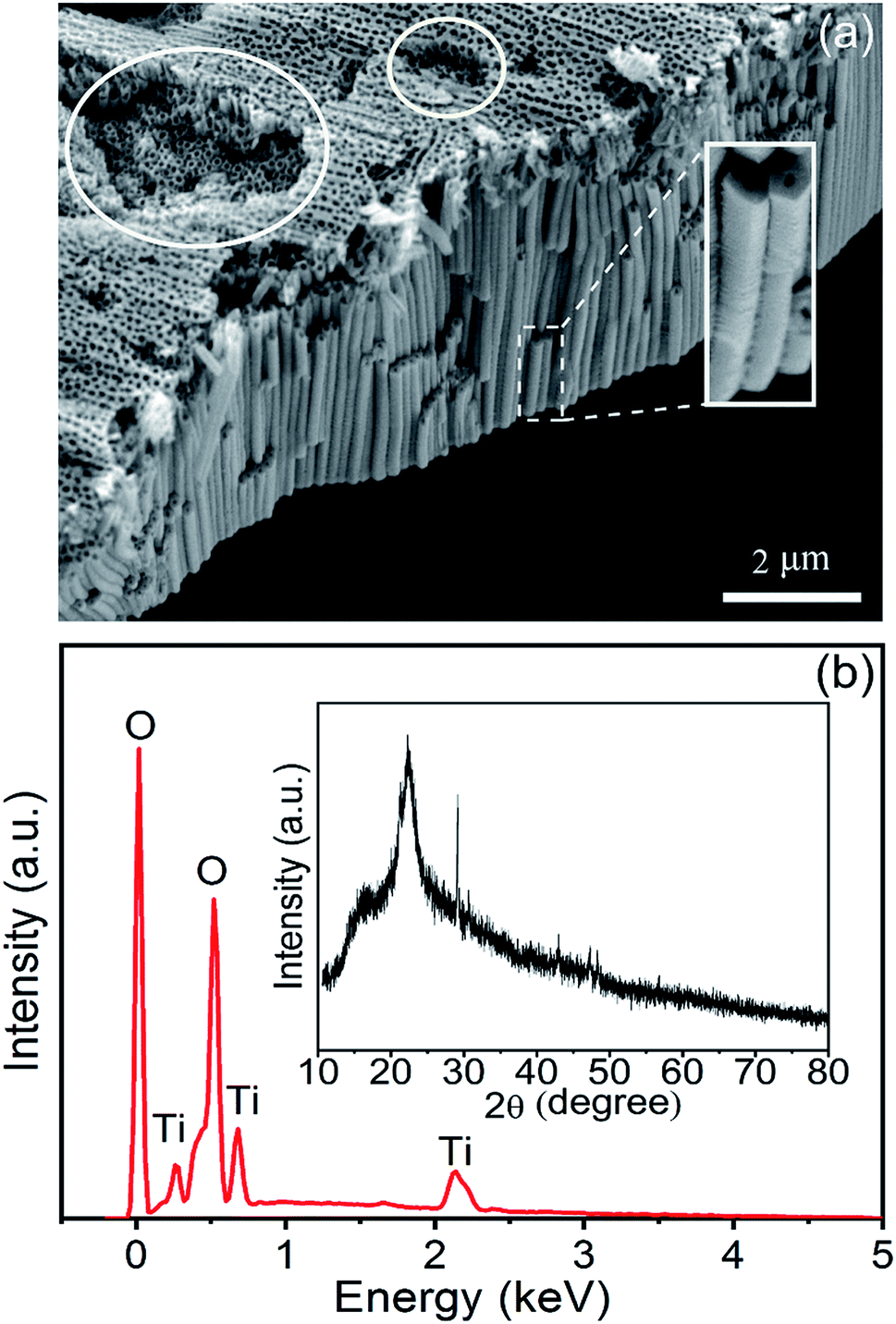 | ||
| Fig. 1 (a) SEM image of the sample. (b) EDX spectrum and XRD pattern (inset) of the as-prepared sample. | ||
The efficient photocatalytic H2O2 decomposition over the amorphous TiO2 under UV irradiation plays a crucial role in the light-controlled propulsion of the Am-TiO2 2D micromotors. Usually, for TiO2, only crystalline phases such as anatase, rutile, and anatase/rutile mixed phases are photocatalytically active under UV irradiation.29,36 Amorphous TiO2 has high density of defects,32 and the facilitated recombination of photogenerated electrons and holes makes amorphous TiO2 nearly inactive under UV irradiation.32 However, when amorphous TiO2 is sensitized by H2O2, the amorphous TiO2 exhibits an efficient photocatalytic activity even higher than that of crystalline TiO2.37–39 Amorphous TiO2 decomposes the H2O2 fuel in the presence of UV light according to equations:29,40
| TiO2 + hν → h+ + e− | (1) |
| H2O2 + 2h+ → O2 + 2H+ | (2) |
| H2O2 + 2e− + 2H+ → O2 + 2H2O | (3) |
Video 1, ESI† and Fig. 2 show the photoactive motion of the Am-TiO2 2D micromotor in 10 wt% H2O2 without any surfactant, and the power density of UV light is 0.5 W cm−2. Once the UV light is on, the Am-TiO2 2D micromotor moves upon O2 bubbles with diameter of ∼50 μm (Fig. 2b–d), which comes out from the bottom side of the 2D micromotor. Although the bubble generation rate is 2 s−1, a remarkable motion speed of 53 μm s−1 is observed for the 2D micromotor. When the UV light is off, the 2D micromotor stops immediately (Video 1, ESI† and Fig. 2c). When the UV light is turned on again (Fig. 2d), the 2D micromotor can be reactivated within 0.5 s, indicating the fast response ability of the 2D micromotor upon the UV irradiation. Compared with bubble-propelled catalytic micromotors, the present 2D micromotor demonstrates a different moving mode. From Video 1, ESI,† one can see that the bubbles come out from the bottom, while the Am-TiO2 2D micromotor moved laterally. The observed phenomenon implies a new moving mechanism for the 2D micromotors, which will be discussed in detail later.
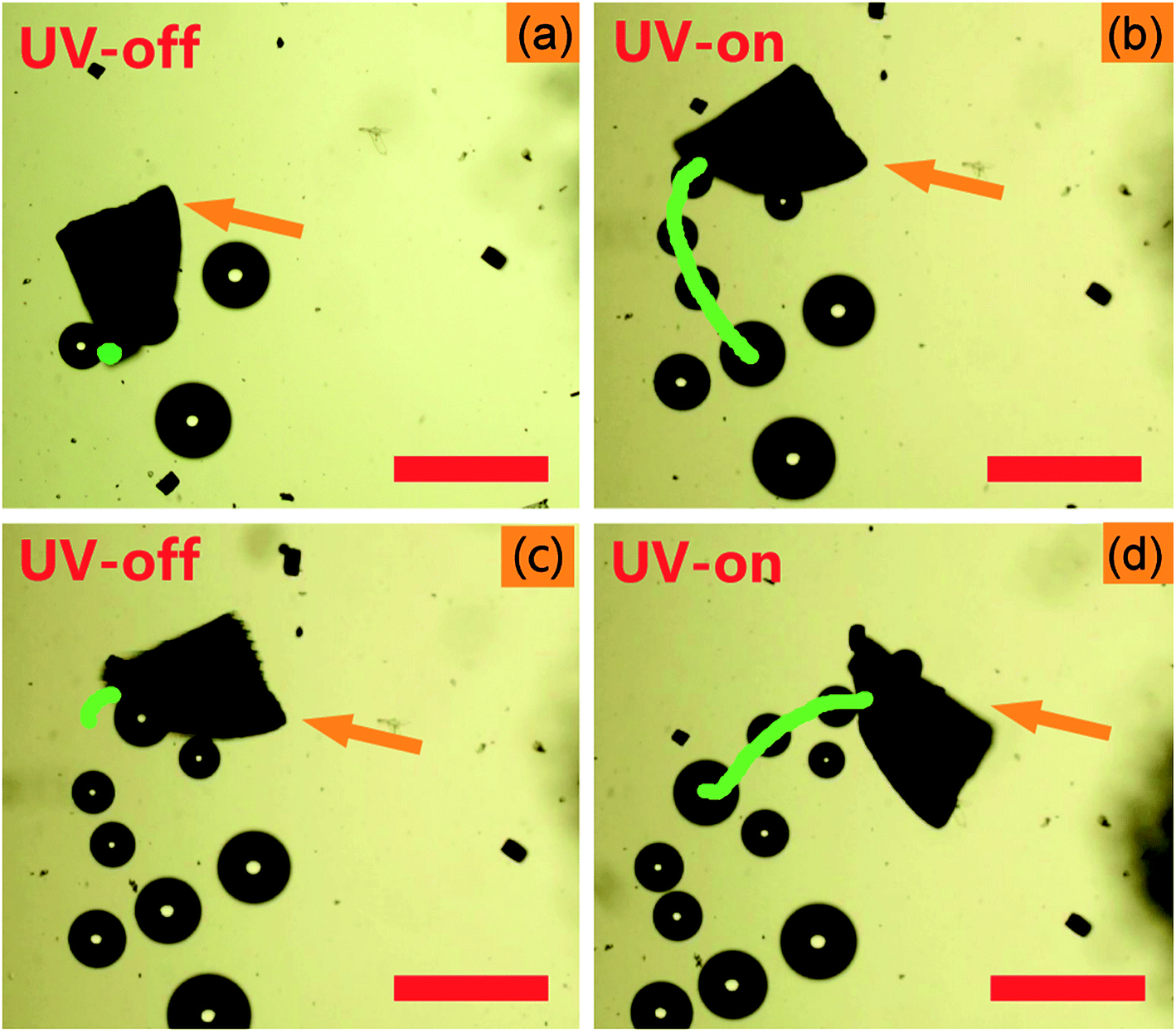 | ||
| Fig. 2 Time-lapse images of the light-controlled motion of the Am-TiO2 2D micromotor in 10 wt% H2O2 at: (a) 3 s, (b) 6 s, (c) 9 s, and (d) 12 s. The orange arrows indicate the Am-TiO2 2D micromotor. The green lines in (a), (b), (c), and (d) correspond to motion trajectories at time slots of 0–3, 3–6, 6–9, and 9–12 s, respectively. The micromotors are irradiated by the UV light with a power density of 0.5 W cm−2, and the UV light is on during 3–6 s and 9–12 s (Video 1, ESI†). Scale bars: 200 μm. | ||
To explore the factors which can influence the motion of Am-TiO2 2D micromotor, we studied the motion speed of the micromotor under different light intensities and H2O2 concentrations. Video 2, ESI† and Fig. 3a reveal that when power density of the UV light increases from 0.2 to 0.5 W cm−2, the speed of the 2D micromotors increases from 23 to 52 μm s−1. A linear relationship between the motor speed and the light power density is observed (Fig. 3a). However, there is no motion observed for the 2D micromotors, when UV light power density is less than 0.1 W cm−2, and bubbles ejection is sparsely observed. This indicates that a lower limit of the UV light power density should exist, and the motor begins to move when the light power density is larger than this value. Video 3, ESI† and Fig. 3b show the moving velocities of Am-TiO2 2D micromotor in H2O2 solutions with different concentrations. The speed of the micromotors is ∼24 μm s−1 in 1 wt% H2O2 and it increases to 49 μm s−1 in 8 wt% H2O2. However, as the concentration increased from 8 wt% to 10 wt%, the speed increase slowly. One can see that the velocity is not linearly proportional to the H2O2 concentration in the range of 1–10 wt%, suggesting that the energy conversion efficiency of the catalytic motion is rate-limiting.28
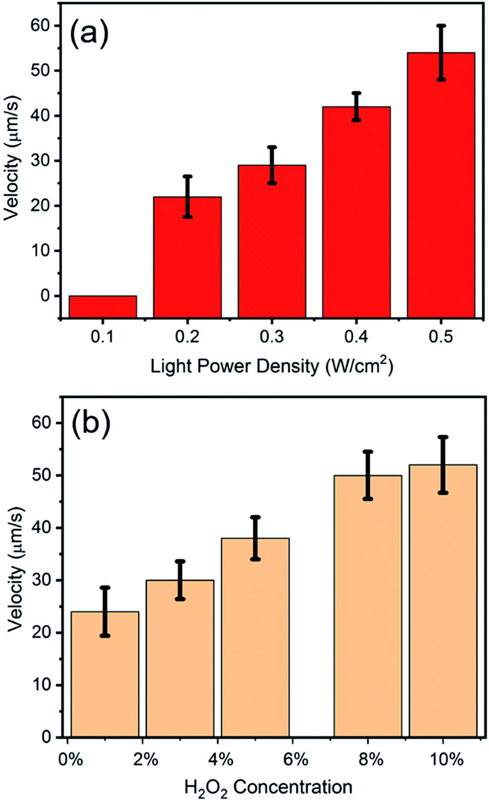 | ||
| Fig. 3 (a) Velocity of the Am-TiO2 2D micromotors under different UV light power densities, tested in 10 wt% H2O2. (b) Velocity of the Am-TiO2 2D micromotors in H2O2 with different concentrations, irradiated by the UV light with a power density of 0.5 W cm−2. | ||
In order to better understand the motion mechanism of the Am-TiO2 2D micromotor under UV illumination, we analyzed the motion in details and six bubbles are specifically tracked (see Video 4, ESI†). Fig. 4a–f show the release of six O2 bubbles produced by the micromotor. Fig. 4a shows three bubbles with different sizes, which are indicated as 1, 2, and 3 respectively, and the radii of the bubbles are R1 > R2 > R3. In the present case, the different bubble size is considered to be due to the growth of bubble in the holes with different sizes (Fig. 1a), which can be used to store gas and produce bubbles. Firstly, the 2D micromotor moves upon the bubbles, along the direction from bubble 1 to bubble 2 (Fig. 4b–c). Then, the 2D micromotor moves from bubble 2 to bubble 3, leaving bubbles 1 and 2 behind (Fig. 4d). Here, bubble 1 merges into another bubble, and its initial position is marked with a dashed circle. At the same time, bubble 4 (R4 < R3) forms at the bottom of the 2D micromotor (Fig. 4d). When the 2D micromotor moved from bubble 3 to bubble 4, bubble 5 and bubble 6 appear (Fig. 4e and f). The formation of the three bubbles (bubbles 4–6) with different sizes (R4 > R5 > R6) at the same positions as those of bubbles 1–3, suggesting another moving cycle, and therefore the motion continues.
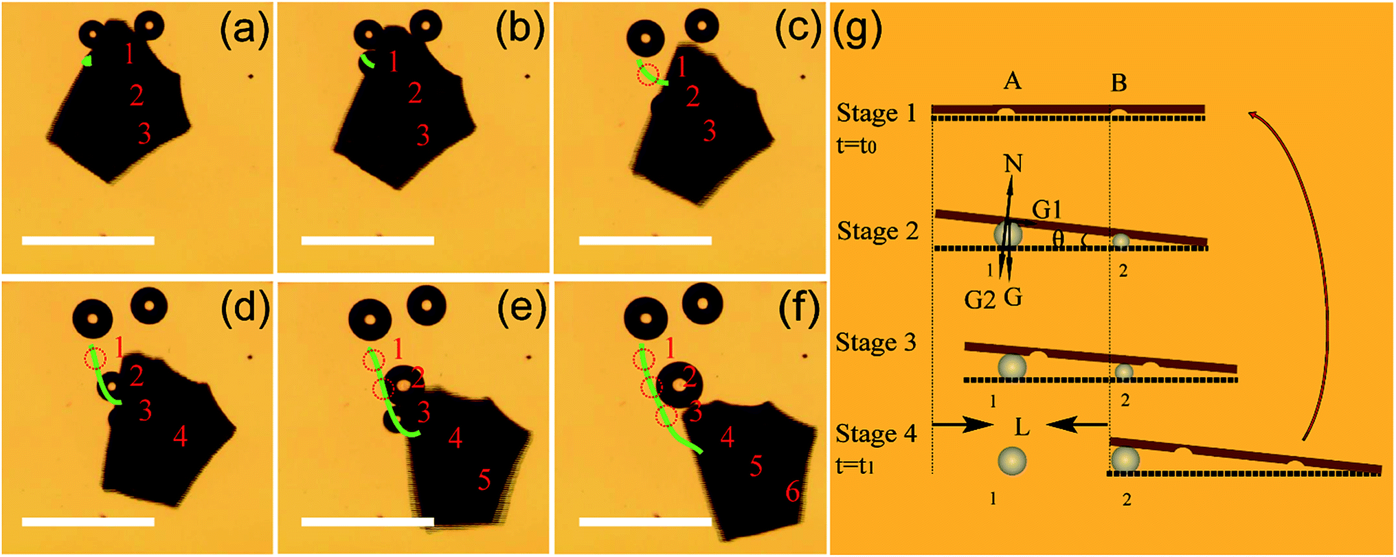 | ||
| Fig. 4 Time-lapse images of the Am-TiO2 2D micromotor in the fuel containing 10 wt% H2O2 with UV light power density of 0.5 W cm−2 at (a) 0, (b) 0.5, (c) 1, (d) 1.5, (e) 2, and (f) 5 s. The green lines in (a)–(f) are motion trajectories and bubbles are marked. Scale bar: 200 μm. (g) The diagram of the motion mechanism of the Am-TiO2 2D micromotor in H2O2 fuel. | ||
The UV-induced motion of the Am-TiO2 2D micromotor in H2O2 fuel is schematically illustrated in Fig. 4g and it can be divided into four stages. Firstly, without UV irradiation, no bubble or movement is generated for the 2D micromotor (Stage 1, t = t0). For the sake of simplicity, we assume that there are two holes with different sizes at the bottom side of the 2D micromotor, which are signed as A and B in Fig. 4g. When a UV light is on, the photogenerated O2 molecules can accumulated in these holes. When the holes are full of O2 molecules, two bubbles with different radii (R1 > R2) are formed, as shown in Stage 2 of Fig. 4g. In Stage 3, the pushing force N from the bubbles make the 2D micromotor float on them. Because of different radii of the bubbles, a tilt angle θ between the surface of 2D micromotor and horizontal plane appears, and gravity G can be divided into two components G1 and G2. As illustrated in Fig. 4g, the G1 and G2 can be expressed as:
G1 = G![[thin space (1/6-em)]](https://www.rsc.org/images/entities/char_2009.gif) sin(θ) = Mgsin(θ), sin(θ) = Mgsin(θ),
| (4) |
|
G2 = Gcos(θ) = Mgcos(θ) = N,
| (5) |
In Stage 3, the gravity component G1 makes the 2D micromotor moving along the G1 direction. Then, the system evolves to Stage 4, and the movement in one step with a distance of L is accomplished. One can see that for movement in one step, the micromotor moves from big bubbles to small bubbles (Fig. 4g), and the process cycles to achieve continuous movement. Based on above eqn (4) and (5), we conclude that the average velocity ![[V with combining macron]](https://www.rsc.org/images/entities/i_char_0056_0304.gif) for 2D micromotor can be written as
for 2D micromotor can be written as
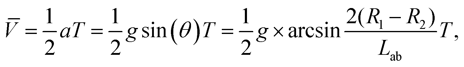 | (6) |
The surfactant plays a major role in reducing the surface tension of the fuel and generating bubbles at high rate.41,42 Therefore, the velocity of bubble-propelled micro-/nano-motors in previous studies is remarkably higher if surfactants are added.33 However, the present Am-TiO2 2D micromotor demonstrated different motion behaviors, and the surfactant could not promote the locomotion of such micromotors. On the contrary, we found that the surfactant could hinder the movement of the Am-TiO2 2D micromotor. In our experiment, we studied the influence of surfactant on the motion behavior by observing the locomotions of Am-TiO2 2D micromotors in solutions containing sodium dodecyl sulfate (SDS) with different concentrations (0, 0.3, 1, 2, and 5 wt%). Video 5, ESI† and Fig. 5a show that without surfactant, the bubbles with different sizes start to grow at the bottom side of the 2D micromotor once the UV irradiation is on. The 2D micromotor then effectively moves upon the generated bubbles. On the contrary, low SDS concentration (i.e., 0.3 and 1 wt%) led to slightly decreased motion speed. After 2 wt% or more SDS being added, both the number of the bubbles and the bubble production rate are increased. However, the 2D micromotor can hardly move, as shown in Fig. 5b. With further increase of the SDS concentration to 5 wt%, the 2D micromotor cannot move, although more bubbles come out from the bottom (Fig. 5c). It is therefore concluded that for the 2D micromotor the surfactant cannot promote, but make against the efficiency of locomotion. This phenomenon is further discussed below.
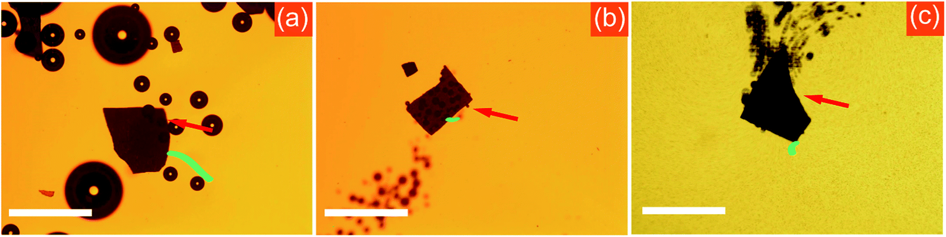 | ||
| Fig. 5 Motions of Am-2D-TiO2 micromotors in 10 wt% H2O2 solution: (a) without SDS, (b) with 2 wt% SDS, and (c) with 5 wt% SDS. The red arrows indicate the Am-TiO2 2D micromotors and the green lines are the motion trajectories of the micromotors. Scale bars: 200 μm. | ||
On the basis of above bubble-supported gravitational propelling mechanism for the 2D micromotor (Fig. 4g), we are able to specifically explain the influence of surfactant on the locomotion. Generally, the motion mode of traditional bubble-propelled motors is related to jet engine mechanism, which propels micromotors in opposite direction with respect to generated bubbles.43–47 The surfactant increases the bubble generation rate, and the micromotor speed increases correspondingly.41,42 In contrast, the Am-TiO2 2D micromotor moves upon the bubbles. In comparison with bubble-propelled motors, the Am-TiO2 2D micromotor needs larger bubbles to support the 2D micromotor, and bubbles with different sizes cause the motion of the motor (eqn (6)). Without surfactant, the O2 molecules can accumulated in the holes with different sizes, then form bubbles with different radii. It is important to notice that generation of bubbles with different radii is necessary for the 2D micromotor, because a tilt angle θ can thus be created, and component of the gravity (i.e., G1) leads to the movement of micromotor along this direction (Fig. 4g). However, upon an addition of surfactant, the O2 molecules cannot accumulate and large bubble are not generated at the bottom of the 2D micromotor due to reduced surface tension.41,42 As a result, although more bubbles come out from the bottom of the micromotor, the 2D micromotor does not move effectively (Fig. 5b and c).
4. Conclusion
We have demonstrated a UV light controlled Am-TiO2 2D micromotor moving by a bubble-supported gravitational propelling mechanism. When the micromotor is illuminated by UV light, the O2 molecules are generated due to photocatalytic decomposition of H2O2, and grow into bubbles with different sizes due to the confinement of the holes at the bottom side. The 2D micromotor floating on bubbles with different sizes loses its balance and moves along the direction from big bubbles to small bubbles. The on/off of the 2D micromotors can be effectively controlled by the UV light, and the velocity can be tuned as well. We also noticed that the 2D micromotor moved efficiently in H2O2 solution without an addition of surfactants. This UV light-driven and surfactants-free micromotors hold considerable promise for the design of practical light-driven micromotors toward a wide range of important applications ranging from drug delivery to biosensing.Conflicts of interest
There are no conflicts to declare.Acknowledgements
This work was supported by the National Natural Science Foundation of China (No. 51475093, 51502168, 61975035, U1632115, and 51850410502), Science and Technology Commission of Shanghai Municipality (No. 17JC1401700), National Key Technologies R&D Program of China (2015ZX02102-003), and Program of Shanghai Academic Research Leader (19XD1400600). Alexander A. Solovev is very grateful for the financial support from the Young “1000 talent” Plan of China.References
- W. Gao and J. Wang, ACS Nano, 2014, 8, 3170–3180 CrossRef CAS PubMed.
- J. Li, I. Rozen and J. Wang, ACS Nano, 2016, 10, 5619–5634 CrossRef CAS.
- J. G. S. Moo and M. Pumera, Chem.–Eur. J., 2015, 21, 58–72 CrossRef CAS PubMed.
- S. Sanchez, L. Soler and J. Katuri, Angew. Chem., Int. Ed., 2015, 54, 1414–1444 CrossRef CAS.
- L. Soler and S. Sanchez, Nanoscale, 2014, 6, 7175–7182 RSC.
- Y. F. Mei, A. A. Solovev, S. Sanchez and O. G. Schmidt, Chem. Soc. Rev., 2011, 40, 2109–2119 RSC.
- G. S. Huang, J. Wang, Z. Liu, D. Zhou, Z. Tian, B. Xu, L. Li and Y. F. Mei, Nanoscale, 2017, 9, 18590–18596 RSC.
- G. S. Huang and Y. F. Mei, Small, 2018, 14, 1703665 CrossRef.
- B. Xu and Y. F. Mei, Sci. Bull., 2017, 62, 525–527 CrossRef CAS.
- H. Ning, Y. Zhang, H. Zhu, A. Ingham, G. S. Huang, Y. F. Mei and A. A. Solovev, Micromachines, 2018, 9, 75 CrossRef.
- G. S. Huang, J. Wang and Y. F. Mei, J. Mater. Chem., 2012, 22, 6519–6525 RSC.
- D. Han, Y. Fang, D. Du, G. S. Huang, T. Qiu and Y. F. Mei, Nanoscale, 2016, 8, 9141–9145 RSC.
- B. Xu, B. Zhang, L. Wang, G. S. Huang and Y. F. Mei, Adv. Funct. Mater., 2018, 28, 1705872 CrossRef.
- W. Gao, A. Pei, R. Dong and J. Wang, J. Am. Chem. Soc., 2014, 136, 2276–2279 CrossRef CAS PubMed.
- W. Gao, M. D'Agostino, V. Garcia-Gradilla, J. Orozco and J. Wang, Small, 2013, 9, 467–471 CrossRef CAS PubMed.
- J. Palacci, S. Sacanna, A. Vatchinsky, P. M. Chaikin and D. J. Pine, J. Am. Chem. Soc., 2013, 135, 15978–15981 CrossRef CAS.
- S. Sanchez, A. N. Ananth, V. M. Fomin, M. Viehrig and O. G. Schmidt, J. Am. Chem. Soc., 2011, 133, 14860–14863 CrossRef CAS.
- J. Wang and K. M. Manesh, Small, 2010, 6, 338–345 CrossRef CAS.
- Z. Wu, X. Lin, Y. Wu, T. Si, J. Sun and Q. He, ACS Nano, 2014, 8, 6097–6105 CrossRef CAS.
- T. Xu, F. Soto, W. Gao, V. Garcia-Gradilla, J. Li, X. Zhang and J. Wang, J. Am. Chem. Soc., 2014, 136, 8552–8555 CrossRef CAS.
- A. A. Solovev, E. J. Smith, C. C. B. Bufon, S. Sanchez and O. G. Schmidt, Angew. Chem., Int. Ed., 2011, 50, 10875–10878 CrossRef CAS PubMed.
- Z. Ye, Y. Sun, H. Zhang, B. Song and B. Dong, Nanoscale, 2017, 9, 18516–18522 RSC.
- D. Zhou, L. Ren, Y. C. Li, P. Xu, Y. Gao, G. Zhang, W. Wang, T. E. Mallouk and L. Li, Chem. Commun., 2017, 53, 11465–11468 RSC.
- Y. F. Mei, G. S. Huang, A. A. Solovev, E. B. Urena, I. Moench, F. Ding, T. Reindl, R. K. Y. Fu, P. K. Chu and O. G. Schmidt, Adv. Mater., 2008, 20, 4085–4090 CrossRef CAS.
- X. Lin, Z. Wu, Y. Wu, M. Xuan and Q. He, Adv. Mater., 2016, 28, 1060–1072 CrossRef CAS.
- M. Xuan, J. Shao, X. Lin, L. Dai and Q. He, ChemPhysChem, 2014, 15, 2255–2260 CrossRef CAS.
- R. Dong, Q. Zhang, W. Gao, A. Pei and B. Ren, ACS Nano, 2016, 10, 839–844 CrossRef CAS.
- D. Zhou, Y. C. Li, P. Xu, N. S. McCool, L. Li, W. Wang and T. E. Mallouk, Nanoscale, 2017, 9, 75–78 RSC.
- F. Mou, Y. Li, C. Chen, W. Li, Y. Yin, H. Ma and J. Guan, Small, 2015, 11, 2564–2570 CrossRef CAS.
- F. Wong and A. Sen, ACS Nano, 2016, 10, 7172–7179 CrossRef CAS PubMed.
- M. Enachi, M. Guix, V. Postolache, V. Ciobanu, V. M. Fomin, O. G. Schmidt and I. Tiginyanu, Small, 2016, 12, 5497–5505 CrossRef CAS.
- Y. Shiraishi, N. Saito and T. Hirai, J. Am. Chem. Soc., 2005, 127, 12820–12822 CrossRef CAS.
- H. Wang, G. Zhao and M. Pumera, J. Phys. Chem. C, 2014, 118, 5268–5274 CrossRef CAS.
- B. Zhang, G. S. Huang, L. Wang, T. Wang, L. Liu, Z. Di, X. Liu and Y. F. Mei, Chem.–Asian J., 2019, 14, 2479–2484 CrossRef CAS PubMed.
- H. Zhu, S. Nawar, J. G. Werner, J. Liu, G. S. Huang, Y. F. Mei, D. A. Weitz and A. A. Solovev, J. Phys.: Condens. Matter, 2019, 31, 214004 CrossRef CAS PubMed.
- F. Mou, L. Kong, C. Chen, Z. Chen, L. Xu and J. Guan, Nanoscale, 2016, 8, 4976–4983 RSC.
- T. Xia, W. Zhang, J. B. Murowchick, G. Liu and X. Chen, Adv. Energy Mater., 2013, 3, 1516–1523 CrossRef CAS.
- J. Zou and J. Gao, J. Hazard. Mater., 2011, 185, 710–716 CrossRef CAS PubMed.
- J. Zou, J. Gao and F. Xie, J. Alloys Compd., 2010, 497, 420–427 CrossRef CAS.
- Y. Li, F. Mou, C. Chen, M. You, Y. Yin, L. Xu and J. Guan, RSC Adv., 2016, 6, 10697–10703 RSC.
- A. A. Solovev, Y. F. Mei, E. B. Urena, G. S. Huang and O. G. Schmidt, Small, 2009, 5, 1688–1692 CrossRef CAS.
- A. A. Solovev, S. Sanchez, M. Pumera, Y. F. Mei and O. G. Schmidt, Adv. Funct. Mater., 2010, 20, 2430–2435 CrossRef CAS.
- J. Li, G. S. Huang, M. Ye, M. Li, R. Liu and Y. F. Mei, Nanoscale, 2011, 3, 5083–5089 RSC.
- J. G. S. Moo, S. Presolski and M. Pumera, ACS Nano, 2016, 10, 3543–3552 CrossRef CAS.
- Y. Zhang, H. Zhu, W. Qiu, Y. Zhou, G. S. Huang, Y. F. Mei and A. A. Solovev, Chem. Commun., 2018, 54, 5692–5695 RSC.
- S. Naeem, F. Naeem, M. Manjare, F. Liao, V. A. B. Quinones, G. S. Huang, Y. Li, J. Zhang, A. A. Solovev and Y. F. Mei, Appl. Phys. Lett., 2019, 114, 033701 CrossRef.
- S. Naeem, F. Naeem, J. Liu, V. A. B. Quinones, J. Zhang, L. He, G. S. Huang, A. A. Solovev and Y. F. Mei, Chem.–Asian J., 2019, 14, 2431–2434 CrossRef CAS PubMed.
Footnote |
| † Electronic supplementary information (ESI) available. See DOI: 10.1039/c9ra06426e |
| This journal is © The Royal Society of Chemistry 2019 |