 Open Access Article
Diphenyl polysulfides: cathodes with excellent lithiation performance and high specific energy for LSBs†
Chang Wanga,
Jianbao Wu *a,
Xiaoyi Lia and
Yiming Mib
aSchool of Mathematics, Physics and Statistics, Shanghai University of Engineering Science, 333 Longtong Road, Shanghai 201620, China. E-mail: wujianbao@sues.edu.cn
bCollege of Chemistry and Chemical Engineering, Shanghai University of Engineering Science, 333 Longtong Road, Shanghai 201620, China
First published on 25th October 2019
Abstract
Reversible lithium–sulfur batteries (LSBs) are considered one of the most promising next-generation energy storage systems. However, the shuttling effect of lithium polysulfide significantly weakens the electrochemical properties and the cycle life, hindering its practical application. Organo-sulfides are unique materials with low cost, profuse content and high capacity. Here, via quantum chemical calculations, we introduce a class of diphenyl polysulfides, PhSnPh (2 ≤ n ≤ 15), which are all structurally stable, confirmed by calculation of their Gibbs free energies. The theoretical specific energy of PhS15Ph is high, up to 2632 W h kg−1, exceeding that of S8. By calculating the bond dissociation energy of S–S in PhSnPh molecules, we analyze the breaking processes of the S–S bonds in each step of lithiation. The microscopic mechanism of the fast reaction kinetics of PhSnPh cathodes is explored. It is phenyl that prevents the formation of soluble long-chain polysulfide molecules (Li2S4, Li2S6, Li2S8) in the lithiation process, efficiently weakening the “shuttle effect”.
1. Introduction
Compared with traditional lithium ion secondary batteries, rechargeable lithium sulfur batteries (LSBs) are widely considered an ideal choice for electric vehicles due to their high theoretical specific capacity and specific energy.1 However, many problems and challenges limit the application of LSBs. One of the most important problems is the “shuttle effect”.2,3 The capacity attenuation,4 low coulomb efficiency5 and high self-discharge rate6 caused by the “shuttle effect” restrict the practical application of LSBs.7 Inhibiting the shuttling of polysulfide is the key to the development of Li–S batteries for excellent electrochemical properties.8 Extensive efforts have been made to improve it.9,10 Amruth Bhargav et al.11 used CNTs as the porous and conductive carbon matrix to efficiently trap soluble polysulfides. Liang X. et al.12 synthetized sulfur/manganese dioxide nanosheet composite which can entrap polysulfides in the cathode. Tae-Gyung Jeong et al.13 encapsulated sulfur particles with functional polymers, which enhanced the cycling stability by suppressing the dissolution of polysulfide from the sulfur materials and rendered the electrodes less reactive toward liquid electrolyte. Jing Zheng et al.14 proposed a new kind of localized high-concentration electrolyte. It achieved a high coulombic efficiency up to 99.3% and completely suppressing the shuttling effect. Tianyu Lei et al.15 synthesized PAN@APP microfiber separator to bind interaction with polysulfides strongly and improve the safety.Recently, an excellent cathode material with high cyclic stability and energy efficiency has been studied by Min Wu et al.16 They compounded PhS3Ph with the PhS2Ph and S8. The cell delivers an initial discharge specific energy of 751 W h kg−1 with high energy efficiency. Then, Amruth Bhargav et al.17 introduced a new class of phenyl polysulfides PhSnPh (4 ≤ x ≤ 6) as liquid cathode materials. Their volume change when reduced is about 37% and PhS6Ph can provide a specific energy of 1665 W h kg−1. Therefore, increasing the number of S atoms in polysulfide diphenyl could improve the specific capacity of LSBs. Wei Chen et al.18 achieved a cathode with high rate and stable cycling performance by increasing sulfur content.
In this paper, we investigate the stability PhSnPh (2 ≤ n ≤ 15) molecules by density functional theory calculation. According to the calculation results, the sulfur atoms in the PhSnPh molecules behave chain-like spiral distribution between two phenyl groups, the structure of PhSnPh molecules are stable by analyzing the formation of Gibbs free energy. More importantly, the specific energy of PhS15Ph is up to 2632 W h kg−1, very close to the theoretical value of S8. Furthermore, we analyze the lithiation process of the PhSnPh cathodes by calculating the bond dissociation energies of S–S bonds in the PhSnPh molecules. The calculating results reveal a new kind of inhibition mechanism of “shuttle effect”. In the lithiation process, as an intermediate lithiation product, the long chain PhSnLi has excellent structural stability after phenyls are added as small electrophilic groups. The final lithiation products are PhSLi, Li2S and Li2S2. There's no Li2Sn (n = 4, 6, 8) molecules being introduced in the whole discharge process, which are the major factor for the generating “shuttle effect”. In the experiment, the PhSnPh (2 ≤ n ≤ 6) have been synthesized successfully,16,17 the PhSnPh (7 ≤ n ≤ 15) with more S atoms are confirmed to be thermodynamically stable by the analysis of “alloy-like” diagrams.19 Considering elemental abundance20 and scalability of synthetic methods, the LSBs with PhSnPh as cathodes also may surpass lithium-ion battery as a electrochemical storage system.21 Therefore, this class of polysulfides could be a kind of promising high-capacity cathode material for LSBs.
2. Computational methods
All the calculations of Gibbs free energies presented in this paper were performed using the Gaussian 16 code. The polarizable continuum model (PCM)22 was used to describe the interaction between PhSnPh/PhSnLi and the electrolyte. The fully optimization of geometries, Gibbs free energies, bond dissociation energy (BDE) and vibrational frequency were performed by the B3LYP/6-311+G(d) DFT functional and basis set, which were widely used to calculate the organo-sulfides.23 The electronic excitation energies were calculated at the TD-B3LYP/6-311+G(d) level of theory. Gaussian band-shapes with a bandwidth of 0.2 eV (two thousand wavenumbers) were used to simulate the UV-vis spectra.In order to confirm the possibility of adding more sulfur atoms between two phenyls, here we make an “alloy-like” diagram19 to analyze the possibility. The Gibbs free energy difference (ΔG) is used to analyze the relative stability and reaction feasibility of PhSnPh, the formation energies are defined as:
 | (1) |
As shown in Fig. 1, when n = 0, 1, they stand for the reactant PhS2Ph and S8, respectively, the Gform equals zero. It can be seen that all of Gform are negative. As the number of S increases, Gform decreases with the number of S atoms increasing, indicating that more sulfur atom could be added between two phenyls. The advantage of “alloy-like” diagram is to see whether a particular compound is thermodynamically stable. If one compound is above the convex hull, it will be unstable, and will decompose into the two nearby compounds. Judging by the results shown in Fig. 1, all the diphenyl polysulfides are thermodynamically stable.
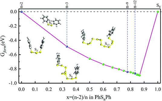 | ||
| Fig. 1 The Gform for PhSnPh (1 ≤ n ≤ 15), the inset show the optimized stable structures of PhSPh, PhS2Ph, PhS3Ph, PhS9Ph and PhS12Ph, respectively. | ||
3. Results and discussion
3.1 PhSnPh molecules
Firstly, the structures of PhSnPh molecules are optimized without considering the solvent effect. After completely optimized, phenyl groups are at both ends, and sulfur atoms are chain-like between the two phenyl groups. The bond lengths, bond angles of S–S bonds and S–Ph bonds, and dihedral angles of phenyls are listed in Table 1. The S–S bond lengths are in the interval of 2.04–2.09 Å and the interval of bond angles of S–S bonds are 107.48–110.26°, which in good agreement with the literature of Ralf Steude's review about the chain-like structures of RSnR molecules.24 In Fig. 1, we show the optimized structural configures of PhSnPh molecules, the S–S bonds between two benzene ring screw around in the range of 320–330°, close to 360°, so the two phenyl groups nearly symmetric at n = 3, 6, 9, 12. This feature can also be verified from the dihedral angles. The dihedral angles of PhS3Ph, PhS6Ph, PhS9Ph, PhS12Ph are smaller, which are 1.38°, 40.32°, 26.74° and 16.77°, respectively.| Bond length dSS (Å) | Bond angle αSSS (deg) | Dihedral angle γPh (deg) | Bond length dSPh (Å) | Bond angle αSSPh (deg) | |
|---|---|---|---|---|---|
| PhSPh | — | — | 3.36 | 1.78 | 140.37 |
| PhS2Ph | 2.04 | — | 47.79 | 1.79 | 107.02–107.04 |
| PhS3Ph | 2.07–2.08 | 109.75 | 1.38 | 1.79 | 105.56–106.25 |
| PhS4Ph | 2.08 | 109.12–109.29 | 77.14 | 1.78 | 104.64–105.04 |
| PhS5Ph | 2.07–2.08 | 108.62–108.64 | 128.76 | 1.78 | 104.55–105.31 |
| PhS6Ph | 2.07–2.08 | 108.58–108.96 | 40.32 | 1.78 | 104.60–105.02 |
| PhS7Ph | 2.07–2.08 | 108.31–109.58 | 128.13 | 1.79 | 105.07–105.74 |
| PhS8Ph | 2.07–2.09 | 107.88–109.63 | 146.72 | 1.78 | 104.76–105.70 |
| PhS9Ph | 2.07–2.08 | 108.01–109.19 | 26.74 | 1.78 | 104.69–105.12 |
| PhS10Ph | 2.07–2.09 | 107.78–110.26 | 136.86 | 1.78 | 105.08–107.20 |
| PhS11Ph | 2.07–2.09 | 107.51–110.15 | 80.13 | 1.78 | 104.75–105.13 |
| PhS12Ph | 2.07–2.09 | 107.48–110.07 | 16.77 | 1.78 | 104.67–105.05 |
To compare some useful information with in situ and operando experiments, we simulated ultraviolet-visible (UV-vis) spectroscopy. As shown in Fig. 2(a), there is only one peak among the ultraviolet range (200–700 nm) for different phenyl polysulfides; the peak wavelength (λ, in nm) increase with the number of S atom (n) and convergence at the PhS6Ph. Only considering the PhS2Ph, PhS4Ph, PhS5Ph and PhS6Ph, the curve of peak λ behave almost linear strand, which is in good agree with the experiment dates.17 When n (number of sulfur atoms) is an integer multiple of 3 (n = 3, 6, 9 and 12), the peak λ behaves a bigger bathochromic shift which are shown with red dots in Fig. 2(b). The peak wavelengths are derived from the out-of-plane deformation of the phenyl rings due to the polysulfide linkages.25 According to the structure configures shown in inset Fig. 1, the sulfur atoms between two phenyls are chain-like and present a spiral, three sulfur atoms form a unit; when there are integer units in the linkages (n = 3, 6, 9 and 12), the dihedral angles are smaller, the structure configures of PhS3Ph, PhS6Ph, PhS9Ph, PhS12Ph show more symmetric and behave more stable. The characteristics of the above-mentioned UV-vis spectroscopy of PhSnPh could be used to identify the synthesized polysulfides in experiments.
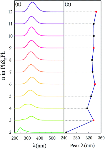 | ||
| Fig. 2 (a) Simulated UV-vis spectra and (b) the peak λ in UV-vis spectra of the PhSnPh (2 ≤ n ≤ 12) molecules. | ||
3.2 Average voltage and specific energy of PhSnPh cathodes
In order to calculate the average voltages of PhSnPh cathodes, the implicit solvent model (PCM) was used to describe the interaction between PhSnPh and the electrolyte. Both in experiment26 and calculation,27 1,2-dimethoxyethane (DME) and 1,3-dioxolane (DOL) are the electrolytes widely used in lithium–sulfur batteries at present. With DME/DOL (1![[thin space (1/6-em)]](https://www.rsc.org/images/entities/char_2009.gif) :
:![[thin space (1/6-em)]](https://www.rsc.org/images/entities/char_2009.gif) 1, v/v), the theoretical voltage of polysulfides is quite close to the experimental voltage of 2.0–2.6 V.28,29 Therefore, in the following research, all calculation consider solvation effect of DME/DOL (1
1, v/v), the theoretical voltage of polysulfides is quite close to the experimental voltage of 2.0–2.6 V.28,29 Therefore, in the following research, all calculation consider solvation effect of DME/DOL (1![[thin space (1/6-em)]](https://www.rsc.org/images/entities/char_2009.gif) :
:![[thin space (1/6-em)]](https://www.rsc.org/images/entities/char_2009.gif) 1, v/v) to make our results more reasonable and close to reality. We calculate average voltages according to the average energy changes of full lithiation processes.30 The process of full lithiation can be expressed as:
1, v/v) to make our results more reasonable and close to reality. We calculate average voltages according to the average energy changes of full lithiation processes.30 The process of full lithiation can be expressed as:| PhSnPh + (2n − 2)Li = 2PhSLi + (n − 2)Li2S | (2) |
| Gave = [2GPhSLi + (n − 2)GLi2S − GPhSnPh − (2n − 2)GLi]/(2n − 2) | (3) |
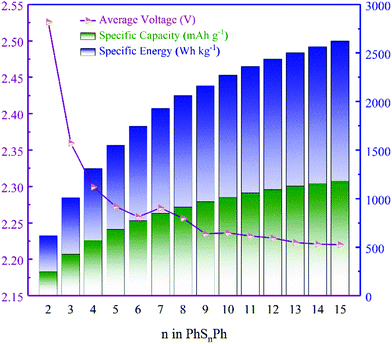
Note that, not existing originally in the anode, the Gibbs free energy here for Li is electrolyte-free. The average voltages of PhSnPh cathodes are shown in Fig. 3, as well as the discharge specific capacity and specific energy.
From Fig. 3, the average voltages first reduce quickly as n increases in PhSnPh, and then approach to 2.227 V when n ≥ 9. Next, we analyze the discharge specific capacities and specific energies. With the increasing of S atoms, they keep rising. The specific energy of PhS15Ph, 2632 W h kg−1, reaches the theoretical value of S8, 2600 W h kg−1.31 And its specific capacity is up to 1182 mA h g−1, nearly five times that of state-of-the-art cathode materials used in Li-ion batteries.32 The comparison of theoretical specific capacities and energies clearly indicate the great promise PhSnPh hold in surpassing the current cathode materials used in Li-ion batteries.
3.3 The discharge lithiation process of PhSnPh cathodes
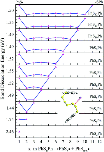
Here we propose the bond dissociation energy (BDE) as another method to analysis the lithiation. BDE, also called bond dissociation enthalpy, is the most effective quantitative description of chemical bonds,33 It is defined as the change in reaction enthalpy of the breaking process of chemical bonds, that is, BDEs are investigated by the density functional theory.34 In this way, DFT can predict excellent results for these energies.35 The sum of electronic and thermal enthalpies of PhSnPh, and
and  are calculated to determine the dissociation energies of the bonds. BDEs are all positive because the bonds need to absorb energies to dissociate. In other words, it's easier for bonds to break where the dissociation energy is lower. M. J. Bausch et al. has estimated S–S BDE of phenyl disulfide. Literature data indicates that the gas-phase BDE for the S–S bonds in PhSSPh is about 55 kcal mol−1, 2.31 eV.36 With the method above, S–S BDE of PhS2Ph in DME/DOL (1
![[thin space (1/6-em)]](https://www.rsc.org/images/entities/char_2009.gif) :
:![[thin space (1/6-em)]](https://www.rsc.org/images/entities/char_2009.gif) 1, v/v) is 2.46 eV. It is a little bigger than that of gas-phase because of different states. But they are very consistent and enough to demonstrate that our calculation is reliable.
1, v/v) is 2.46 eV. It is a little bigger than that of gas-phase because of different states. But they are very consistent and enough to demonstrate that our calculation is reliable.
According to Fig. 4, the first step of lithiation may react at the second S–S bond or the penultimate one, which can be described equally as:
 | (4) |
 | (5) |
In judging the strength of a bond in a chemical reaction, we should also consider the stability of free radicals after dissociation. Since the free radicals would directly generate PhSnLi with Li+, the stability of the  can be measured by the Gibbs formation energies of PhSnLi. We also use an “alloy-like” diagram to analyze the optimized molecules. We get the formation energies based on this equation:
| Gform = [GPhSnLi − (n − 1)GS8/8−GPhSLi]/n | (6) |
As it is shown in Fig. 5, long-chain PhSnLi (n ≥ 3) is more stable than PhS2Li with lower Gibbs formation energy. So in the first step of lithiation, only one bond would dissociate to form PhS2Li and PhSn−2Li. Concern is that there is no Li2Sn in this reaction:
| PhSnPh + 2Li = PhS2Li + PhSn−2Li | (7) |
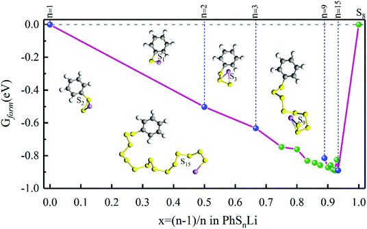 | ||
| Fig. 5 The Gform for PhSnLi. The insets show the optimized stable structures of PhSLi, PhS2Li, PhS3Li, PhS9Li and PhS15Li, respectively. | ||
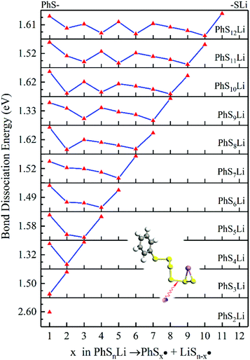
We use the same ways to analysis the subsequent lithiation of PhSnLi, shown in Fig. 6. The lower position of dissociation energy of S–S bond increases with the increase of n. But considering better stability of long-chain PhSnLi (n ≥ 3), the lithiation of PhSnLi would react at the penultimate S–S bond to generate PhSn−2Li and Li2S2 (n ≥ 3) or Li2S (n = 2). The latter lithiations will follow this pattern until they are completely reduced into PhSLi and Li2S.
In conclusion, at the beginning of the discharge, PhSnPh is reduced to PhS2Li and PhSn−2Li. With the depth of discharge increasing, PhSn−4Ph, PhSn−6Ph, PhSn−8Ph and other intermediate products (PhSxLi) are generated in sequence. Meanwhile, Li2S2 is formed. Finally, PhS2Li is further reduced to PhSLi and Li2S. Li2S2 is deoxidized into Li2S. This chemical change can be expressed by four steps:
| PhSnPh + 2Li = PhS2Li + PhSn−2Li | (R1) |
| PhSxLi + 2Li = PhSx−2Li + Li2S2 | (R2) |
 | (R3) |
In this discharge sequence, the reaction energies (Grec) can be calculated with the energy difference between the reactants and the products. Based on reaction energies, the corresponding voltages versus Li/Li+ are listed in Table S1.† Fig. 7(a) shows calculated reaction sequences of PhS5Ph. PhS5Ph may break the S–S bond and form PhS3Li and PhS2Li when attracted by Li+ and e− firstly. During the step of discharge, the reaction energy is 5.05 eV and the voltage is 2.53 V. Then PhS3Li will take another Li+ and e− to generate PhS2Li with 2.52 V. The final step is that PhS2Li and Li2S2 are reduced into PhSLi and Li2S, respectively. The two reactions can be regarded as the final step of the whole lithiation and the average voltage is 2.04 V. The voltage profiles of the entire discharge process are mostly consistent with the experiments.17
 | ||
| Fig. 7 (a) Schematic illustration of the discharge process of the PhS5Ph cathode; (b) relaxed structure of PhS5Ph + Li, the difference map of electron density between S and Li are also shown. | ||
To reveal the structure change of PhSnPh when attacked by a Li+ and a e−, we take PhS5Ph for example to draw the difference map of electron density. In Fig. 7(b), red solid lines and blue dashed lines correspond to the regions having increased electron density and decreased electron density during the process, respectively. Obviously, the S2–S3 bond is weakened sharply and the Li+ is bonded to S3. Furthermore, the S2–S3 bond distance increase from 2.08 Å to 3.19 Å. PhS5Ph molecule splits up to form PhS3Li and  radical, the latter of which will further obtain a Li+ and a e− to form PhS2Li. The result is the same with the first lithiation step derived from BDE. For this reason, it also proves that our method of analyzing the lithiation steps by BDE is reliable.
The discharge order of PhS10Ph is shown in Table 2. In the first step, PhS10Ph is reduced to PhS2Li and PhS8Li at 2.68 V. As the discharge depth increases, PhS8Li is reduced to PhS6Li, PhS4Li and PhS2Li in sequence with voltages of 2.52 V, 2.46 V and 2.47 V, respectively. Finally, PhS2Li and Li2S2 are reduced into PhSLi and Li2S at an average voltage of 2.04 V. The voltage prediction will be of great value in the research of PhSnPh as cathodes for Li–S batteries.
| Label | Category | Reactions | Grec (eV) | Voltage (V) | Feasibility |
|---|---|---|---|---|---|
| R1 | PhS5Ph | PhS5Ph + 2Li = PhS2Li + PhS3Li | −5.05 | 2.53 | ✓ |
| R2 | PhS3Li + 2Li = PhSLi + Li2S2 | −5.03 | 2.52 | ✓ | |
| R3 | PhS2Li + 2Li = PhSLi + Li2S | −4.36 | 2.18 | ✓ | |
| R3 | Li2S2 + 2Li = 2Li2S | −3.80 | 1.90 | ✓ | |
| R1 | PhS10Ph | PhS10Ph + 2Li = PhS2Li + PhS8Li | −5.36 | 2.68 | ✓ |
| R2 | PhS8Li + 2Li = PhS6Li + Li2S2 | −5.04 | 2.52 | ✓ | |
| R2 | PhS6Li + 2Li = PhS4Li + Li2S2 | −4.92 | 2.46 | ✓ | |
| R2 | PhS4Li + 2Li = PhS2Li + Li2S2 | −4.94 | 2.47 | ✓ | |
| R3 | PhS2Li + 2Li = PhSLi + Li2S | −4.36 | 2.18 | ✓ | |
| R3 | Li2S2 + 2Li = 2Li2S | −3.80 | 1.90 | ✓ |
In the whole discharge process, there is no Li2S4, Li2S6, Li2S8. To compare the dissolution of PhSnLi and Li2Sn (n = 4, 6, 8) in the DOL/DME solvent, the dissolving free energies37 of them with the solvent effect of DOL/DME (1![[thin space (1/6-em)]](https://www.rsc.org/images/entities/char_2009.gif) :
:![[thin space (1/6-em)]](https://www.rsc.org/images/entities/char_2009.gif) 1, v/v) are calculated. As shown in Fig. S1,† the dissolving free energies of PhSnLi (1 ≤ n ≤ 13) are almost above those of Li2Sn (n = 4, 6, 8) which result in shuttle effect. Therefore, the solubilities of PhSnLi (1 ≤ n ≤ 13) are lower and the shuttle effect causes by PhSnLi is much weaker than that by Li2Sn (n = 4, 6, 8). We take it that the excellent stability of long-chain PhSnLi and the dissociation positions of S–S bonds jointly contribute to such a result. Here, it can be considered that phenyl plays a certain role in fixing soluble polysulfide, preventing polysulfide from being dissolved into the electrolyte, which can greatly slow down the “shuttle effect”. This is beneficial to improve coulomb efficiency and capacity attenuation, and achieve better cycle stability and energy efficiency in practical applications. Until now, there are some ways to eliminate the “shuttle effect” particularly: improve the electrolyte performance,38 recombine cathodes with organic polymers39 or porous materials40 and so on. In comparison to these ways, the synthesis of PhS15Ph is more facile and available. So this class of cathode materials is of great research significance and potential for LSBs.
1, v/v) are calculated. As shown in Fig. S1,† the dissolving free energies of PhSnLi (1 ≤ n ≤ 13) are almost above those of Li2Sn (n = 4, 6, 8) which result in shuttle effect. Therefore, the solubilities of PhSnLi (1 ≤ n ≤ 13) are lower and the shuttle effect causes by PhSnLi is much weaker than that by Li2Sn (n = 4, 6, 8). We take it that the excellent stability of long-chain PhSnLi and the dissociation positions of S–S bonds jointly contribute to such a result. Here, it can be considered that phenyl plays a certain role in fixing soluble polysulfide, preventing polysulfide from being dissolved into the electrolyte, which can greatly slow down the “shuttle effect”. This is beneficial to improve coulomb efficiency and capacity attenuation, and achieve better cycle stability and energy efficiency in practical applications. Until now, there are some ways to eliminate the “shuttle effect” particularly: improve the electrolyte performance,38 recombine cathodes with organic polymers39 or porous materials40 and so on. In comparison to these ways, the synthesis of PhS15Ph is more facile and available. So this class of cathode materials is of great research significance and potential for LSBs.
4. Summary
In conclusion, using the ab initio density functional theory calculation, we have performed thorough theoretical studies for diphenyl polysulfides as cathode materials for LSBs. One goal is to increase the sulfur proportion in PhSnPh compounds, more sulfur proportion means high specific capacity; the other goal is to overcome the “shuttle effect” challenge for the current LSBs, namely the dissolution of lithium polysulfide. Though the Gibbs free energy calculation and “alloy-like” diagram analysis, we found the PhSnPh molecules are thermodynamically stable, and the PhS15Ph behave almost the same energy density as S8, 2632 W h kg−1. By calculation the BDE of the PhSnPh cathode, we found that only short-chain polysulfides generate in the discharge process, PhSnPh prevents the formation of soluble long-chain intermediates that plague traditional sulfur cathodes. We hope that this work leads to further studies in experiment, which would make PhSnPh a promising candidate for low-cost, eco-friendly, and intrinsically safe cathode materials for applications in rechargeable lithium batteries.There are other aspects which we haven't discussed until now, most importantly, the volumetric capacity. One cannot get high volumetric capacity by using only one PhSnPh molecule, a possible solution might include the use of PhSnPh molecule to establish unit cell of 3D frameworks,41 but poor conductivity is a very big defect. Recently, Se is introduced into S cathodes by forming Se–S bonds to modify the electronic and ionic conductivity and ultimately enhance cathode utilization in LSBs,42,43 this is also the topic we need to study next.
Conflicts of interest
There are no conflicts to declare.Acknowledgements
JBW was supported by the National Natural Science Foundation of China (No. 11047164), the Shanghai College Foundation for Excellent Young Teachers of China (No. gjd10023) and the Academic Program of Shanghai Municipal Education Commission (No. 11XK11 and 2011X34).References
- A. Manthiram, S. H. Chung and C. X. Zu, Adv. Mater., 2015, 27, 1980–2006 CrossRef CAS.
- Y. Diao, K. Xie, S. Z. Xiong and X. B. Hong, J. Power Sources, 2013, 235, 181–186 CrossRef CAS.
- W. Chen, T. Lei, C. Wu, M. Deng, C. Gong, K. Hu, Y. Ma, L. Dai, W. Lv, W. He, X. Liu, J. Xiong and C. Yan, Adv. Energy Mater., 2018, 8, 1702348 CrossRef.
- Y. B. He, Y. Qiao and H. S. Zhou, Dalton Trans., 2018, 47, 6881–6887 RSC.
- K. Yang, S. N. Zhang, D. M. Han, M. Xiao, S. J. Wang and Y. Z. Meng, Prog. Chem., 2018, 30, 1942–1959 Search PubMed.
- V. Knap, D. I. Stroe, M. Swierczynski, R. Teodorescu and E. Schaltz, J. Electrochem. Soc., 2016, 163, A911–A916 CrossRef CAS.
- A. Fotouhi, D. Auger, L. O'Neill, T. Cleaver and S. Walus, Energies, 2017, 10, 1937 CrossRef.
- A. Manthiram, Y. Z. Fu and Y. S. Su, Acc. Chem. Res., 2013, 46, 1125–1134 CrossRef CAS.
- W. Chen, T. Lei, T. Qian, W. Lv, W. He, C. Wu, X. Liu, J. Liu, B. Chen, C. Yan and J. Xiong, Adv. Energy Mater., 2018, 8, 1702889 CrossRef.
- T. Lei, W. Chen, W. Lv, J. Huang, J. Zhu, J. Chu, C. Yan, C. Wu, Y. Yan, W. He, J. Xiong, Y. Li, C. Yan, J. B. Goodenough and X. Duan, Joule, 2019, 3, 2091–2104 CrossRef.
- A. Bhargav, S. V. Patil and Y. Fu, Sustainable Energy Fuels, 2017, 1, 1007–1012 RSC.
- X. Liang, C. Hart, Q. Pang, A. Garsuch, T. Weiss and L. F. Nazar, Nat. Commun., 2015, 6, 8 Search PubMed.
- T.-G. Jeong, Y.-S. Lee, B. W. Cho, Y.-T. Kim, H.-G. Jung and K. Y. Chung, J. Alloys Compd., 2018, 742, 868–876 CrossRef CAS.
- J. Zheng, G. Ji, X. Fan, J. Chen, Q. Li, H. Wang, Y. Yang, K. C. DeMella, S. R. Raghavan and C. Wang, Adv. Energy Mater., 2019, 16, 1803774 CrossRef.
- T. Lei, W. Chen, Y. Hu, W. Lv, X. Lv, Y. Yan, J. Huang, Y. Jiao, J. Chu, C. Yan, C. Wu, Q. Li, W. He and J. Xiong, Adv. Energy Mater., 2018, 8, 1802441 CrossRef.
- M. Wu, A. Bhargav, Y. Cui, A. Siegel, M. Agarwal, Y. Ma and Y. Z. Fu, ACS Energy Lett., 2016, 1, 1221–1226 CrossRef CAS.
- A. Bhargav, M. E. Bell, J. Karty, Y. Cui and Y. Fu, ACS Appl. Mater. Interfaces, 2018, 10, 21084–21090 CrossRef CAS PubMed.
- W. Chen, T. Lei, W. Lv, Y. Hu, Y. Yan, Y. Jiao, W. He, Z. Li, C. Yan and J. Xiong, Adv. Mater., 2018, 40, e1804084 CrossRef.
- Y. C. Qiu, W. F. Li, W. Zhao, G. Z. Li, Y. Hou, M. N. Liu, L. S. Zhou, F. M. Ye, H. F. Li, Z. H. Wei, S. H. Yang, W. H. Duan, Y. F. Ye, J. H. Guo and Y. G. Zhang, Nano Lett., 2014, 14, 4821–4827 CrossRef CAS.
- P. Adelhelm, P. Hartmann, C. L. Bender, M. Busche, C. Eufinger and J. Janek, Beilstein J. Nanotechnol., 2015, 6, 1016–1055 CrossRef CAS.
- D. Larcher and J. M. Tarascon, Nat. Chem., 2015, 7, 19–29 CrossRef CAS PubMed.
- N. Nitta, F. X. Wu, J. T. Lee and G. Yushin, Mater. Today, 2015, 18, 252–264 CrossRef CAS.
- J. B. Wu and L. W. Wang, J. Mater. Chem. A, 2018, 6, 2984–2994 RSC.
- R. Steudel, Chem. Rev., 2002, 102, 3905–3945 CrossRef CAS.
- H. J. Peng, J. Q. Huang, X. B. Cheng and Q. Zhang, Adv. Energy Mater., 2017, 7, 54 Search PubMed.
- S. S. Zhang, J. Power Sources, 2013, 231, 153–162 CrossRef CAS.
- L. J. Wang, T. R. Zhang, S. Q. Yang, F. Y. Cheng, J. Liang and J. Chen, J. Energy Chem., 2013, 22, 72–77 CrossRef CAS.
- J. Hassoun, Y.-K. Sun and B. Scrosati, J. Power Sources, 2011, 196, 343–348 CrossRef CAS.
- M. Yao, H. Ando and T. Kiyobayashi, Energy Procedia, 2016, 89, 222–230 CrossRef CAS.
- Z. Lan, M. Chen, X. Xu, C. Xiao, F. Wang, Y. Wang, Y. Lu, Y. Jiang and J. Jiang, J. Alloys Compd., 2017, 701, 875–881 CrossRef CAS.
- X. L. Ji and L. F. Nazar, J. Mater. Chem., 2010, 20, 9821–9826 RSC.
- X. Liu, B. K. Li, L. Yao, P. B. Wang, X. H. Kong and Y. F. Zhang, J. Nanosci. Nanotechnol., 2019, 19, 4052–4057 CrossRef.
- B. Kalimuthu, N. Muralidharan and K. Nallathamby, J. Alloys Compd., 2019, 780, 177–185 CrossRef CAS.
- J. M. Hudzik and J. W. Bozzelli, J. Phys. Chem. A, 2012, 116, 5707–5722 CrossRef CAS.
- D. Julian, in 3rd International Seminar on Chemistry 2014, ed. H. Hayashi, R. Read and K. Awang, Elsevier Science Bv, Amsterdam, 2015, vol. 17, pp. 99–105 Search PubMed.
- C. G.-F. M. J. Bausch and R. Gostowski, Energy Fuels, 1991, 3, 419–423 CrossRef.
- R. F. Ribeiro, A. V. Marenich, C. J. Cramer and D. G. Truhlar, J. Phys. Chem. B, 2011, 115, 14556–14562 CrossRef CAS PubMed.
- L. Wang, Y. Ye, N. Chen, Y. Huang, L. Li, F. Wu and R. Chen, Adv. Funct. Mater., 2018, 28, 1800919 CrossRef.
- J. Z. Zhen Li, Y. Lu and X. W. Lou, Sci. Adv., 2018, 6, eaat1687 Search PubMed.
- G. Ma, Z. Wen, J. Jin, Y. Lu, X. Wu, M. Wu and C. Chen, J. Mater. Chem. A, 2014, 2, 10350–10354 RSC.
- W. Guo, A. Bhargav, J. D. Ackerson, Y. Cui, Y. Ma and Y. Fu, Chem. Commun., 2018, 54, 8873–8876 RSC.
- J. Zhou, T. Qian, N. Xu, M. Wang, X. Ni, X. Liu, X. Shen and C. Yan, Adv. Mater., 2017, 33, 1701294 CrossRef.
- X. Li, J. Liang, J. Luo, C. Wang, X. Li, Q. Sun, R. Li, L. Zhang, R. Yang, S. Lu, H. Huang and X. Sun, Adv. Mater., 2019, 17, e1808100 CrossRef.
Footnote |
| † Electronic supplementary information (ESI) available. See DOI: 10.1039/c9ra06402h |
| This journal is © The Royal Society of Chemistry 2019 |

