 Open Access Article
Inherent mechanical properties of bilayer germanene coupled by covalent bonding†
Mahmuda Raakib Arshee,
Saqeeb Adnan,
Mohammad Motalab * and
Pritom Bose
Department of Mechanical Engineering, Bangladesh University of Engineering and Technology, Dhaka-1205, Bangladesh. E-mail: abdulmotalab@me.buet.ac.bd
First published on 25th October 2019
Abstract
Germanene, a two-dimensional buckled hexagonal structure of germanium atoms, has attractive mechanical, optical, thermal and electronic features. Recently it has been reported that covalent bonding between two monolayer germanene sheets leads to the integration of intrinsic magnetism and band gap opening that makes it attractive to future nanoelectronics. In order to use the captivating features of this structure, its mechanical characterization needs to be studied. In this study, molecular dynamics simulations have been performed using optimized Tersoff potential to analyze the effect of chirality, temperature and strain rate on the uniaxial tensile properties of this structure. This study suggests that bonded bilayer germanene shows higher mechanical strength compared to monolayer germanene. Uniaxial loading in the armchair direction shows higher fracture strength and strain compared to the zigzag direction which is contrary to the monolayer germanene. It also reports that with increasing temperature, both the fracture strength and strain of the structure decrease. It has been found that at a higher strain rate, the material exhibits higher fracture strength and strain. Mechanical properties and fracture mechanisms of defected structures have also been reported below the curie temperature. Moreover, the interlayer shear characteristics of the bilayer structure have been looked into. These results will provide significant insight to the investigation of this structure as a potential nano-electronics substitute.
1. Introduction
Graphene, a single atom thick planar hexagonal array of sp2 bonded carbon atoms, attracted immense interest among researchers due to its novel mechanical,1–4 electrical5–7 and other physical8,9 properties that have made it the most extensively studied two-dimensional material. The discovery of graphene paved the way for the discovery of other members of group-IV elemental 2D atomic-layer systems including silicene, germanene and stanene.Germanene, the graphene based analogue of germanium, was predicted to exist and have a stable, two-dimensional, low-buckled, honeycomb structure in 2009.10 Synthesis of free standing germanene has not yet been achieved. At first, the hydrogenated partner of germanene (germanane) was synthesized by wet chemistry starting from solid calcium digermanide (CaGe2),11 which was then stabilized by methyl replacement of the H termination.12 Synthesis of germanene on a Pt surface was first reported by Li, et al.13 Nearly at the same time, germanene had also been grown by dry deposition of germanium onto Au surface14 followed by growth of continuous germanene layer on Al reported by Derivaz et al.15 Recently it has been shown that few layer germanene grown on Au, allows reduced interaction resulting in better Dirac fermion characteristics compared to monolayer germanene.16
Unlike graphene, the energy needed to hybridize p orbitals is much less in free standing germanene, and also due to the Ge–Ge bond being much larger than C–C bond, weak overlapping between the pz orbitals make pi bond formation difficult in germanene. So, mixed sp2 and sp3 hybridization leads to a buckled structure.17–19
Despite having remarkable properties, the integration of graphene in the current Si and Ge based technology seems to be challenging compared to silicene and germanene.20 Another advantage both silicene and germanene have over graphene is due to the buckled structure that makes it possible to open a tunable bandgap by vertical electric field.21 The potential optical and optoelectronic applications22,23 predicted robust 2D topological insulator character nearly up to room temperature resulting from the large effective spin–orbit coupling,24 opening the way to the quantum spin Hall effect,25,26 the possibility of very high Tc superconductivity,27 suitability of being anode material in Na and Li-ion batteries28 all make germanene a potent 2D material.
A recent study done by Wang et al.29 revealed that intrinsic magnetism and band gap opening can be simultaneously achieved in 2D bilayer silicene and germanene system if strong covalent interlayer bonds are established. The bonds break the original pi bonding network within each layer leaving localized and unpaired electrons that are able to carry magnetic moments. So, presence of interlayer bonds can turn nonmagnetic germanene sheets into infinite magnetic sheets where the atoms couple ferromagnetically within each layer while antiferromagnetically between two layers with an estimated curie temperature of 33 K which is much lower than room temperature. Many potential applications of the bilayer bonded germanene structure shown in this study can be realized in future nanoelectronics, spin-based computation and data storage.
A study done by Sharma et al. suggested that adsorption of Li atoms at hollow sites of this structure is energetically favorable and it can serve as a prospective anode material for Li-ion batteries.30 Although a number of studies have been performed on the mechanical,31,32 electrical,20,33 optical34 and magnetic35,36 properties of single layer germanene and magnetic29 properties of bilayer germanene, there is hardly any research found on the mechanical properties of bilayer bonded germanene structure (BBGS). The study of mechanical properties of this BBGS under various loading conditions is critical in order to utilize this material in designing electronic components. This work aims to explore the mechanical properties of this structure with the help of Molecular Dynamics (MD) using optimized Tersoff potential. MD is a simulation method that has been applied by many researchers effectively to investigate mechanical properties of two-dimensional materials.37–40
In this study the effect of tensile loading along the armchair and zigzag directions at different temperatures have been investigated and compared with the single layer germanene structure. Effect of various strain rates have also been studied. As exfoliation is the only synthesis process of germanene so far, structural defects like vacancies and Stone–Thrower–Wales (SW) are common in germanene. Presence of these defects enables germanene to sense gas molecules.41 In this study the effect of defects on material strength at a temperature below the curie temperature has also been reported.
Interlayer shear between germanene sheets plays an important role in germanene-based materials and devices. To shed light on the interlayer shear mechanism between germanene sheets, the interlayer shear characteristics subjected to pulling force along both the armchair and zigzag directions have been studied.
2. Methodology
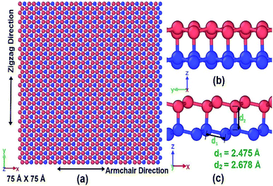
To investigate the mechanical properties of bonded bilayer germanene sheets MD simulations have been performed in Large-scale Atomic/Molecular Massively Parallel Simulator (LAMMPS).42 The simulation model used in this study is shown in Fig. 1. This simulation model has previously been used to investigate magnetic property and band gap opening of bilayer germanene29 and also to investigate the suitability of bi-layer germanene for Li absorption.30 The intra-layer and inter-layer bond lengths are 2.475 Å and 2.678 Å respectively. The covalent interlayer bonds in the BBGS are generated by moving the bottommost atom of the buckled top layer and the topmost atom of the buckled bottom layer to the bond distance forming AB stacking configuration. The armchair and zigzag directions of the BBGS are oriented along the X and Y axes, respectively. Periodic boundary conditions are applied in both the X and Y directions to reduce the finite length effect, while a sufficiently large vacuum depth of 35 Å is applied on both sides in Z direction in order to decouple the periodic images. The dimension of the model is 75 Å × 75 Å consisting of 1440 atoms. This size has been chosen because all the mechanical properties of the bilayer model converge with this size as the size of the model is gradually increased from 46 Å × 47 Å under periodic boundary condition (details of the effect of size are in Section 1 of ESI†).To define atomic interactions, optimized Tersoff potential parameters for germanene have been used.19,43 In Tersoff potential, cutoff function is found to overestimate the maximum force needed to break an interatomic bond.44 Previous studies32,45 indicate that it consequently contributes to the overestimation of stress and strain. In order to prevent this anomalous overestimation, the small cutoff is decreased and the large cutoff is increased. The optimized parameters used in this study are listed in Table 1. (Details of the optimized potential parameters are in Section 2 of ESI†). The results indicate that this atomic potential maintains the initial buckled structure of germanene in both layers (Fig. 2) during the structure relaxation and equilibrium.
| A = 1760.1 eV | B = 415.0 eV | λ1 = 2.4451 Å−1 | m = 3 |
| λ2 = 1.71 Å−1 | λ3 = 0.000 Å−1 | n = 0.75627 | λijk = 1 |
C = 106![[thin space (1/6-em)]](https://www.rsc.org/images/entities/char_2009.gif) 430 430 |
β = 5.017 × 10⁻⁷ | d = 15.2 | |
cos![[thin space (1/6-em)]](https://www.rsc.org/images/entities/char_2009.gif) θ0 = −0.35 θ0 = −0.35 |
R = 2.95 Å | D = 1.25 Å |
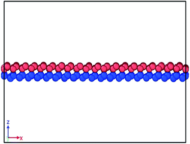 | ||
| Fig. 2 Snapshot of bilayer bonded germanene after energy, pressure and thermal equilibration. The structure is seen well relaxed and the buckled form remains true. | ||
The equations of atomic motion are integrated with a time step of 0.001 picosecond. Geometries are relaxed using conjugate gradient (cg) minimization scheme. After geometry relaxation, to equilibrate the system, equilibration simulations are performed using NVE (microcanonical ensemble) for 200 picoseconds. Then Pressure equilibration is performed for 200 picoseconds using NPT (isothermal isobaric ensemble) at a pressure of 1 bar. NPT simulation results in reconfiguration of the structure and removes internal stress developed. Subsequently, NVT (canonical ensemble) is executed for 100 picoseconds (ps) for thermal equilibrium.
The atomic stress values of each atom during deformation in the simulation system is calculated based on the definition of virial stress, which is expressed as46
 | (1) |
The summation is over all the atoms occupying total volume ΩTot, mα and vα denote the mass and velocity of atom α. rαβ is the distance between atoms α and β. The term dV/drαβ is the scalar of force exerted on atom α by atom β.
In order to simulate the tensile loading, the model structure is stretched in both armchair and zigzag directions. Temperature is varied from 25 K to 400 K at constant strain rate of 0.01 ps−1 to determine temperature dependency. The effects of loading direction and temperature have been compared with those of single layer germanene. Further strain rates of 0.001, 0.01, 0.02, 0.05 ps−1 are used to investigate strain rate dependency. Defective BBGS is subjected to uniaxial tensile loading at a constant temperature of 25 K and strain rate of 0.01 ps−1. Five different types of defects are investigated. First type is a mono-vacancy created by removing a single atom of the top layer while the second type corresponds to mono-vacancy defect in each layer of the structure.47 While creating mono-vacancy one atom approximately from the center of the sheet's layer is removed. Third type of defect is bi-vacancy in both layers where two adjacent atoms from each layer are removed. Two types of Stone walls (SW) defects are created on both layers. SW-1 defect is produced by rotating a horizontal intra-layer Ge–Ge bond by 90°, while in SW-2 defect an angular intralayer Ge–Ge bond is rotated by 90°.
Finally, behaviours of BBGS under shear loading is investigated by applying a displacement loading. Before doing so, the system is equilibrated at 5 K for 50 ps (following Wang S. et al.48) in which the bottom layer is totally fixed and the upper layer can move freely in the x and y directions. The top layer is then moved at a constant speed of 1.0 m s−1 with a time-step of 0.2 fs at 5 K in both armchair and zigzag directions.
Considering the equilibrium van der Waals interaction distance of 4.22 Å for germanene49 and an interlayer distance of 2.668 Å, an effective thickness of 6.898 Å is used in this study. Due to the buckled structure of germanene, the thickness in the germanene structure cannot be easily determined experimentally. This ambiguity for the thickness of mono-atomic crystal structures such as germanene and similarly silicene, graphene and carbon nanotubes has been discussed in previous studies.50–52 So, stresses and elastic moduli of the system are reported in force per unit length (GPa nm or N m−1) rather than force per unit area (Pa).50,52
3. Results and discussions
3.1. Methodology validation
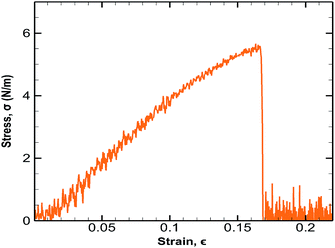
In order to validate the optimized Tersoff potential and computational results, MD simulations have been carried out on a monolayer germanene to determine its Young's modulus and ultimate tensile strength (UTS) in the armchair and zigzag directions. A monolayer germanene sheet containing 64 atoms is elongated in both armchair and zigzag directions at a strain rate of 0.003 ps−1 and at a temperature of 300 K.53 The computational results have been shown in Table 2 and the corresponding stress strain behaviour along the armchair direction has been depicted in Fig. 3.| References | 2D Ultimate tensile strength, N m−1 | Strain at maximal stress, % | 2D Young's modulus, N m−1 | |||
|---|---|---|---|---|---|---|
| Armchair | Zigzag | Armchair | Zigzag | Armchair | Zigzag | |
| Our calculation | 5.66 | 6.02 | 16.32 | 17.73 | 42.01 | 36.42 |
| Fracture study by Minh-Quy Le32 | 4.6 | 5.1 | 15.9 | 21.4 | 37.5 | 36 |
| DFT calculations by Mortazavi et al.53 | 4.7 | 4.1 | 20 | 20.5 | 44 | 43.4 |
| DFT calculations by Zhang and Wang54 | 41.4 | 41.4 | ||||
These results are in good agreement with previous studies.32,53,54 In order to eliminate stress overestimation, cutoff function is removed from the Tersoff potential in the study of Minh-Quy Le32 which is not done in this study leading to slightly higher values of strength.
The cohesive energy (eV per atom) is calculated to be 2.93 eV at 0.2 K which is in agreement with the values from previous studies by Kaloni (3.09 eV)55 and Minh-Quy Le (3.02 eV).32 The agreement of results also verifies the effectiveness of optimized Tersoff potential for germanene in the analysis of germanene based structures. All the results shown in the manuscript are subjected to statistical error of ∼1% in UTS, ∼2% in fracture strain and ∼0.05% in Young's modulus (details of error analysis are in Section 3 of the ESI†).
3.2 Effect of loading direction on fracture stress and strain
The bonded bilayer germanene structure has been stretched along both the armchair and zigzag directions at a constant strain rate of 0.01 ps−1 and at a constant temperature of 25 K to determine the material properties along both directions. In order to compare the result with bilayer germanene sheet, a single layer germanene sheet has been modelled and similar loading test has been performed in this case too as shown in Fig. 4.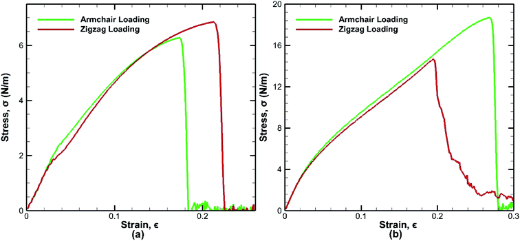 | ||
| Fig. 4 Stress strain curves for tensile loading test of (a) monolayer germanene sheet (b) bilayer germanene sheets at 25 K along both the armchair and zigzag directions. | ||
In case of bilayer germanene, the overall strength is found to increase due to the contribution of covalent bonding between the two layers. The strength increases from ∼6.28 N m−1 in single layer to ∼18.7 N m−1 in bilayer for armchair direction and from ∼6.85 N m−1 in single layer to ∼14.6 N m−1 in bilayer for zigzag direction. This finding is in agreement with previous study of Mahata et al. for single layer and bilayer stanene.56 The results reveal that in case of single layer germanene sheet, tensile strength along the zigzag direction is higher than that of the armchair direction, which is in accordance to the effect of chirality as found in previous studies of monolayer germanene31,32 and many other similar studies of graphene,57 silicene,39 stanene58 etc. However, the opposite effect is observed in case of bilayer germanene sheets, where tensile strength along the armchair direction is higher than that of the zigzag direction. Greater strength along the armchair direction than the zigzag direction has also been reported previously in the study of Mortazavi et al.53 in first principle investigation of germanene and also in the study of Mahata et al.56 in single and bi-layer stanene.
In single layer Ge sheet, when strain is applied along the zigzag direction, no chemical bond is parallel to the loading direction. The bond angles undergo deformation and suppress the elongation of the zigzag bonds. On the other hand, when armchair loading is applied, some bonds that are parallel to the loading direction get elongated easily and consequently break at a much lower strain. So, the fracture strain of monolayer sheet in the zigzag loading (∼22%) is much higher than that of the armchair loading (∼17%) as shown in Fig. 4(a).
However, different scenario occurs in the BBGS in case of armchair and zigzag loadings. In Fig. 5 and 6, the atomic configurations during both type of loading in BBGS are visually represented. The atoms in the bottom layer of the structure have been illustrated in red colour while the atoms in the upper layer have been illustrated with blue colour. In Fig. 5(a), the bond between a & b represents all the interlayer bonds and the bonds between a & c and a & d represent all the similar intralayer bonds. Atom marked with b is just beneath atom a and they share an interlayer bond.
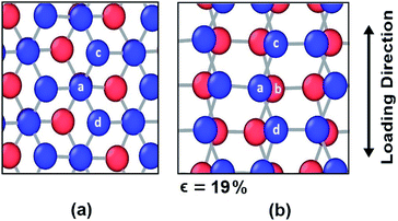 | ||
| Fig. 5 Atomic configuration (a) before application of strain (b) just before fracture in case of zigzag loading. | ||
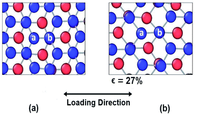 | ||
| Fig. 6 Atomic configuration (a) before application of strain (b) just before fracture in case of armchair loading. | ||
In case of zigzag loading in the BBGS, the deformation of bond angles gets hindered due to the presence of interlayer bonds. When loading is applied along the zigzag direction, bond angles of both layers corresponding to atoms a and b would tend to enlarge. They come to a position as shown in Fig. 5(b) just before fracture and the bond angle cannot deform any further. So, bond angle deformation is much lower here than in single layer Ge sheet. When further loading is applied, the bond a–c tends to elongate towards the loading direction but the interlayer bond a–b restricts the movement of a. This causes stress concentration and breakage of the bond a–c at a strain of about 19% at a temperature of 25 K whereas fracture strain of single layer sheet is ∼22%. So, in case of zigzag loading, the structure fails due to the rupture of intralayer bonds like a–c.
In case of armchair loading, it is observed from Fig. 6(a) and (b) that, the bond a–b and all the other similar horizontal intralayer bonds that are parallel to the loading direction get elongated. The interlayer bonds do not cause any hindrance in these elongations because both the layers get elongated equally and simultaneously. So, the bonds break at a fracture strain of about 27% at 25 K which is higher than that of zigzag loading.
3.3 Effect of temperature on mechanical properties
The mechanical properties of BBGS are investigated by performing simulations at different temperatures ranging from 25 K to 400 K. Uniaxial tensile loadings in both armchair and zigzag directions at a strain rate of 0.01 ps−1 have been applied. The obtained stress–strain curves at different temperatures are shown in Fig. 7. Temperature exerts strong effect on the fracture strength and fracture strain. An increase in temperature causes the ultimate strength and fracture strain of germanene sheet to decrease in both armchair and zigzag directions. This happens due to the increased mean distance between the atoms resulting from high atomic mobility.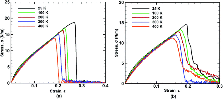 | ||
| Fig. 7 Stress strain curves of bonded bilayer germanene at different temperatures under tensile loading along (a) armchair and (b) zigzag directions. | ||
For instance, the ultimate tensile strength (∼13.9 N m−1) of the BBGS in armchair loading at 400 K is about 8% and 26% lower than those at room temperature (∼15.1 N m−1) and at 25 K (∼18.7 N m−1) respectively. While in zigzag loading the UTS (∼11.3 N m−1) at 400 K is about 7% and 23% lower than those at room temperature (∼12.1 N m−1) and at 25 K (∼14.6 N m−1) respectively. The fracture strain also reduces from ∼27% to ∼18% in armchair loading and ∼20% to ∼16% in zigzag loading in temperature range of 400 K to 25 K. The Young's modulus reduces by ∼22% (from ∼140.2 N m−1 at 25 K and ∼109.5 N m−1 at 400 K) in case of armchair loading and by ∼19% (from ∼133 N m−1 at 25 K and ∼108 N m−1 at 400 K) in case of zigzag loading. This finding is in accordance with the temperature dependency of UTS and fracture strain of pristine monolayer germanene,31 graphene,57 silicene.39 It is also observed that with the temperature rise, the ultimate strength, fracture strain and Young's modulus in armchair directional loading reduce more significantly compared to that of zigzag loading which is also consistent with previous studies.58
For armchair direction the fracture pattern is more brittle in nature than zigzag direction and no apparent plastic deformation is observed in the stress–strain curves. Sudden drops in the stress curves can be attributed to the major atomic rearrangement past the yield point of the BBGS. For zigzag loading, after going past the yield point, due to relative position of the two layers, there occurs an atomic rearrangement where the atoms that were previously non-bonded come close and form new bonds as shown in Fig. 8(a) and (b). These newly created bonds do not break abruptly. So, after the initiation of the first crack, the propagation of the crack gets hindered due to reconfigured structure which is shown in the darkened portion of Fig. 8(a) and (b). That is why the structure shows a ductile behaviour and the curves do not fall as sharply as in the case of armchair loading.
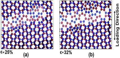 | ||
| Fig. 8 Atomic configuration past the yield strain (∼20%) at (a) 25% strain and (b) 32% strain in zigzag loading. | ||
A similar loading test has been performed for single layer germanene structure at the same strain rate and same range of temperatures to highlight the differences between the two structures as shown in Fig. 9. It is observed that the percentage of reduction in UTS, fracture strain and Young's modulus while decreasing temperature is more significant in case of bilayer structure than single layer structure. In case of single layer structure, the UTS reduces by ∼19% in zigzag direction and ∼16% in armchair direction, whereas in BBGS it reduces by ∼22% and ∼26% in these directions, respectively. In case of fracture strain, it is observed that fracture strain along the zigzag direction is higher in monolayer germanene than in bilayer germanene at all temperatures due to the geometrical imperfections created by the interlayer bonds that leads to reduction in fracture strain.56
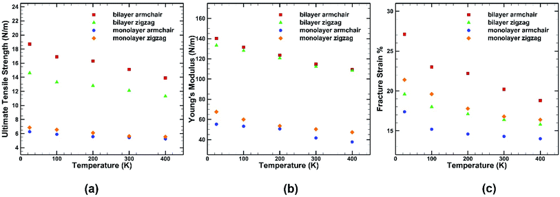 | ||
| Fig. 9 Effect of temperature on the (a) ultimate tensile strength (b) Young's modulus (c) fracture strain of both monolayer and bilayer germanene sheet. | ||
3.4 Effect of defects on mechanical properties
Different types of defects have been introduced in the BBGS system to investigate the mechanical properties of the defected systems at a temperature of 25 °C. The formation energies of all the defects have been reported in the study of Padilha et al. and it is observed that Stone Wales defect is most likely to occur in germanene as it has the lowest formation energy.59 The obtained stress–strain curves are shown in Fig. 10. It is revealed from the results that all the defected germanene structures have lower UTS and lower fracture strain compared to that of the pristine structures. Key observation here is that, presence of defect has less effect on the structure when it is subjected to zigzag loading.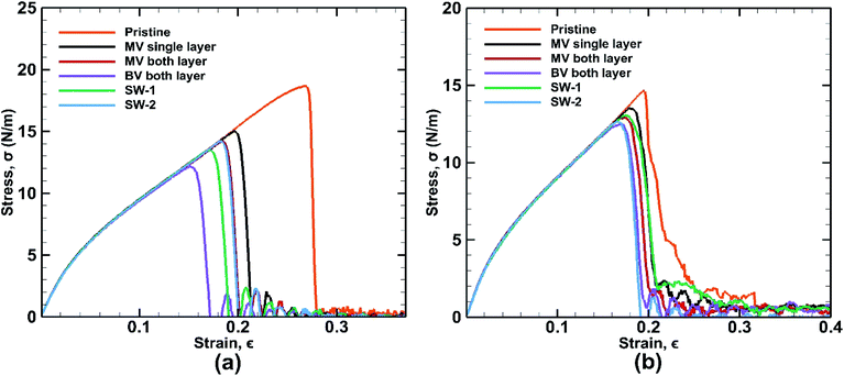 | ||
| Fig. 10 Stress strain curves for defected bonded bilayer germanene sheets in case of (a) armchair loading (b) zigzag loading at 25 K temperature. | ||
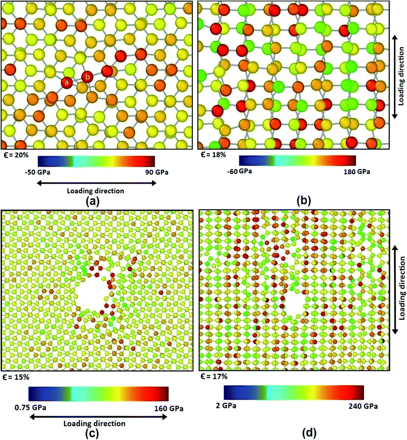
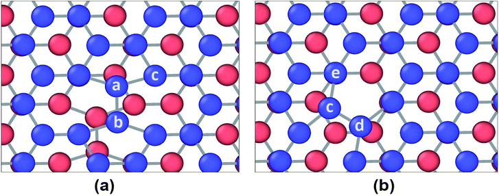
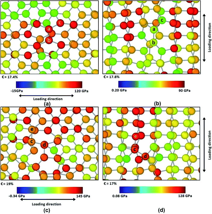
SW-1 defect has been created by 90-degree rotation of the bond a–b as shown in Fig. 12(a). From the figure it is observed that due to this defect, bond a–c and other similar bonds close to the defect become the largest bonds. All these bonds are more inclined towards the armchair direction and away from the zigzag direction. So, as shown in Fig. 13(a), when loading is applied along the armchair direction, stress concentration occurs in all the bonds close to the rotated bond. This is why the UTS is lower when SW-1 defect is present in bilayer bonded germanene structure.
Its observed from Fig. 13(b) that when loading is applied in the zigzag direction, stress concentration does not occur in the atoms near the rotated bonds, rather it occurs in the other atoms. So, effect of SW-1 defect is low here as in cases of other defects discussed earlier.
SW-2 defect has been created by 90-degree rotation of the bond c–d as shown in Fig. 12(b). From the figure it can be observed that due to this defect, the bond c–e and other similar bonds near the defect become the largest bonds. These bonds are pushed towards the zigzag direction and away from armchair direction. By noticing Fig. 13(c), it is observed that in case of armchair loading the defect is not causing that much stress concentration, so its effect is not very significant.
It is to be noted that SW-2 defect has the lowest effect in the tensile strength of the bilayer structure in case of armchair loading. In case of zigzag loading as shown in Fig. 13(d), stress concentration occurs near the defect unlike the case for SW-1 defect. So UTS is lower in case of SW-2 defect than SW-1 for zigzag loading.
3.5 Effect of strain rate on mechanical properties
The strain rate is an important factor affecting the mechanical properties of bonded bilayer germanene in the light of kinetic theory of solid fracture. The influence of different strain rates on stress strain curves is depicted along both the armchair and zigzag directions as shown in Fig. 14.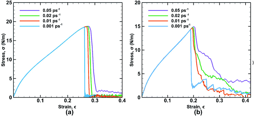 | ||
| Fig. 14 Stress strain curves of bonded bilayer germanene at different strain rate under tensile loading along (a) armchair and (b) zigzag directions at 25 K temperature. | ||
In case of armchair loading the UTS is increased by ∼1.4% from (∼18.5 N m−1 at 0.001 ps−1 to ∼18.76 N m−1 at 0.05 ps−1) and in case of zigzag loading the UTS is increased by ∼4.33% from (∼14.33 N m−1 at 0.001 ps−1 to ∼14.95 N m−1 at 0.05 ps−1). This is a common phenomenon because slower strain rate allows more time for the thermal fluctuation of atoms and therefore increasing the chance for the atoms to overcome the energy barrier required for breaking bonds. As a result, at higher strain rate material shows higher strength due to not getting sufficient time to break the bonds. However, compared to the temperature effect on the fracture strength, the strain rate effect is less significant in terms of magnitude. It is also observed that at higher strain rate, the zigzag loading direction shows ductile failure due to atomic reconfiguration beyond yield point.
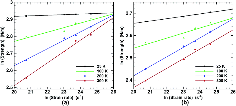
Effect of strain rate on fracture strength at different temperatures for both armchair and zigzag loading is depicted in Fig. 15. It is observed that the effect of strain rate is also liable to temperature change. Very little effect on fracture strength is seen at low temperature (25 K) in armchair loading. For zigzag directional loading the change is more significant. At elevated temperature (300 K) the slope is steeper in both armchair and zigzag directional loading. This behaviour is consistent with previous studies.58
A general relationship between fracture stress and strain rate, at constant temperature and strain is
σ = C![[small epsilon, Greek, macron]](https://www.rsc.org/images/entities/char_e0c6.gif) m m
| (2) |
It can be written as,
ln![[thin space (1/6-em)]](https://www.rsc.org/images/entities/char_2009.gif) σ = ln(C) + m σ = ln(C) + m![[thin space (1/6-em)]](https://www.rsc.org/images/entities/char_2009.gif) ln ln![[thin space (1/6-em)]](https://www.rsc.org/images/entities/char_2009.gif) ![[small epsilon, Greek, macron]](https://www.rsc.org/images/entities/char_e0c6.gif)
| (3) |
![[small epsilon, Greek, macron]](https://www.rsc.org/images/entities/char_e0c6.gif) is the strain rate, C is a constant and m is a coefficient known as the strain-rate sensitivity. The strain-rate sensitivity (m) may be defined as the ratio of the incremental change in ln(σ) to the resultant change in ln(ε), at a given strain and temperature. m is obtained from the slope of the plot of Fig. 15 and represented in Table 3. It can be seen that temperature has a strong effect on the strain-rate sensitivity. At low temperatures it is significantly low while it increases dramatically at the temperatures of 200 K and 300 K. It is also observed that in case of armchair loading m has a higher value at higher temperature. It can be understood that the fracture strength of bonded bilayer germanene is less sensitive to strain rate at a temperature below 200 K.
is the strain rate, C is a constant and m is a coefficient known as the strain-rate sensitivity. The strain-rate sensitivity (m) may be defined as the ratio of the incremental change in ln(σ) to the resultant change in ln(ε), at a given strain and temperature. m is obtained from the slope of the plot of Fig. 15 and represented in Table 3. It can be seen that temperature has a strong effect on the strain-rate sensitivity. At low temperatures it is significantly low while it increases dramatically at the temperatures of 200 K and 300 K. It is also observed that in case of armchair loading m has a higher value at higher temperature. It can be understood that the fracture strength of bonded bilayer germanene is less sensitive to strain rate at a temperature below 200 K.
| Temperature | m | |
|---|---|---|
| Armchair directional loading | Zigzag directional loading | |
| 25 K | 0.003 | 0.011 |
| 100 K | 0.027 | 0.023 |
| 200 K | 0.049 | 0.042 |
| 300 K | 0.066 | 0.043 |
3.6 Effect of interlayer shear loading
The response of bonded bilayer germanene structure under interlayer shear loading is investigated at 5 K temperature. The interlayer shear characteristics are plotted in Fig. 16 for both armchair and zigzag loadings. The periodic stress response is in well agreement with previous studies of graphene.48,60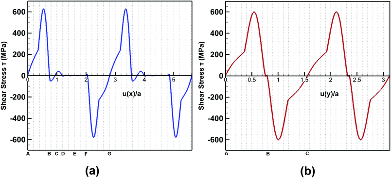 | ||
| Fig. 16 Stress strain behaviour of bilayer bonded germanene structure under shear loading along (a) armchair direction and (b) zigzag direction. | ||
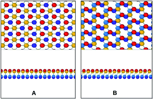
In Fig. 17, the initial position of the system is shown in A. The system is at A–B stacking in the initial stable position where the two layers are bonded together. When the system is displaced from this initial position, shear force acts in an opposite direction to prevent that movement. This opposing shear stress keeps increasing up to μ(x)/a = 0.55 where it reaches its maximum value of nearly 628 MPa. When the top layer is further displaced, the shear stress decreases and reaches zero at μ(x)/a = 0.75 at position B (the strains corresponding to the atomic configurations in Fig. 17 and 18 are marked in Fig. 16). From there the system approaches A–A stacking, acquires A–A stacking at position C (shown in Fig. 17) and holds its influence until position D. Due to the relative position of the two layers in this B–C–D range, the corresponding shear force is comparatively low. It is observed that in A–A stacking the distance between the atoms of the two layers is 3.14 Å, so no covalent bond can be formed in this stacking. Hence less force is required to displace the top sheet in this range. When the top layer is further translocated from D, the shear force remains zero through the D–E–F region because in position E shown in Fig. 17, the topmost atoms of the top layer are above the bottommost atoms of the lower layer, so the interaction between the two layers become very less as their distance (3.81 Å) exceeds the cutoff of the potential between the two layers. When further displacement from position F is applied, shear force favours the displacement until it reaches G completing one period.
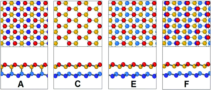 | ||
| Fig. 17 Configurations at different shift positions while interlayer sliding along armchair direction. | ||
After the system is displaced from initial position as shown in Fig. 18 with configuration A, shear force first opposes the movement increasingly up to μ(y)/a = 0.52 where it reaches maximum value of 600 MPa. Then with further displacement, shear force decreases and reaches zero at μ(y)/a = 0.8.
Then with further displacement, the shear force favours the movement and so the shear stress remains negative until one period is completed. It is observed that the shear strength is higher by ∼5% along the armchair direction when compared to the zigzag direction. Interlayer bonds are broken when the top layer tries to slide with respect to the bottom layer. It is observed that the number of bonds per unit area that break under armchair loading is higher than that of zigzag loading direction. So, when shear loading is applied on the top layer along the armchair direction, more bonds have to be broken, so more force is required to displace it. Hence, the shear strength is also higher in this direction.
4. Conclusions
Presented herein is the investigation of mechanical properties of bonded bilayer germanene structure using optimized Tersoff potential with MD simulations. It is found from the study that fracture strength of bilayer germanene is sensitive to chirality, temperature, defects and strain rate. Fracture strength along the armchair direction is found to be greater than that along the zigzag loading direction which is an interesting phenomenon for 2D honeycomb structures. Higher temperature reduces fracture strength and fracture strain and these reductions are more significant in case of armchair loading. It has been observed that temperature has more significant effect in case of the bilayer structure than the single layer structure. Moreover, it is found that higher strain rate results in higher fracture strength. However, this effect is less significant than that of temperature. Analysis of strain rate sensitivity shows that the structure is more sensitive to strain rate variation in higher temperatures. In this research, five different defected structures have been studied and the results reveal that in case of zigzag loading, presence of defects has less effect on mechanical properties. Further analysis shows that bi-vacancy on both layers causes maximum reduction in fracture strength in both loading directions, while mono-vacancy on a single layer causes the minimum change in this property. The interlayer shear characteristics have also been elucidated in this study. Shear strength along the armchair direction is found to be higher than that of the zigzag direction for the BBGS. In summary, this study reveals the effect of temperature, defects and strain rate on the mechanical properties of bilayer germanene sheets coupled by covalent bonding as well as interlayer shear characteristics and it is expected to serve as a guide for further analysis of germanene based structure in nanoelectronics applications.Conflicts of interest
There are no conflicts to declare.Acknowledgements
The authors of this paper would like to acknowledge the support from the Department of Mechanical Engineering, BUET for providing the computational facilities for this work.References
- H. Chen, M. B. Müller, K. J. Gilmore, G. G. Wallace and D. Li, Adv. Mater., 2008, 20, 3557–3561 CrossRef CAS.
- A. K. Geim and K. S. Novoselov, Nat. Mater., 2007, 6, 183–191 CrossRef CAS.
- C. Lee, X. Wei, J. W. Kysar and J. Hone, Science, 2008, 321, 385–388 CrossRef CAS.
- X. Zhao, Q. Zhang, D. Chen and P. Lu, Macromolecules, 2010, 43, 2357–2363 CrossRef CAS.
- C. Mattevi, G. Eda, S. Agnoli, S. Miller, K. A. Mkhoyan, O. Celik, D. Mastrogiovanni, G. Granozzi, E. Garfunkel and M. Chhowalla, Adv. Funct. Mater., 2009, 19, 2577–2583 CrossRef CAS.
- D. Wei, Y. Liu, Y. Wang, H. Zhang, L. Huang and G. Yu, Nano Lett., 2009, 9, 1752–1758 CrossRef CAS.
- A. H. Castro Neto, F. Guinea, N. M. R. Peres, K. S. Novoselov and A. K. Geim, Rev. Mod. Phys., 2009, 81, 109–162 CrossRef CAS.
- A. I. Khan, I. A. Navid, M. Noshin, H. M. A. Uddin, F. F. Hossain and S. Subrina, Electronics, 2015, 4, 1109–1124 CrossRef CAS.
- Z. Ding, J.-W. Jiang, Q.-X. Pei and Y.-W. Zhang, Nanotechnology, 2015, 26, 065703 CrossRef CAS PubMed.
- S. Cahangirov, M. Topsakal, E. Aktürk, H. Şahin and S. Ciraci, Phys. Rev. Lett., 2009, 102, 236804 CrossRef CAS.
- E. Bianco, S. Butler, S. Jiang, O. D. Restrepo, W. Windl and J. E. Goldberger, ACS Nano, 2013, 7, 4414–4421 CrossRef CAS.
- S. Jiang, S. Butler, E. Bianco, O. D. Restrepo, W. Windl and J. E. Goldberger, Nat. Commun., 2014, 5, 3389 CrossRef.
- L. Li, S. Lu, J. Pan, Z. Qin, Y. Wang, Y. Wang, G. Cao, S. Du and H.-J. Gao, Adv. Mater., 2014, 26, 4820–4824 CrossRef CAS.
- M. E. Dávila, L. Xian, S. Cahangirov, A. Rubio and G. L. Lay, New J. Phys., 2014, 16, 095002 CrossRef.
- M. Derivaz, D. Dentel, R. Stephan, M.-C. Hanf, A. Mehdaoui, P. Sonnet and C. Pirri, Nano Lett., 2015, 15, 2510–2516 CrossRef CAS.
- M. E. Dávila and G. Le Lay, Sci. Rep., 2016, 6, 20714 CrossRef.
- E. Scalise, M. Houssa, G. Pourtois, B. van den Broek, V. Afanas'ev and A. Stesmans, Nano Res., 2013, 6, 19–28 CrossRef CAS.
- S. Balendhran, S. Walia, H. Nili, S. Sriram and M. Bhaskaran, Small, 2015, 11, 640–652 CrossRef CAS.
- S. J. Mahdizadeh and G. Akhlamadi, J. Mol. Graphics Modell., 2017, 72, 1–5 CrossRef CAS.
- A. Nijamudheen, R. Bhattacharjee, S. Choudhury and A. Datta, J. Phys. Chem. C, 2015, 119, 3802–3809 CrossRef CAS.
- Z. Ni, Q. Liu, K. Tang, J. Zheng, J. Zhou, R. Qin, Z. Gao, D. Yu and J. Lu, Nano Lett., 2012, 12, 113–118 CrossRef CAS.
- L. Matthes, O. Pulci and F. Bechstedt, J. Phys.: Condens. Matter, 2013, 25, 395305 CrossRef PubMed.
- X. Chen, Q. Yang, R. Meng, J. Jiang, Q. Liang, C. Tan and X. Sun, J. Mater. Chem. C, 2016, 4, 5434–5441 RSC.
- C. Huang, J. Zhou, H. Wu, K. Deng, P. Jena and E. Kan, J. Phys. Chem. Lett., 2016, 7, 1919–1924 CrossRef CAS.
- C.-C. Liu, W. Feng and Y. Yao, Phys. Rev. Lett., 2011, 107, 076802 CrossRef.
- C.-C. Liu, H. Jiang and Y. Yao, Phys. Rev. B: Condens. Matter Mater. Phys., 2011, 84, 195430 CrossRef.
- G. Baskaran, in Many-body Approaches at Different Scales: A Tribute to Norman H. March on the Occasion of his 90th Birthday, ed. G. G. N. Angilella and C. Amovilli, Springer International Publishing, Cham, 2018, pp. 43–57 Search PubMed.
- B. Mortazavi, A. Dianat, G. Cuniberti and T. Rabczuk, Electrochim. Acta, 2016, 213, 865–870 CrossRef CAS.
- X. Wang and Z. Wu, Phys. Chem. Chem. Phys., 2017, 19, 2148–2152 RSC.
- D. K. Sharma, S. Kumar, A. Laref and S. Auluck, Computational Condensed Matter, 2018, 16, e00314 CrossRef.
- R. Paul, T. Tasnim, S. Saha and M. Motalab, Mater. Res. Express, 2018, 5, 015062 CrossRef.
- M.-Q. Le, Int. J. Mod. Phys. B, 2018, 32, 1850241 CrossRef CAS.
- K. Yang, S. Cahangirov, A. Cantarero, A. Rubio and R. D'Agosta, Phys. Rev. B: Condens. Matter Mater. Phys., 2014, 89, 125403 CrossRef.
- X. Chen, X. Sun, J. Jiang, Q. Liang, Q. Yang and R. Meng, J. Phys. Chem. C, 2016, 120, 20350–20356 CrossRef CAS.
- P. Liang, Y. Liu, S. Xing, H. Shu and B. Tai, Solid State Commun., 2016, 226, 19–24 CrossRef CAS.
- M. Ali, X. Pi, Y. Liu and D. Yang, AIP Adv., 2017, 7, 045308 CrossRef.
- J.-W. Jiang, J.-S. Wang and B. Li, Phys. Rev. B: Condens. Matter Mater. Phys., 2009, 80, 113405 CrossRef.
- R. Kumar, G. Rajasekaran and A. Parashar, Nanotechnology, 2016, 27, 085706 CrossRef.
- Q.-X. Pei, Z.-D. Sha, Y.-Y. Zhang and Y.-W. Zhang, J. Appl. Phys., 2014, 115, 023519 CrossRef.
- X. Wang, D. Han, Y. Hong, H. Sun, J. Zhang and J. Zhang, ACS Omega, 2019, 4, 10121–10128 CrossRef CAS.
- M. M. Monshi, S. M. Aghaei and I. Calizo, Surf. Sci., 2017, 665, 96–102 CrossRef CAS.
- S. Plimpton, J. Comput. Phys., 1995, 117, 1–19 CrossRef CAS.
- S. Plimpton, Comput. Mater. Sci., 1995, 4, 361–364 CrossRef CAS.
- T. Belytschko, S. P. Xiao, G. C. Schatz and R. S. Ruoff, Phys. Rev. B: Condens. Matter Mater. Phys., 2002, 65, 235430 CrossRef.
- M.-Q. Le and R. C. Batra, Comput. Mater. Sci., 2016, 118, 251–258 CrossRef CAS.
- N. Chandra, S. Namilae and C. Shet, Phys. Rev. B: Condens. Matter Mater. Phys., 2004, 69, 094101 CrossRef.
- M. R. Chávez-Castillo, M. A. Rodríguez-Meza and L. Meza-Montes, RSC Adv., 2018, 8, 10785–10793 RSC.
- S. Wang, Y. Chen, Y. Ma, Z. Wang and J. Zhang, J. Appl. Phys., 2017, 122, 074301 CrossRef.
- Y. D. Kuang, L. Lindsay, S. Q. Shi and G. P. Zheng, Nanoscale, 2016, 8, 3760–3767 RSC.
- R. E. Roman and S. W. Cranford, Comput. Mater. Sci., 2014, 82, 50–55 CrossRef CAS.
- Y. Huang, J. Wu and K. C. Hwang, Phys. Rev. B: Condens. Matter Mater. Phys., 2006, 74, 245413 CrossRef.
- S. Cranford and M. J. Buehler, Modell. Simul. Mater. Sci. Eng., 2011, 19, 054003 CrossRef.
- B. Mortazavi, O. Rahaman, M. Makaremi, A. Dianat, G. Cuniberti and T. Rabczuk, Phys. E, 2017, 87, 228–232 CrossRef CAS.
- H. Zhang and R. Wang, Phys. B, 2011, 406, 4080–4084 CrossRef CAS.
- T. P. Kaloni, J. Phys. Chem. C, 2014, 118, 25200–25208 CrossRef CAS.
- A. Mahata and T. Mukhopadhyay, Phys. Chem. Chem. Phys., 2018, 20, 22768–22782 RSC.
- Y. Y. Zhang, C. M. Wang, Y. Cheng and Y. Xiang, Carbon, 2011, 49, 4511–4517 CrossRef CAS.
- S. Mojumder, A. A. Amin and M. M. Islam, J. Appl. Phys., 2015, 118, 124305 CrossRef.
- J. E. Padilha and R. B. Pontes, Solid State Commun., 2016, 225, 38–43 CrossRef CAS.
- Y. Li, W. Zhang, B. Guo and D. Datta, Acta Mech. Solida Sin., 2017, 30, 234–240 CrossRef.
Footnote |
| † Electronic supplementary information (ESI) available. See DOI: 10.1039/c9ra06003k |
| This journal is © The Royal Society of Chemistry 2019 |

