
 Open Access Article
 This Open Access Article is licensed under a Creative Commons Attribution-Non Commercial 3.0 Unported Licence
Asymmetric faradaic assembly of Bi2O3 and MnO2 for a high-performance hybrid electrochemical energy storage device†
Saurabh
Singh
 a,
Rakesh K.
Sahoo
b,
Nanasaheb M.
Shinde
c,
Je Moon
Yun
b,
Rajaram S.
Mane
c,
Wonsub
Chung
*a and
Kwang Ho
Kim
*abc
a,
Rakesh K.
Sahoo
b,
Nanasaheb M.
Shinde
c,
Je Moon
Yun
b,
Rajaram S.
Mane
c,
Wonsub
Chung
*a and
Kwang Ho
Kim
*abc
aDepartment of Materials Science and Engineering, Pusan National University, Busan, Republic of Korea. E-mail: kwhokim@pusan.ac.kr; wschung1@pusan.ac.kr
bGlobal Frontier R&D Centre for Hybrid Interface Materials, Pusan National University, Busan, Republic of Korea
cNational Core Research Centre for Hybrid Materials Solution, Pusan National University, Busan, Republic of Korea
First published on 9th October 2019
Abstract
In the current study, we have explored the coupling of Bi2O3 negative electrode and MnO2 positive electrode materials as an asymmetric faradaic assembly for a high-performance hybrid electrochemical energy storage device (HEESD). Aiming at a low-cost device, both the electrodes have been synthesized by a simple, scalable, and cost-effective chemical synthesis method. After their requisite structure-morphological confirmation and correlation, these electrodes were separately examined for their electrochemical performance in a three-electrode configuration. The results obtained confirm that Bi2O3 and MnO2 exhibit 910 C g−1 and 424 C g−1 specific capacity, respectively, at 2 A g−1 current density. Notably, the performance of both electrodes has been analyzed using Dunn's method to highlight the distinct nature of their faradaic properties. Afterwards, the asymmetric faradaic assembly of both electrodes, when assembled as a HEESD (MnO2//Bi2O3), delivered 411 C g−1 specific capacity at 1 A g−1 current density due to the inclusive contribution from the capacitive as well as the non-capacitive faradaic quotient. Consequently, the assembly offers an excellent energy density of 79 W h kg−1 at a power density of 702 W kg−1, with a magnificent retention of energy density up to 21.1 W h kg−1 at 14![[thin space (1/6-em)]](https://www.rsc.org/images/entities/char_2009.gif) 339 W kg−1 power density. Moreover, it demonstrates long-term cycling stability at 10 A g−1, retaining 85.2% of its initial energy density after 5000 cycles, which is significant in comparison with the previously reported literature. Additionally, to check the performance of the device in real time, two HEESDs were connected in series to power a light-emitting diode. The results obtained provide significant insight into hybrid coupling, where two different faradaic electrodes can be combined in a synergistic combination for a high-performance HEESD.
339 W kg−1 power density. Moreover, it demonstrates long-term cycling stability at 10 A g−1, retaining 85.2% of its initial energy density after 5000 cycles, which is significant in comparison with the previously reported literature. Additionally, to check the performance of the device in real time, two HEESDs were connected in series to power a light-emitting diode. The results obtained provide significant insight into hybrid coupling, where two different faradaic electrodes can be combined in a synergistic combination for a high-performance HEESD.
1. Introduction
In the twenty-first century, electrochemical energy storage devices are one of the most crucial components of modern technological systems, and, therefore, the subject of a lot of research attention among scientific and technical communities.1–3 In particular, demand for portable forms is high in order to launch successful electric vehicles and electronic gadgets with improved efficiency. Currently, batteries and supercapacitors are two emerging and popular electrochemical energy storage devices that are widely available in the market, but they also possess some drawbacks that are contrary to each other.4–7 For achieving high energy density, both devices rely on faradaic redox reactions. However, due to the distinct characteristics of the faradaic reactions in these devices they have pros and cons.8,9 In the case of batteries, the faradaic reactions are predominantly diffusion controlled and occur in the bulk of the material, which leads to them being a favorable energy delivery device but with compromised power density. At the other extreme, in the case of supercapacitors, the faradaic reactions are highly surface driven, which leads to them being favorable power delivery devices but with compromised energy density. To address these drawbacks it is highly desirable to construct an energy storage device that favors high energy density along with high power density in a single device.9 Indeed, realizing such a device is possible if the faradaic sources used in batteries and supercapacitors are rationally integrated to exhibit properties of both batteries and supercapacitors simultaneously.10–15An intuitive way to incorporate these faradaic sources in a single device can be coupling the sources as negatrode, i.e., a negative electrode, and as positrode, i.e., positive electrode, material to form an asymmetric faradaic assembly.4,16 Since the two sources are distinct, as previously discussed, the asymmetric faradaic assembly will give rise to a hybrid electrochemical energy storage device (HEESD). Here, the term faradaic assembly has been coined to make the distinction with devices where coupling has been explored between faradaic and non-faradaic electrodes (the EDLC type device).10,17,18 In fact, this intentional distinction allows comparison of the outcomes for both types of coupling, highlighting the benefits of one over the other. However, in order to fulfil the objective of faradaic coupling, it is important that there should be perfect synergy between both the electrodes, so that successful coupling of their energy density and power density performance can be achieved. Therefore, wise selection of faradaic materials as negatrode and positrode is required, where they are not only an excellent source of high energy density and high power density, but they can also offer optimal synergy between them to obtain a high-performance HEESD.
Among different types of electrochemical energy storage materials, Bi2O3 and MnO2 are two unique faradaic-type materials. Primarily, Bi2O3 is known as a battery material,19,20 having high dielectric permittivity, biocompatibility, nontoxicity, a theoretical capacity about 2484 C g−1 and a large band gap of 2.8 eV.21–23 Moreover, its layered structure parallel to the (100) plane in the c-axis direction signifies its suitability for high charge storage.23 Previously, Bi2O3 has been demonstrated as a promising negatrode material for electrochemical energy storage applications.24–26 Recently, our group also reported marigold- and nanoflower-like Bi2O3 nanostructures as a negatrode material.27,28 Similarly, MnO2 is known for its capacitive characteristics, attracting enormous research interest owing to its high abundance, environmentally friendly properties, and low cost.29,30 Due to its high theoretical specific capacitance of 1370 F g−1, it is regarded as a promising electrode material for supercapacitor applications.26 Previously, in most work on MnO2 it has been used as a positrode material with a wide potential window, delivering impressive supercapacitive performances.31–33 The amazing properties pertaining to Bi2O3 and MnO2 persuaded Huang et al. to fabricate a flexible supercapacitor device out of these two materials, which exhibited energy density up to 11.3 W h kg−1 at a power density of 3370 W kg−1.34 Furthermore, Lim et al. also reported a symmetric supercapacitor device consisting of a Bi2O3 and MnO2 composite as the supercapacitor electrode, which produced an energy density of 9.5 W h kg−1 at a power density of 3370 W kg−1.35 These reported results suggest that Bi2O3 and MnO2 are not only excellent choices as electrode material, but also lead to an impressive as well as relatively cheap assembly for energy storage device application. However, this is not the best energy storage performance obtained so far from the Bi2O3 and MnO2 assembly, therefore, significant improvements are needed for the assembly, but in an economical way and avoiding any environmental hazards during the development. Hence, our work is focused on developing a high-performance Bi2O3 negatrode and MnO2 positrode using a low cost, scalable and eco-friendly method, and then coupling these electrodes as an asymmetric faradaic assembly in order to obtain a high-performance HEESD. Additionally, an attempt has been made to clearly highlight the hybrid characteristics of the HEESD by segregating device performance in terms of capacitive as well as non-capacitive contributions. Furthermore, to demonstrate the potential applicability of the HEESD, a light-emitting diode has been powered by connecting two HEESDs in series.
2. Experimental details
2.1 Materials
All the reagents used in the present work were of analytical grade and used as received. Bismuth chloride (BiCl3 > 98%), sodium hydroxide (NaOH > 98%), potassium permanganate (KMnO4 > 97%), and potassium hydroxide (KOH > 85%) were purchased from Sigma-Aldrich. Deionized (DI) water obtained from Millipore was used throughout the experiment.2.2 Synthesis of Bi2O3 nanostructure as a negatrode
The Bi2O3 nanostructure was synthesized by using a simple solid-state reaction method via mixing of two readily available and low-cost reactants, i.e. BiCl3 and NaOH. In a typical solid-state synthesis of the Bi2O3 nanostructure, 4 g of the powder metal precursor and 2 g of NaOH (2:1 w/w) were ground together using an agate mortar for 15–20 min. A thick slurry, in the form of a paste, was obtained after completion of the reaction. The slurry was washed by dispersing it into the water and then centrifuged to separate the product. This process was repeated at least three to four times to minimize the amount of reactant in the final product. After washing, the product was dried at 60 °C in an oven. Finally, the dried product was annealed at 300 °C for 1 h in a horizontal tube furnace.
Fabrication of the Bi2O3 negatrode was done by mixing active material (the final product obtained after annealing) with acetylene black and polytetrafluoroethylene (PTFE) suspension (60 wt%) as a binder at a weight ratio of 8:1:1, and then loading onto a nickel foam, which served as a current collector. The mass loading of the active material was kept at approximately 3.5 mg cm−2. Finally, the negatrode was dried in a vacuum oven at 60 °C for 12 h.
2.3 Synthesis of MnO2 nanostructure as a positrode
The positrode was prepared by growing the MnO2 nanostructure directly onto the Ni foam via a facile hydrothermal method without any surfactant. In a typical procedure, KMnO4 (1.85 mmol) was dissolved in water (30 mL) with agitation at room temperature. After stirring for 10 min in air, the solution was transferred to a Teflon-lined stainless-steel autoclave containing a piece of Ni foam (dimensions 5 × 4 cm2). Then, the autoclave was placed in an electric oven and heated to 150 °C for 1.5 h and then cooled naturally to room temperature. Finally, the Ni foam was washed by water and absolute ethanol repeatedly to remove any possible residual impurities, and then dried in an oven at 80 °C overnight.2.4 Material characterization
Crystallographic characterization of Bi2O3 negatrode and MnO2 positrode material was obtained using a D8-Discovery Bruker diffractometer with Cu Kα (λ = 1.5405 Å) at a voltage of 40 kV and a current of 40 mA. The microstructure and surface morphology of both the samples were examined by field-emission scanning electron microscopy (FESEM, Hitachi, S-4800, 15 kV). Transmission electron microscopy (TEM), high-resolution TEM (HRTEM) and high-angle annular dark-field scanning transmission electron microscopy (HAADF-STEM) images were also obtained, using an FEI Tecnai F20, equipped with an energy dispersive X-ray spectrometer (EDX). Elemental mapping was done using EDX, operated with a probe focused to 0.2 nm and a camera length of 20 cm. Measurement of surface area and pore size distribution was performed using a Micromeritics ASAP 2010 analyzer. A Barrett–Joyner–Halenda (BJH) plot and Brunauer–Emmett–Teller (BET) isotherm were used to confirm the type of porosity and the surface area of the material. X-ray photoelectron spectroscopy (XPS) analysis of both the samples was conducted on a VG Scientifics ESCALAB250 calibrated to a carbon peak (C 1s) located at 284.6 eV.2.5 Electrochemical measurements
Initially, separate electrochemical measurements of the MnO2 positrode and Bi2O3 negatrode were carried out on a three-electrode set-up, where both the electrodes were used as a working electrode. A piece of platinum foil (facing towards the working electrode) and Hg/HgO were used as the counter and the reference electrode, respectively. The distance between the working electrode and the counter electrode was fixed to ∼1 cm. During the measurement, both the electrodes were separately subjected to cyclic voltammetry (CV), galvanostatic charge/discharge (GCD), and electrochemical impedance spectroscopy (EIS) measurements. All the analyses were performed on an Ivium-n-Stat electrochemical workstation (Ivium, The Netherlands). EIS spectra were obtained in the frequency range of 100 kHz to 0.01 Hz with AC voltage amplitude of 5 mV. Later, the HEESD was measured on the same station using two terminals. Aqueous KOH electrolyte of molarity 3 M was used throughout the measurements. The specific capacity calculation for the electrodes and HEESD, as well as the energy density and power density calculations for the HEESD, are described in the ESI (S0†) according to previously reported methods.363. Results and discussion
3.1 Crystallographic analysis
X-ray diffraction (XRD) characterization was obtained to confirm the structure and phase of Bi2O3 and MnO2. The XRD pattern for Bi2O3 is shown in Fig. 1a, and demonstrates well-defined diffraction peaks for the Bi2O3 nanostructure, scanned within the 2θ range 19–51°. All the peaks appearing in the XRD pattern agree well with JCPDS no. 041-1449. The diffraction pattern corresponds to α-Bi2O3, which is indexed as a monoclinic lattice with the linear parameters a = 5.8499, b = 8.1698, c = 7.5123 Å and P21/c space group. The most prominent peak appearing at 27.37° is a reflection of the (120) plane having an interplanar spacing (d) 3.25 Å. As per the literature, this d value is sufficient for ion intercalation–deintercalation during the charge/discharge process.37 Additionally, the peak intensity and sharpness of this peak indicate the superior crystallinity of the sample.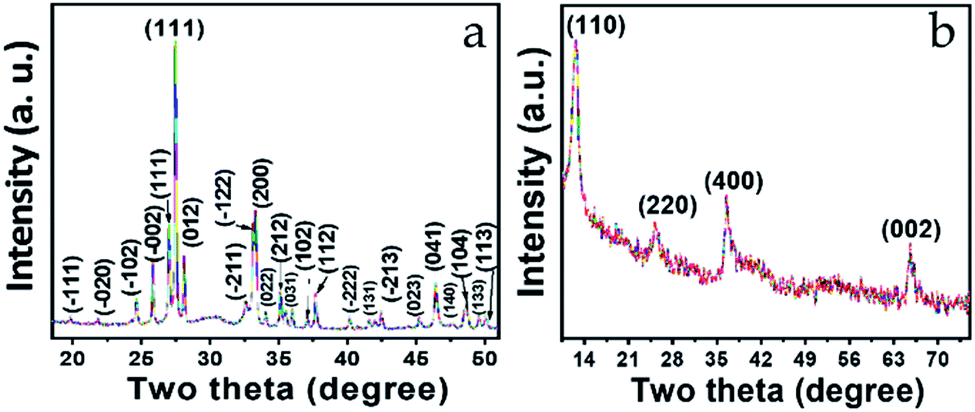 | ||
| Fig. 1 XRD pattern of (a) Bi2O3 and (b) MnO2 nanostructure. | ||
Similarly, Fig. 1b shows the typical XRD pattern of the MnO2 nanostructure. Four well-defined diffraction peaks appearing at 12.7°, 25.6°, 36.5°, and 65.5° were successfully indexed to the (100), (220), (400), and (002) planes, respectively. These planes are the reflection of the tetragonal lattice system and agree well with JCPDS-01-0721982. Meanwhile, the interplanar spacings (d value) corresponding to the indexed planes are 6.94 Å, 3.47 Å, 2.45 Å, and 1.42 Å, respectively, where the noticeable broadening in all four peaks is related to short-range lattice ordering of the nanostructure. Here, as well, the d values are quite favorable for the intercalation–deintercalation process. Moreover, no impurity peaks can be seen in either of the diffraction patterns (Fig. 1a and b), which confirms the phase purity of the materials.
3.2 Compositional analysis
XPS was performed to investigate the different elemental composition and the existing chemical states for both the Bi2O3 and MnO2 nanostructures. The full XPS spectra clearly confirm the presence of the respective elements in the samples, with no other impurities (ESI Fig. S1†).The high-resolution XPS spectra are shown in Fig. 2a, b and c, d for the Bi2O3 and MnO2 nanostructures, respectively. As can be seen from Fig. 2a, the Bi 4f spectra clearly consist of two deconvoluted peaks at binding energy values of 163.7 and 158.4 eV, with a spin–orbit separation of 5.3 eV. In agreement with the literature, no significant shift can be seen in the binding energy value of the peaks, indicating the presence of bismuth in the +3 state.38 Meanwhile, two other less prominent peaks at higher binding energy among the four deconvoluted peaks can be attributed to a slight surface charging effect from the polarization change in the crystal.39,40 Moreover, the presence of oxygen species in the Bi2O3 composition is corroborated by the deconvoluted peaks of the O 1s signal shown in Fig. 2b, which appear and are centered at binding energy values of 529.1, 530.6, and 531.7 eV. These values can be attributed to the surface-adsorbed oxygen species, lattice oxygen of bismuth oxide and the impurity-related oxygen species, respectively.41 Furthermore, Fig. 2c shows the high-resolution 2p spectrum of Mn, where its characteristic spin–orbit peaks for Mn 2p1/2 and Mn 2p3/2 are located at a binding energy of 652.3 and 640.5 eV, respectively. With no significant fluctuation in the peak values and the peaks exhibiting a spin–energy separation of 11.8 eV this confirms the presence of Mn in the +4 valence state, in good agreement with the previously reported literature.32 The oxide formation is confirmed by the O 1s signal shown in Fig. 2d, which is deconvoluted into three components at 530.2, 531.5 and 532.6 eV, corresponding to the lattice oxygen, the hydroxyl component and the structurally adsorbed water, respectively. Thus, the elemental valence states are pertinent to the formation of the Bi2O3 and MnO2 phases and verify the XRD observations.
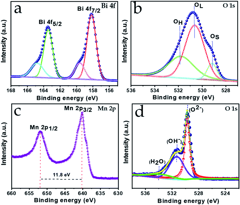 | ||
| Fig. 2 High-resolution XPS spectra of (a) Bi 4f, (b) O 1s and (c) Mn 2p, (d) O 1s for Bi2O3 and MnO2, respectively. | ||
3.3 Morphological analysis of Bi2O3 and MnO2 nanostructures
SEM was used to observe the surface morphology of the as-synthesized Bi2O3 and MnO2 nanostructures. Fig. 3a and b shows the surface morphology of the Bi2O3 nanostructure at low and high magnification. From these images, well-defined sandstone-like nanoparticles can be clearly seen. These nanoparticles exist in a variety of shapes and sizes with partial aggregation, however, their distribution can be easily identified. The average thickness of the nanoparticles, as measured from the high magnification micrograph (Fig. 3b), lies between approximately 60 and 80 nm, while diverse disc-shape sizes are observed with hundreds of nanometers. These unique, but partly agglomerated, nanoparticles are able to achieve a good surface area as measured for the as-synthesized powder of the Bi2O3 nanostructure. BET measurement shows that the as-synthesized Bi2O3 nanostructure has a 22.5 m2 g−1 surface area, along with a BJH total pore volume and mean pore diameter of approximately 0.18 cm3 g−1 and 72.17 Å, respectively (ESI Fig. S2†). Structural details for the Bi2O3 were further studied using TEM and HRTEM characterization (Fig. 3c–e). As shown in Fig. 3c, the TEM micrograph again confirms the morphology of the Bi2O3 nanoparticles, since they appear exactly as observed in the SEM micrograph. Furthermore, the HRTEM image in Fig. 3d confirms formation of the Bi2O3 α-phase, as the lattice spacing of 3.25 Å matches with the interplanar spacing of the XRD (120) plane. In addition, the bright spots in the SAED pattern in Fig. 3e indicate the single crystalline phase. Moreover, Fig. 3f shows the HAADF-STEM image of the same material, with Fig. 3g and h showing the corresponding EDX mapping, and confirms the presence, as well as the uniform distribution of bismuth and oxygen, in a single disc-shape nanoparticle ranging from 100 to 700 nm in dimension.In Fig. 4a and b, the SEM micrographs of the MnO2 nanostructure at low (1 μm, scale bar) and high magnification (200 nm, scale bar) clearly show uniform distribution of a nanoflower array comprising many wrinkled nanosheets. The marked area in Fig. 4b shows that the thickness of the nanosheets is in the range 5 ± 2 nm. Meanwhile, a highly microporous nanostructure also features in the morphology, which is overwhelmingly beneficial for ion migration during electrochemical energy storage. Furthermore, the TEM micrograph (Fig. 4c) corroborates the SEM observation depicting a flowery and porous nanostructure, with the HRTEM image showing (inset in Fig. 4c) the thickness of the nanopetals in the range 5–7 nm. Again, the magnified HRTEM image shown in Fig. 4d confirms the crystalline characteristics of the nanopetals, with an interplanar lattice spacing of 2.45 Å, matching the d spacing of the MnO2 (400) crystal plane. The crystalline nature of the nanopetals is again confirmed by the ring-like SAED pattern, obtained from the marked area of Fig. 4c. EDX mapping was employed to analyze the elemental composition of the as-grown MnO2 nanosheets. Fig. 4f shows the HAADF image of the MnO2 nanosheets, with the corresponding elemental mapping shown in Fig. 4g and h confirming the homogeneous distribution of manganese and oxygen throughout the nanosheet.
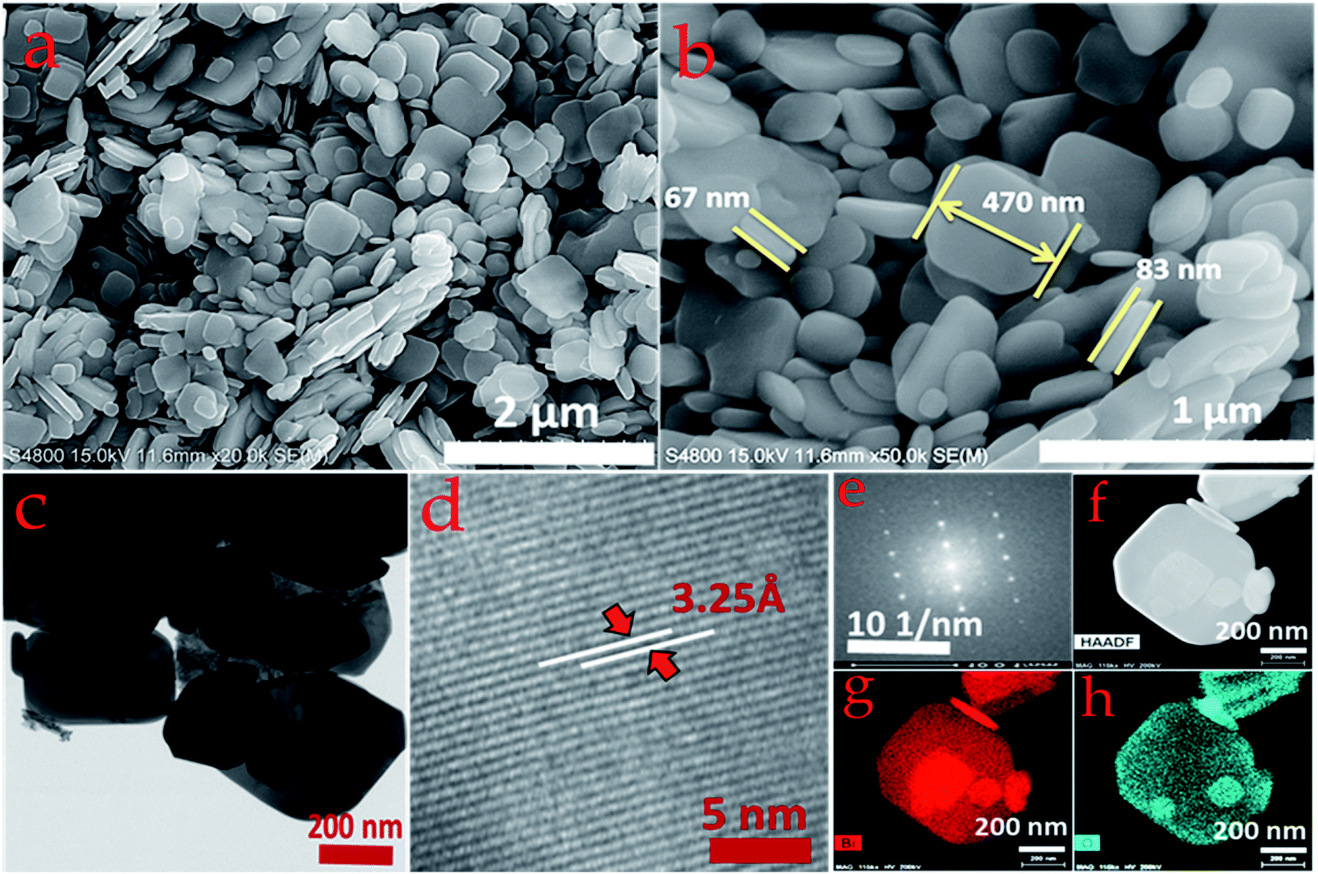 | ||
| Fig. 3 (a) Low magnification and (b) high magnification FESEM images of the Bi2O3 nanostructure and the corresponding (c) TEM and (d) HRTEM images. (e) SAED pattern. (f) HAADF image. (g and h) EDX mapping of Bi and O elements. | ||
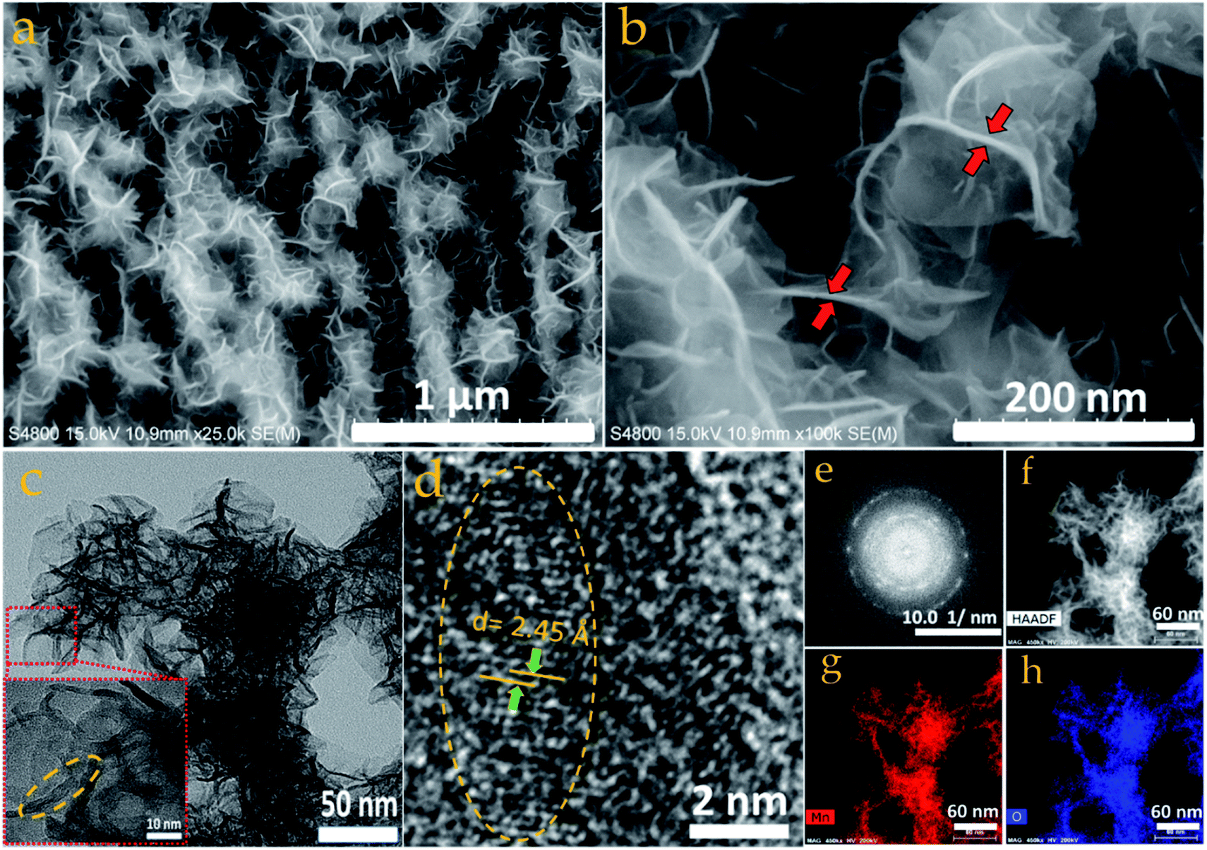 | ||
| Fig. 4 (a) Low magnification and (b) high magnification FESEM image of MnO2 nanostructure featuring nanoflower-like morphology, and the corresponding (c) TEM (inset: HRTEM featuring porous structure and multilayer nano petals) and (d) HRTEM image with lattice fringes. (e) SAED pattern from the imaging area shown in (c). (f) HAADF image. (g and h) EDS mapping showing the presence of Mn and O elements. | ||
4. Electrochemical study
4.1 Electrochemical performance of Bi2O3 as a negatrode
Electrochemical measurements of the Bi2O3 negatrode were conducted in a three-electrode configuration containing 3 M KOH electrolyte (Fig. 5). CV curves scanned at scan rates from low (5 mV s−1) to high (50 mV s−1) within the potential window of −1.0 to 0 V are shown in Fig. 5a. It can be seen that the response of the oxidation and reduction peak current signals in the CV curves consistently increase towards higher scan rates. Such high current signals suggest a large amount of electron transfer due to effective utilization of electroactive Bi species, conferring better charge storage capacity to the negatrode, even at high scan rate. The large redox peaks appearing in the CV curves can be ascribed to rapid quasi-reversible faradaic reactions between Bi3+ and Bi0 oxidation states.42 The possible quasi-reversible faradaic responses owing to the intercalation/deintercalation of electrolyte ions can be expressed as follows;| Bi2O3 + 3H2O + 6e− ↔ 2Bi + 6OH− | (1) |
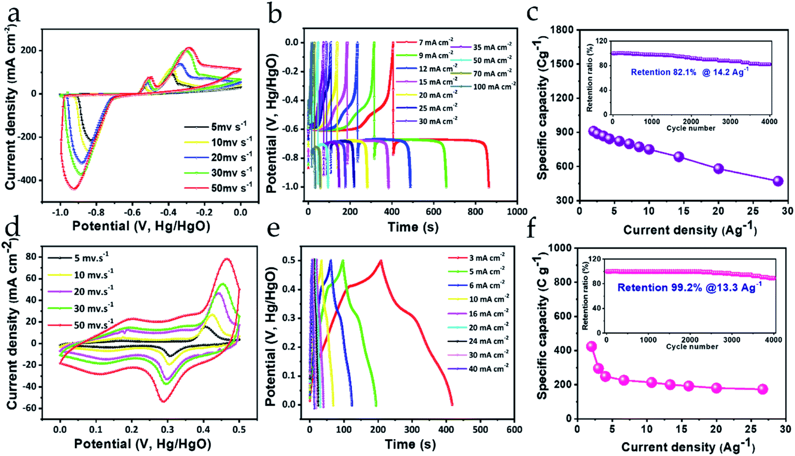 | ||
| Fig. 5 (a and d) CV, (b and e) GCD, and (c and f) rate capability (with the insets) of the Bi2O3 negatrode and MnO2 positrode in the first row and second row, respectively. | ||
Noticeably the separation between the redox peaks is quite high, and continues to separate further with increasing scan rate, indicating that the faradaic characteristic of the negatrode is primarily of the non-capacitive type. Detailed analysis of the non-capacitive faradaic contribution is discussed further in the next section. However, this suggests that the charge storage property emerges mainly from the bulk of the material. Importantly, the EIS response also indicates non-capacitive-type faradaic behavior for the Bi2O3 negatrode, signified by the large curvature of the Nyquist plot in the low-frequency region (ESI Fig. S3†). Furthermore, with increasing scan rate there are no significant changes in the shape of the CV curves, suggesting that Bi2O3 is a robust and chemically stable negatrode material.43,44 To determine the charge storing capability offered by the Bi2O3 negatrode, galvanic charge–discharge (GCD) measurements were performed (shown in Fig. 5b). We can observe that the GCD curves obtained exhibit a non-symmetric pattern, as well as a steep potential drop followed by a prolonged potential plateau, which clearly indicates the non-capacitive faradaic response.26,27 This implies that the Bi2O3 negatrode possesses a battery-type energy storage property.
To obtain the acquired specific capacities at different current density, GCD measurements were normalized with 3.5 g cm−2 of active material loaded onto a Ni foam. Therefore, the maximum specific capacity obtained at 2 A g−1 current density was calculated to be 910 C g−1, while at 28.57 A g−1 it is 479 C g−1 using eqn (1) (ESI S1†). The specific capacity obtained at low and high current density infers that the Bi2O3 negatrode can retain (at 28.57 A g−1) almost 52.6% of its initial specific capacity (at 2 A g−1), representing an impressive rate capability (shown in Fig. 5c). Furthermore, cycling stability is an essential parameter to judge the practical applicability of any electrode used in energy storage applications. As can be seen from Fig. 5c (inset), the stability was measured for over 4000 charge–discharge cycles at 14.2 A g−1, where 82.1% of the initial specific capacity was retained, which was verified by the GCD curves before and after cycling (ESI Fig. S4a†). This excellent cycling stability performance ensures good mechanical as well as chemical stability of the negatrode. Thus, the rate capability obtained and the cycling stability performance, including the high specific capacity of the Bi2O3 negatrode, can be attributed to the following features: (1) finely distributed nanocrystals facilitating a minimal diffusion pathway for the migration of ions; (2) a surface area that is widely exposed to the electrolyte; (3) good conductivity leading to faster transport kinetics for ions and electrons at the electrode/electrolyte interface; and (4) moderately high surface area for the nanostructure, possessing rich active sites. Importantly, the contribution of conductivity to the excellent electrochemical performance of the Bi2O3 negatrode is evident in the EIS performance, with its low series resistance as shown in the Nyquist plot (Fig. S3†).24
4.2 Electrochemical performance of MnO2 as a positrode
Fig. 5d–f shows the electrochemical measurement of the MnO2 positrode conducted in a three-electrode configuration containing 3 M KOH electrolyte. Fig. 5d shows the CV curves scanned from 5 mV s−1 to 50 mV s−1, in a potential range from 0 to +0.5 V. It is evident from the CV curves that the current density response of the peak increases consistently with increasing scan rate, implying effective utilization of electroactive Mn species, and, therefore, the positrode is capable of exhibiting substantial charge storage even at high current density. Furthermore, a pair of distinct redox peaks can be clearly observed at 0.48 V and 0.29 V, which are the oxidation and reduction peaks, respectively, arising from the rapid reversible faradaic reaction between Mn4+ and Mn3+ oxidation states. The reversible faradaic reaction emerges as a consequence of K+ ions from the electrolyte interacting with the MnO2 surface-active sites, which can be expressed using the following equation.32| MnO2 + xK+ + xe− ↔ KxMnO2 | (2) |
Again, it is worth noticing that all the CV curves enclose a definite area under their loop, which increases with increasing scan rate, along with the more protruding response of the redox peaks, suggesting fast charge transfer kinetics at the electrode–electrolyte interface, which could manifest into a high rate capability performance. Meanwhile, the areal pattern and the separation between the peaks signifies that the positrode is endowed with substantial charge storage property emerging from the capacitive (i.e., pseudocapacitive and EDLC type) as well as the non-capacitive faradaic activity. Similar inferences can be drawn from the GCD measurement of the MnO2 positrode. Fig. 5e shows the GCD profiles recorded at various areal current densities, from 3 mA cm−2 to 40 mA cm−2. Interestingly, the charge–discharge curves in the GCD profile exhibit nearly linear and partially asymmetric behavior, indicating that charge storage property of the positrode is primarily bestowed by a mixed type of faradaic activities (i.e., capacitive and non-capacitive). To obtain the gravimetric specific capacities from the GCD profiles, the respective areal current densities were normalized with the weight (1.5 mg cm−2) of active material grown on the Ni foam. The calculated maximum specific capacity 424 C g−1 is obtained at 2 A g−1 current density, which was retained up to 176 C g−1 at 26.6 A g−1 high current density. Fig. 5f represents the rate capability curve of the positrode, which shows that 41.5% of the specific capacity can still be maintained even at a high current density value of 26.6 A g−1, suggesting a substantial rate capability for the positrode. Such a rate capability performance can be obtained due to the good conductivity of the positrode, which is attributed to the low series resistance of the electrode, as observed from the EIS performance shown in the Nyquist plot (ESI Fig. S3†). Furthermore, the cycling stability was measured by repetitive charging and discharging of the MnO2 positrode at 13.3 A g−1 current density. As shown in Fig. 5f (inset), the positrode can retain about 89.2% of its initial specific capacity after 4000 charge–discharge cycles as is evident from the GCD curves before and after cycling (ESI Fig. S4b†), which is comparable to some of the previously reported literature.33,45,46 Hence, the cycling measurements confirm that the as-synthesized MnO2 nanostructure is mechanically robust and chemically stable as a positrode, and can withstand multiple charge–discharge cycles without any decline in its specific capacity.32 This excellent cyclic stability performance results from the uniformly distributed flower-like crystalline morphology, where the open porous nanostructure facilitates ion mobility toward interaction with the inner structure.
4.3 Electrochemical properties of the MnO2//Bi2O3 HEESD
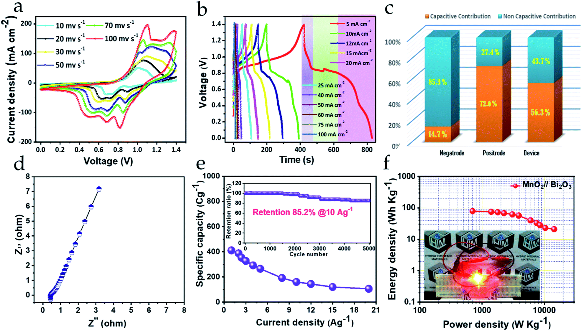
To construct the HEESD, the MnO2 positrode and Bi2O3 negatrode were stacked together and separated by a piece of filter paper soaked in 3 M KOH liquid electrolyte, as illustrated in Scheme 1. In order to balance the charge on both the electrodes, loading of active material weight was adjusted on the negatrode, therefore the mass ratio of Bi2O3 to MnO2 was controlled at approximately 0.46 during device fabrication. The electrochemical performance of the assembled device was studied by CV, GCD and EIS measurements using two-electrode set-ups, and the total weight of the material present on both the electrodes was used for evaluating the energy storage performance. The CV measurements were carried out at different scan rates within the range of 10–100 mV s−1 and are shown in Fig. 6a. Interestingly, we can follow that the different potential window marked for the negatrode CV curves (−1.0 to 0 V) and the positrode CV curves (0–0.5 V) when tested on the three-electrode set-up previously, now, in combination, give rise to a stable potential window of 1.4 V for the device assembly. Again, multiple redox peaks are clearly seen in the CV curves (Fig. 6a) due to active participation of redox-active sites from both the electrodes, indicating that the charge storing characteristics of the device are mainly of the faradaic type. Moreover, with increasing scan rate (up to 100 mV s−1), the same CV curves exhibit an increase in current density response, along with the area enclosed by the CV loops. This signifies the high rate capability performance, as well as the sound charge storage capability of the device. The above observations were substantiated in the GCD performance (shown in Fig. 6b), measured at different areal current densities (5–100 mA cm−2). We can see that all the GCD curves exhibit non-linear and asymmetric charge–discharge patterns, signaling a synergetic faradaic contribution from the positrode and the negatrode. A more explicit signature for the faradaic contribution of the positrode and negatrode is also evident from the discharge profile of the GCD curves, which are highlighted in three different regions (three different colors in Fig. 6b). Clearly, the first region (highlighted in a light violet color) and the third region (highlighted in a light purple color) exhibit a near-linear pattern, which is more likely to originate from the positrode, while the second region (highlighted in a light green color) exhibits a constant potential plateau, which is more likely to originate from the negatrode. In order to obtain a better assessment of the participation of the positrode and the negatrode in the charge storing capabilities of the device, a detailed investigation providing quantitative separation of the capacitive and non-capacitive charge storage has been done using Dunn's method for both the electrodes and the device.47–49 The detailed plots for the quantitative analysis are provided in the ESI Fig. S5–S7,† respectively. In Fig. 6c a bar diagram representation shows that 14.7%, 72.6% and 56.3% of the total charge storage is accounted for by the capacitive contribution, while 85.3%, 27.4%, and 56.3% is accounted for by the non-capacitive contribution, in the negatrode, positrode, and device, respectively. From the above results, we can conclude that the faradaic properties observed for the negatrode are mainly of a non-capacitive type and therefore it behaves as an energy bearing electrode, while for the positrode the properties are mainly of a capacitive type and it, therefore, behaves as a power bearing electrode. Meanwhile, assembly of both electrodes as a HEESD exhibits significant contributions from both the capacitive and non-capacitive faradaic activity, although the capacitive faradaic quotient is slightly higher than the non-capacitive one. This indicates that the device performance is significantly dependent on both the electrodes and could therefore yield excellent charge storage performance, as seen from the GCD curves in Fig. 6b. The specific capacities calculated based on the total weight deposited on the Ni foam, for both the negatrode and positrode, reach 411 C g−1, 353 C g−1, 327 C g−1, 292 C g−1, 264 C g−1, 192 C g−1, 160 C g−1, 144 C g−1, 120 C g−1, and 106 C g−1 at current densities of 1 A g−1, 2 A g−1, 3 A g−1, 4 A g−1, 5 A g−1, 8 A g−1, 10 A g−1, 12 A g−1, 15 A g−1, and 20 A g−1, respectively, which is substantially higher than many representative hybrid energy storage devices reported previously (Table 1).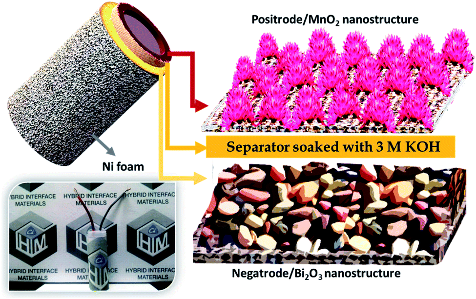 | ||
| Scheme 1 Pictorial views representing the morphologies for the electrodes (right), the schematic design of the HEESD (top left), and the original image (bottom left). | ||
 | ||
| Fig. 6 (a) CV, (b) GCD and (c) bar diagram highlighting the capacitive and non-capacitive contributions. (d) Nyquist plot. (e) Rate capability and cycling stability (inset) plot. (f) Ragone plot and LED demonstration for MnO2//Bi2O3 HEESD. | ||
| Active materials | Electrolyte | Capacitance | Energy density at specified power density | Cycling stability | Ref. |
|---|---|---|---|---|---|
| V2O5/CNT//V2O5/CNT | Gel electrolyte | 160 F g−1 at 1 A g−1 | 72 W h kg−1 at 2.3 kW kg−1 | 96% after 4000 cycles | 48 |
| MnO2//Fe3O4 | 0.1 M K2SO4 | 20 F g−1 | 7 W h kg−1 at 820 W kg−1 | Cycled for 5000 cycles | 50 |
| MnO2//Fe2O3 | Gel electrolyte | 91.3 F g−1 at 2 mA cm−2 | 0.32 mW h cm−3 at 139.1 mW cm−3 | 84% after 500 cycles at 2 mA cm−2 | 51 |
| GrMnO2//GrMoO3 | 1 M Na2SO4 | 307 F g−1 at 0.2 A g−1 | 42.6 W h kg−1 at 276 W kg−1 | Little deterioration after 1000 cycles at 50 mV s−1 | 52 |
| MnO2//FeOOH | 1 M Li2SO4 | 51 F g−1 at 0.5 A g−1 | 12 W h kg−1 at 3700 W kg−1 | 85% over 2000 cycles | 53 |
| Bi2O3/MnO2//Bi2O3/MnO2 | 1 M Na2SO4 | 79.4 F g−1 at 1 A g−1 | 9.5 W h kg−1 at 102 W kg−1 | ∼95% capacitance retained at 30 °C, upon 1000 cycles | 35 |
| VOx//VN | 5 M LiCl | 60.1 F g−1 at 0.5 mA cm−2 | 2.1 W h kg−1 | 87.5% for 10000 cycles |
54 |
| MnO2-60//V2O5NF | 1 M Na2SO4 | 70.2 at 1 mA cm−2 | 8.25 mW h cm−3 at 0.28 W cm−3 | 90.7% after 8000 cycles at 40 mA cm−2 | 31 |
| CNF at Bi2O3//MnO2 at CNF | 1 M Na2SO4 | 25.2 F g−1 at 1.5 mA cm−2 | 11.3 W h kg−1 at 352 W kg−1 | ≈85% even after 4000 cycles | 34 |
| Bi2O3//MnO2 | 3 M KOH | 411 C g −1 at 1A g −1 | 79 W h kg −1 at 702 W kg −1 | ∼at 10 A g−1 with 85.2% retention after 5000 cycles at room temperature | This work |
Furthermore, EIS measurements were performed to understand the promising electrochemical performance of the device. The Nyquist plot obtained is shown in Fig. 6d and depicts the series resistance as well as the charge transfer resistance exhibited by the device and is directly correlated with the magnitude of Z′-intercept in the high-frequency region and non-existent semicircle in the mid-frequency region on the horizontal axis, respectively. The low series resistance value of 0.5 Ω from the device indicates good conductivity from the electrodes. Moreover, the slope of the Nyquist plot in the low-frequency region is greater than 45 degrees, indicating that a large share of the capacitive contribution is liable for charge storage in the device. The results obtained are in good agreement with charge storage quantitative analysis by Dunn's method. Therefore, due to less charge transfer resistance, small electrical resistance and high contribution of capacitive-controlled charge storage, the device was able to offer excellent rate capability even when the current density was increased 20 times above its initial current density, as presented in Fig. 6e.27 Again, cycling stability is one of the crucial parameters to realize device efficiency. Fig. 6e (inset) displays the cycling stability retention plot for over 5000 cycles, with charge–discharge successively at 10 A g−1. The device can retain almost 85.2% of its initial specific capacity after cycling, which proves its endurance reliability for practical applications. The GCD curves before cycling and after cycling clearly verify the results obtained (ESI Fig. S8†). Lastly, it is important to interpret the device performance in terms of energy density and power density, which decide the energy storage and delivery potential, respectively, of the device during application. Fig. 6f shows the Ragone plot, depicting energy density performance with increasing power density, evaluated from the integrated area under the individual GCD curves at different current densities (ESI S0†).36 Amazingly, the device offers a high energy density of 79.6 W h kg−1 at 702 W kg−1 power density, obtained using the eqn (2)–(4) (ESI S0†), and, following, is still able to maintain 21.1 W h kg−1 energy density at 14339 W kg−1 of high power density. This high performance could be achieved as a result of the device's highly performing electrodes and the synergy between them. The energy density and power density performance achieved for this device heralds the success of the MnO2//Bi2O3 asymmetric faradaic assembly as a HEESD, which not only exhibits superior performance, but also is economical, unlike some previously reported devices based on faradaic assembly (Table 1). To demonstrate the practical applicability of the fabricated device a light-emitting diode was also powered for around 10 minutes with a series-connected pair of pencil-type devices providing confidence for its commercial utility (Fig. 6f (inset)).
5. Conclusion
In conclusion, successful preparation of a Bi2O3 negatrode and MnO2 positrode was performed using facile and cost-effective chemical synthesis methods. Due to their fascinating morphology and nanostructures, Bi2O3 as the negatrode and MnO2 as the positrode exhibited a specific capacity of 910 C g−1 and 424 C g−1 at 2 A g−1, respectively. Additionally, both the electrodes also demonstrated excellent cycling stability and substantial rate capability performance, indicating their unique ability to be deployed as an efficient electrode in an energy storage device. Importantly, the quantitative separation of total charge storage indicated that the Bi2O3 negatrode faradaic performance is mainly of a non-capacitive type, while the MnO2 positrode faradaic performance is primarily of a capacitive type. Furthermore, benefiting from the hybrid characteristic of the electrodes and their synergy, the asymmetric assembly of both as a HEESD offered a high energy density of 79 W h kg−1 at 702 W kg−1 power density with excellent retention of energy density up to 21.1 W h kg−1 at 14339 W kg−1 power density. Moreover, the device also demonstrated long-term cycling stability, retaining 85.2% of its initial specific capacity after 5000 cycles. The performance achieved for this device heralds the success of the MnO2//Bi2O3 asymmetric faradaic assembly as a HEESD that exhibits not only superior electrochemical performance, but also is more economical than previously reported devices based on faradaic assembly. The results obtained encourage the fabrication of other such HEESDs to achieve high electrochemical performance.
Conflicts of interest
There are no conflicts to declare.Acknowledgements
This research was supported by the Global Frontier Program through the Global Frontier Hybrid Interface Materials (GFHIM) of the National Research Foundation of Korea (NRF) funded by the Ministry of Science, ICT & Future Planning (2013 M3A6B1078874). We are very grateful to the members of the National Core Research Centre (NCRC) for their excellent experimental assistance.Notes and references
- G. Z. Chen, Int. Mater. Rev., 2017, 62, 173–202 CrossRef CAS.
- D. Larcher and J.-M. Tarascon, Nat. Chem., 2015, 7, 19 CrossRef CAS.
- X. Zhang, X. Cheng and Q. Zhang, J. Energy Chem., 2016, 25, 967–984 CrossRef.
- D. P. Dubal, O. Ayyad, V. Ruiz and P. Gomez-Romero, Chem. Soc. Rev., 2015, 44, 1777–1790 RSC.
- H. Shang, Z. Zuo, H. Zheng, K. Li, Z. Tu, Y. Yi, H. Liu, Y. Li and Y. Li, Nano Energy, 2018, 44, 144–154 CrossRef CAS.
- F. Wang, Z. Zuo, L. Li, F. He, F. Lu and Y. Li, Adv. Mater., 2019, 31, 1806272 Search PubMed.
- H. Shang, Z. Zuo, L. Yu, F. Wang, F. He and Y. Li, Adv. Mater., 2018, 30, 1801459 CrossRef.
- B. E. Conway, J. Electrochem. Soc., 1991, 138, 1539–1548 CrossRef CAS.
- A. Vlad, N. Singh, J. Rolland, S. Melinte, P. Ajayan and J.-F. Gohy, Sci. Rep., 2014, 4, 4315 CrossRef CAS.
- F. Zhang, T. Zhang, X. Yang, L. Zhang, K. Leng, Y. Huang and Y. Chen, Energy Environ. Sci., 2013, 6, 1623–1632 RSC.
- G. G. Amatucci, F. Badway, A. Du Pasquier and T. Zheng, J. Electrochem. Soc., 2001, 148, A930–A939 CrossRef CAS.
- A. Du Pasquier, I. Plitz, S. Menocal and G. Amatucci, J. Power Sources, 2003, 115, 171–178 CrossRef CAS.
- A. Du Pasquier, I. Plitz, J. Gural, S. Menocal and G. Amatucci, J. Power Sources, 2003, 113, 62–71 CrossRef CAS.
- A. Singhal, G. Skandan, G. Amatucci, F. Badway, N. Ye, A. Manthiram, H. Ye and J. Xu, J. Power Sources, 2004, 129, 38–44 CrossRef CAS.
- A. Ponrouch, P.-L. Taberna, P. Simon and M. R. Palacin, Electrochim. Acta, 2012, 61, 13–18 CrossRef CAS.
- S. W. Lee, N. Yabuuchi, B. M. Gallant, S. Chen, B.-S. Kim, P. T. Hammond and Y. Shao-Horn, Nat. Nanotechnol., 2010, 5, 531 CrossRef CAS.
- S. Singh, N. M. Shinde, Q. X. Xia, C. V. Gopi, J. M. Yun, R. S. Mane and K. H. Kim, Dalton Trans., 2017, 46, 12876–12883 RSC.
- N. Maheswari and G. Muralidharan, Dalton Trans., 2016, 45, 14352–14362 RSC.
- Y. L. Li, M. A. Trujillo, E. G. Fu, B. Patterson, L. Fei, Y. Xu, S. G. Deng, S. Smirnov and H. M. Luo, J. Mater. Chem. A, 2013, 1, 12123–12127 RSC.
- M. K. Kim, S. H. Yu, A. Jin, J. Kim, I. H. Ko, K. S. Lee, J. Mun and Y. E. Sung, Chem. Commun., 2016, 52, 11775–11778 RSC.
- M. G. Ma, J. F. Zhu, R. C. Sun and Y. J. Zhu, Mater. Lett., 2010, 64, 1524–1527 CrossRef CAS.
- T. Ganesh, D. Ham, J. Chang, G. Cai, B. H. Kil, S. K. Min, R. S. Mane and S. H. Han, J. Nanosci. Nanotechnol., 2011, 11, 589–592 CrossRef CAS.
- T. T. Liu, Y. Zhao, L. J. Gao and J. F. Ni, Sci. Rep., 2015, 5, 9307 CrossRef CAS.
- J. Sun, J. Wang, Z. Li, Z. Yang and S. Yang, RSC Adv., 2015, 5, 51773–51778 RSC.
- N. N. Xia, D. S. Yuan, T. X. Zhou, J. X. Chen, S. S. Mo and Y. L. Liu, Mater. Res. Bull., 2011, 46, 687–691 CrossRef CAS.
- H. Su, S. Cao, N. Xia, X. Huang, J. Yan, Q. Liang and D. Yuan, J. Appl. Electrochem., 2014, 44, 735–740 CrossRef CAS.
- N. M. Shinde, Q. X. Xia, J. M. Yun, S. Singh, R. S. Mane and K. H. Kim, Dalton Trans., 2017, 46, 6601–6611 RSC.
- N. M. Shinde, Q. X. Xia, J. M. Yun, R. S. Mane and K. H. Kim, ACS Appl. Mater. Interfaces, 2018, 10, 11037–11047 CrossRef CAS.
- M. Toupin, T. Brousse and D. Belanger, Chem. Mater., 2002, 14, 3946–3952 CrossRef CAS.
- W. F. Wei, X. W. Cui, W. X. Chen and D. G. Ivey, Chem. Soc. Rev., 2011, 40, 1697–1721 RSC.
- Z. H. Huang, Y. Song, D. Y. Feng, Z. Sun, X. Q. Sun and X. X. Liu, ACS Nano, 2018, 12, 3557–3567 CrossRef CAS.
- W. Chen, R. B. Rakhi, Q. Wang, M. N. Hedhili and H. N. Alshareef, Adv. Funct. Mater., 2014, 24, 3130–3143 CrossRef CAS.
- S. Devaraj and N. Munichandraiah, J. Phys. Chem. C, 2008, 112, 4406–4417 CrossRef CAS.
- H. Xu, X. Hu, H. Yang, Y. Sun, C. Hu and Y. Huang, Adv. Energy Mater., 2015, 5, 1401882 CrossRef.
- C. H. Ng, H. N. Lim, S. Hayase, Z. Zainal, S. Shafie and N. M. Huang, Ind. Eng. Chem. Res., 2018, 57, 2146–2154 CrossRef CAS.
- A. Laheaar, P. Przygocki, Q. Abbas and F. Beguin, Electrochem. Commun., 2015, 60, 21–25 CrossRef CAS.
- M.-C. Lin, M. Gong, B. Lu, Y. Wu, D.-Y. Wang, M. Guan, M. Angell, C. Chen, J. Yang and B.-J. Hwang, Nature, 2015, 520, 324 CrossRef CAS.
- X. H. Wu, W. Qin and W. D. He, J. Mol. Catal. A: Chem., 2007, 261, 167–171 CrossRef CAS.
- G.-H. Jiang, X. Li, Z. Wei, T.-T. Jiang, X.-X. Du and W.-X. Chen, Acta Metall. Sin., 2015, 28, 460–466 CrossRef CAS.
- R. K. Sahoo, B. K. Mohapatra, S. K. Singh and B. K. Mishra, Appl. Surf. Sci., 2015, 329, 23–31 CrossRef CAS.
- T. Palaniselvam, L. Shi, G. Mettela, D. H. Anjum, R. Li, K. P. Katuri, P. E. Saikaly and P. Wang, Adv. Mater. Interfaces, 2017, 4, 1700540 CrossRef.
- W. H. Zuo, W. H. Zhu, D. F. Zhao, Y. F. Sun, Y. Y. Li, J. P. Liu and X. W. Lou, Energy Environ. Sci., 2016, 9, 2881–2891 RSC.
- F. L. Zheng, G. R. Li, Y. N. Ou, Z. L. Wang, C. Y. Su and Y. X. Tong, Chem. Commun., 2010, 46, 5021–5023 RSC.
- X. X. Huang, W. Zhang, Y. Y. Tan, J. X. Wu, Y. L. Gao and B. H. J. Tang, Ceram. Int., 2016, 42, 2099–2105 CrossRef CAS.
- L. Li, X. Guo, F. Hao, X. H. Zhang and J. H. Chen, New J. Chem., 2015, 39, 4731–4736 RSC.
- X. H. Su, L. Yu, G. Cheng, H. H. Zhang, M. Sun and X. F. Zhang, Appl. Energy, 2015, 153, 94–100 CrossRef CAS.
- V. Augustyn, P. Simon and B. Dunn, Energy Environ. Sci., 2014, 7, 1597–1614 RSC.
- B. Pandit, D. P. Dubal, P. Gomez-Romero, B. B. Kale and B. R. Sankapal, Sci. Rep., 2017, 7, 43430 CrossRef.
- M. Sathiya, A. S. Prakash, K. Ramesha, J. M. Tarascon and A. K. Shukla, J. Am. Chem. Soc., 2011, 133, 16291–16299 CrossRef CAS.
- T. Brousse and D. Belanger, Electrochem. Solid-State Lett., 2003, 6, A244–A248 CrossRef CAS.
- P. H. Yang, Y. Ding, Z. Y. Lin, Z. W. Chen, Y. Z. Li, P. F. Qiang, M. Ebrahimi, W. J. Mai, C. P. Wong and Z. L. Wang, Nano Lett., 2014, 14, 731–736 CrossRef CAS.
- J. Chang, M. Jin, F. Yao, T. H. Kim, V. T. Le, H. Yue, F. Gunes, B. Li, A. Ghosh and S. Xie, Adv. Funct. Mater., 2013, 23, 5074–5083 CrossRef CAS.
- W. H. Jin, G. T. Cao and J. Y. Sun, J. Power Sources, 2008, 175, 686–691 CrossRef CAS.
- X. H. Lu, M. H. Yu, T. Zhai, G. M. Wang, S. L. Xie, T. Y. Liu, C. L. Liang, Y. X. Tong and Y. Li, Nano Lett., 2013, 13, 2628–2633 CrossRef CAS.
Footnote |
| † Electronic supplementary information (ESI) available. See DOI: 10.1039/c9ra06331e |
| This journal is © The Royal Society of Chemistry 2019 |