
 Open Access Article
 This Open Access Article is licensed under a Creative Commons Attribution-Non Commercial 3.0 Unported Licence
Optimizing sandwich-structured composites based on the structure of the filler and the polymer matrix: toward high energy storage properties
Yang Cuiab,
Xuan Wangab,
Tiandong Zhang *ab,
Changhai Zhangab and
Qingguo Chi*ab
*ab,
Changhai Zhangab and
Qingguo Chi*ab
aKey Laboratory of Engineering Dielectrics and Its Application, Ministry of Education, Harbin University of Science and Technology, Harbin 150080, PR China. E-mail: tdzhang@hrbust.edu.cn; qgchi@hotmail.com; Fax: +86-451-86391681
bSchool of Electrical and Electronic Engineering, Harbin University of Science and Technology, Harbin 150080, PR China
First published on 16th October 2019
Abstract
Polymer-based energy storage materials have been widely applied in the energy storage industry, such as in the hybrid electric vehicle and power-conditioning equipment, due to their moderate energy density and ultrafast charging/discharging speed. Accordingly, the improvement of the energy storage density of polymer matrix composites has become the focus of current research. In this study, different fillers (e.g., 0.5Ba(Zr0.2Ti0.8)O3–0.5(Ba0.7Ca0.3)TiO3 nanofibers (BCZT NFs), BCZT + Ag NFs and BCZT + Ag@Al2O3 NFs) were synthesized via electrospinning and were added to the poly(vinylidene fluoride) (PVDF) matrix as a middle layer in sandwich-structure composites. The PVDF polymer-containing PMMA was prepared as the outer layer in the sandwich structure composites. These sandwich-structured composites have low loss, low current density, better breakdown strength and higher efficiency. In particular, 40% PMMA/PVDF/3 vol% BCZT + Ag@Al2O3/PVDF/40% PMMA/PVDF composites have an energy density of 7.23 J cm−3 and efficiency above 75.8% at 370 kV mm−1. This article could open up a convenient and effective means for the practical application of power-pulsed capacitors by tuning the filler nanostructure and polymer nanocomposites.
1. Introduction
As potential energy storage materials, compared with the batteries, polymer-based dielectric energy storage materials have the advantages of high power density, fast charge and discharge speeds, no chemical reaction and so on; however, they have the problems of relatively low energy storage density.1–3 For nonlinear materials, the energy density (U) can be obtained by integrating the absolute area of the electric field (E) and the electric displacement (D) curve.4,5 Improving the energy storage density of composites can be studied from the aspects of increasing its dielectric constant and breakdown strength. Compared with ceramic dielectric materials, polymers have higher breakdown strength, lower dielectric loss and better mechanical properties, but their dielectric constant is often lower (ε = 2–10), which restricts their application.6–8 To obtain higher energy density, preparing polymer-based composites is an effective method.Early researchers focused on improving the dielectric constant of composites. However, with the progress in the research, they found that a large number of fillers must be incorporated in the polymer matrix to obtain composites with higher dielectric constant, which would inevitably lead to the decrease in the breakdown strength of the composites.9–11 Therefore, researchers began to study how to obtain high dielectric composites with low filler content. Various research schemes have been proposed to reduce the content of fillers, such as using filler phases of different shapes, using different combinations of inorganic fillers, and surface modification.12–15 It is noteworthy that the addition of metal or metal oxides can effectively improve the dielectric constant of composites. To prevent the high dielectric loss and leakage current of the composites caused by the contact between metals or metal oxides, the metal or metal oxides are compounded with the insulating fillers and then filled into the polymer matrix. For example, BT particles with Ag were added to the PVDF matrix. The results showed that the dielectric constant of the 43.4 vol% BT-Ag/PVDF composite was 94.3 and the dielectric loss was 0.06 at 1 kHz.14 However, if the breakdown strength of the composites cannot be improved, the energy density of the composites cannot be significantly increased. It has been proved that under the same conditions, the composites with one-dimensional (1D) fillers have higher dielectric constant and breakdown strength than the composites with zero-dimensional (0D) fillers. This is because 1D fillers have larger aspect ratios that enhance the dielectric constant of composites as well as smaller specific surface area, which are conducive to decreasing the surface energy and promoting the filler dispersion in the polymer matrix.4,6,16–18 For example, compared with the composites filled with BT particles, the composites filled with BT nanofibers have higher breakdown strength (Eb = 370 MV m−1) and higher energy density (U = 8.78 J cm−3).6 Besides, another effective approach to improve breakdown strength is to incorporate a lower dielectric constant shell layer to alleviate the dielectric difference between fillers with high dielectric constant and polymer matrices with low dielectric constant. The large dielectric difference will lead to a higher non-uniform electric field in composites.2,18–22 For example, the introduction of an Al2O3 insulating layer between BT and PVDF improved the breakdown property and energy density of the BaTiO3@Al2O3 NFs/PVDF composites (Eb = 420 MV m−1, U = 10.58 J cm−3).18
In order to further improve the energy density of composites, the multilayer structure is proposed. This structure is generally divided into a high dielectric layer to enhance the strong polarization and a high breakdown layer to ensure the breakdown strength of the composite.23–25 Hu used BT NF-filled composites as the middle layer and BT NPs as the outer layer. The results show that the BT NF layer improved the breakdown strength of the composites, and the composites had higher energy density at higher field strength (Eb = 453 MV m−1, U = 9.72 J cm−3).24
In addition to energy storage density, charge–discharge efficiency is also an important parameter to be considered. In the field of capacitor applications, the energy that cannot be released will be released in the form of Joule heat. If the efficiency of energy storage materials is too low, it will not only cause a waste of energy but also cause damage to devices because of excessive Joule heat.26
In this paper, we prepared a composite fiber consisting of 0.5Ba(Zr0.2Ti0.8)O3–0.5(Ba0.7Ca0.3)TiO3 (BCZT) with high dielectric constant and metallic Ag (BCZT + Ag). On this basis, the Al2O3 shell layer was coated on the BCZT + Ag fiber by coaxial spinning technology (BCZT + Ag@Al2O3). The ferroelectric polyvinylidene fluoride (PVDF) was chosen as the matrix to prepare the composite films. In order to improve the breakdown field strength and reduce the loss of PVDF polymer, PVDF was blended with linear dielectric polymethyl methacrylate (PMMA). The composite films and blended polymer films were respectively studied. After determining their advantages, composite films and blended polymer films were compounded by the sandwich structure, and sandwich structure composites with better energy storage performance were obtained.
2. Experimental
2.1 Materials
PVDF was supplied by Shanghai 3F New Materials Technology Co. Ltd. PMMA, Al(NO3)3·9H2O, Ba(OH)2·8H2O, Ca(OH)2, C16H36O4Ti, AgNO3, ammonium hydroxide (NH3·H2O), hydrazine hydrate (N2H4·H2O), ethanol (C2H6O), acetic acid (CH3COOH), acetylacetone (C5H8O2), and N,N-dimethylformamide (DMF) were purchased from Sinopharm Chemical Reagent Co. Ltd. HCl was purchased from Tianjin Zhiyuan Chemical Reagent Co. Ltd. C20H28O8Zr, polyvinylpyrrolidone (PVP, K90), and tris(hydroxymethyl)aminomethane (tris) were purchased from Aladdin.2.2 Preparation of inorganic fillers
The 0.5Ba(Zr0.2Ti0.8)O3–0.5(Ba0.7Ca0.3)TiO3 nanofibers (BCZT NFs) were synthesized by the electrospinning technology. The specific method is based on previous experimental steps.27 A solution containing 7.6 mL ethanol, 18.1 mL acetic acid and 3.08 mL acetylacetone was prepared, and 4.344 g Ba(OH)2·8H2O, 0.18 g Ca(OH)2 and 0.788 g C20H28O8Zr were dissolved in this solution. After the solution was completely clarified, 4.95 mL C16H36O4Ti was dripped into the solution and then, a homogeneous solution was obtained by further stirring. PVP (1.4 g) was added to the solution under stirring for 12 h, and the BCZT precursor was obtained. A certain amount of spinning precursor was placed in the injecting device, and 15 kV voltage was applied for electrospinning. The electrospun fiber was calcined at 700 °C for 3 h to obtain the BCZT fiber.BCZT + Ag nanofibers were then prepared via electrospinning technology. The Ag particles had been prepared according to an existing method.28 Briefly, 6 mL NH3·H2O was mixed with 10 mL deionized water. Then, 3 g AgNO3 was added to the above solution under stirring to produce solution A. Next, 1.8 mL N2H4·H2O was mixed with 10 mL ethanol to get solution B. Further, 1.2 g PVP was dissolved in 70 mL ethanol to obtain solution C. Solutions A and B were alternately dripped into solution C under stirring at 1000 rpm. After both solutions A and B were completely dripped, the mixture was stirred for 30 min. The solution was dried at 80 °C for 12 h and then calcined at 300 °C for 4 h. Finally, Ag particles were obtained after grinding. The obtained Ag particles were placed into the BCZT spinning precursors (precursor preparation method reference BCZT NFs). The mass ratio of Ag to BCZT was 1![[thin space (1/6-em)]](https://www.rsc.org/images/entities/char_2009.gif) :4. The sintering temperature was consistent with that of BCZT NFs.
:4. The sintering temperature was consistent with that of BCZT NFs.
BCZT + Ag@Al2O3 nanofibers were obtained by coaxial spinning technology. The core layer is BCZT + Ag and the shell layer is Al2O3. The preparation method of the core layer BCZT + Ag precursor is similar to that of BCZT + Ag nanofibers, but the content of PVP in the precursor decreases from 0.53 g to 0.25 g. In the preparation of the shell layer Al2O3, 0.2 g Al(NO3)3 was added to 2 mL deionized water, and 0.7 g PVP was dissolved in 20 mL ethanol. The obtained transparent Al(NO3)3 solution was dripped into the PVP solution under stirring. The Al2O3 precursor was obtained when the solution was clarified again. In the spinning process, the spinning speed of the core layer and shell layer was 1:2. The sintering temperature was consistent with that for BCZT NFs.
2.3 Surface modification
Inorganic fillers (1 g) were dispersed in 0.02 mol L−1 dopamine hydrochloride solutions (200 mL). The HCl was dripped into the above solution to adjust the pH of the solution to 8.5. Then, tris(hydroxymethyl) aminomethane (0.4 g) was added to the solution under stirring 12 h. Then, the fillers were obtained by centrifugation and drying.2.4 Fabrication of composite films
PVDF and PMMA/PVDF polymer films were obtained by the coating method. PVDF was added to DMF to prepare a 0.1 g mL−1 solution. After PVDF was completely dissolved, the PMMA was added to the above solution at a certain rate, and stirring was continued for 12 h. The solution was coated on clean glass and dried at 60 °C for 12 h to obtain PVDF, 15% PMMA/PVDF or 40% PMMA/PVDF polymer films.The preparation of composite films was similar to the above process. First, the PVDF was added to DMF, and the inorganic fillers were dispersed in DMF. When PVDF was completely dissolved, the inorganic filler suspension was added to it, and the filling ratio was 3 vol%. The solution was coated on clean glass and dried at 60 °C for 12 h to obtain the composite films.
Sandwich-structure composites were prepared by the hot pressing process. The composite film as the intermediate layer and the polymer films as the outer layer were smoothly stacked one by one, and the sandwich structure film was formed by hot pressing at high temperature. The hot pressing condition was 150 °C for 10 minutes. The schematic illustration of the fabrication process for sandwich-structure composites is shown in Fig. 1.
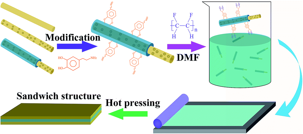 | ||
| Fig. 1 Schematic of the fabrication process of sandwich structure composites. | ||
2.5 Characterization
The morphology of fillers and cross-sectional images of composite films were determined by scanning electron microscopy (SEM, SU 8020) and transmission electron microscopy (TEM, JEM-2010F). X-ray diffraction (XRD, Empyrean, PANalytical, Holland) was used to study the crystal structures of fillers and composites using a Cu Kα source. The dielectric performance of composite films was characterized by a broadband dielectric spectrometer (Novocontrol GmbH, Germany) from frequency 100 to 107 Hz. The D–E loops and current density were characterized by a Precision LC ferroelectric test system (Radiant Technologies, USA).3. Results and discussion
BCZT, BCZT + Ag and BCZT + Ag@Al2O3 nanofibers were prepared by electrospinning and coaxial spinning. The XRD patterns of three inorganic fillers are displayed in Fig. 2a–c. In Fig. 2a, the diffraction peaks at 2θ = 22.12°, 31.52°, 38.81°, 45.17°, 50.80°, 56.10°, 65.76°, 71.42°, 74.75°, 79.21° and 83.45° can be indexed to the (100), (110), (111), (200), (210), (211), (220), (300), (310), (311) and (222) reflections of BCZT, respectively. In addition to the diffraction peaks of BCZT, the diffraction peaks of Ag can be seen in Fig. 2b. For BCZT + Ag@Al2O3, besides the diffraction peaks of BCZT and Ag, the diffraction peaks of Al2O3 can also be seen in Fig. 2c. In order to better prove the existence of various elements, EDS studies were performed (illustrations of Fig. 2a–c). Consistent with the XDR results, the elemental signals of Ba, Ca, Zr and Ti appeared in BCZT. The elemental signals of Ag appeared in BCZT + Ag. The elemental signals of Al appeared in BCZT + Ag@Al2O3. Observation of the morphologies of BCZT, BCZT + Ag and BCZT + Ag@Al2O3 indicated that they have large aspect ratios. As shown in the SEM image, BCZT and BCZT + Ag exhibited average diameters of about 200 nm (Fig. 2d and e). BCZT + Ag@Al2O3 was synthesized via a coaxial spinning method, with a diameter of about 260 nm in which the outer diameter was about 30 nm (Fig. 2f). In order to better observe the core–shell structure of BCZT + Ag@Al2O3, higher magnification TEM images and elemental mappings are shown in Fig. 2g. Moreover, BCZT + Ag has a rougher surface compared with that of BCZT and BCZT + Ag@Al2O3, which is due to the addition of Ag particles (illustrations of Fig. 2d–f). The morphology and size of the Ag particles have been studied in previous study, and were reported to be 80 nm spherical particles.29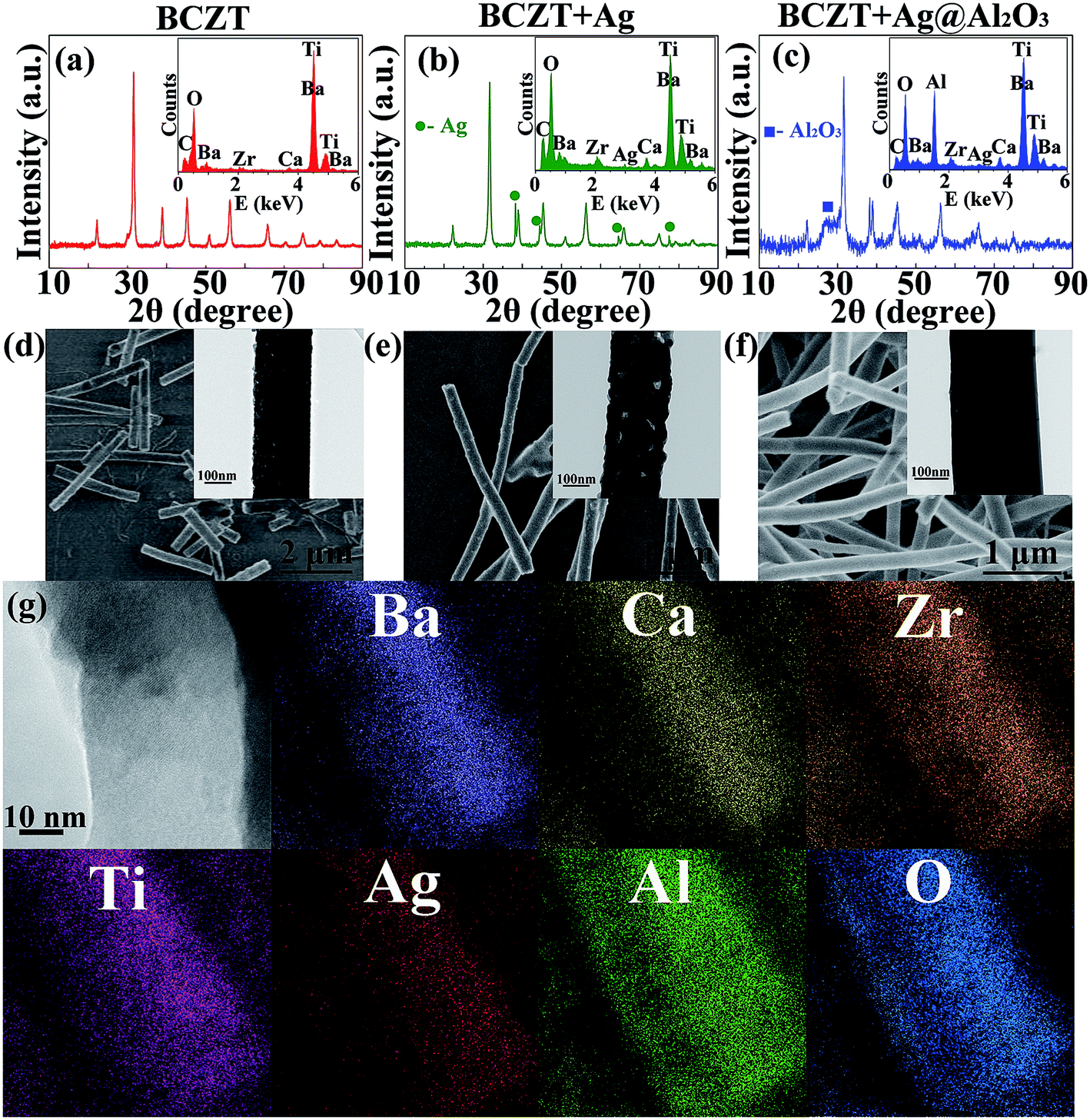 | ||
| Fig. 2 XRD patterns of (a) BCZT, (b) BCZT + Ag, (c) BCZT + Ag@Al2O3, and SEM images of (d) BCZT, (e) BCZT + Ag, (f) BCZT + Ag@Al2O3. The corresponding EDS spectra are shown in the insets in (a)–(c); the corresponding TEM diagrams are given in the insets of (d)–(f). (g) The higher magnification TEM images and elemental mappings of BCZT + Ag@Al2O3. | ||
Fig. 3 shows the XRD patterns of polymer and filler/PVDF composites. It can be seen that the XRD pattern of the pure PVDF and PMMA/PVDF blend polymer exhibited wide humps at 15°–20°, which was a feature of PVDF and PMMA. Similarly, the diffraction peaks of the fillers and PVDF can be seen in the filler/PVDF composites.
 | ||
| Fig. 3 XRD pattern of polymer and filler/PVDF composites. | ||
Fig. 4 shows the dielectric constant, dielectric loss tangent and conductivity of the polymer and filler/PVDF composites at 10 Hz. Compared with PMMA/PVDF polymer, PVDF has the highest dielectric constant. This is attributed to the introduction of the linear polymer PMMA, which has a lower dielectric constant (ε = 3.5).30,31 However, the dielectric loss tangent and conductivity of the PMMA/PVDF polymer were also reduced due to the introduction of PMMA. The filler/PVDF composites have a higher dielectric constant than the polymer because of the higher dielectric constant of ferroelectric materials contributing to the interfacial accumulation of charges.6 The BCZT + Ag/PVDF composites have the highest dielectric constant because the addition of Ag particles with good conductivity increases the charge accumulation at the interface. However, the Ag particles caused the BCZT + Ag/PVDF composites to have the highest dielectric loss and conductivity. Interestingly, the dielectric constant of BCZT + Ag@Al2O3/PVDF is lower than that of the other two composites. This is because (i) the addition of the Al2O3 shell reduces the polarization of the interface32 and (ii) Al2O3 as an insulating layer effectively inhibits the space charge transport between fillers and the matrix.33 Moreover, the Al2O3 shell layer reduces the dielectric loss and conductivity of the composites, which was confirmed by the results of Fig. 4b and c. This provides favorable conditions for improving the breakdown and energy densities of the composites. These results indicate that BCZT + Ag can provide larger polarization, and BCZT + Ag@Al2O3 can effectively reduce dielectric loss.
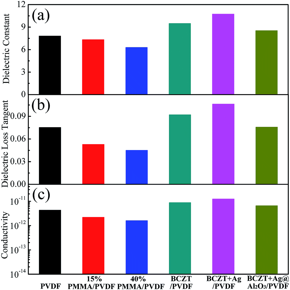 | ||
| Fig. 4 Dielectric constant (a), dielectric loss tangent (b) and conductivity (c) of polymer films and composite films at 10 Hz. | ||
As shown in Fig. 5a, the current densities of the polymers were ranked in the order of PVDF > 15% PMMA/PVDF > 40% PMMA/PVDF, which indicates that the addition of PMMA of the blend polymer significantly influences the current density of their polymer. Among the composites, the BCZT + Ag@Al2O3/PVDF composites exhibited the lowest current density, while BCZT + Ag/PVDF composites had the highest current density. The reason for this may be the introduction of Ag into BCZT + Ag that increases the current density of the composites and the rough surface of BCZT + Ag (as shown in Fig. 2e), which may lead to cavities or defects at the interface between the filler and the matrix. On the contrary, the non-crystalline Al2O3 shell in BCZT + Ag@Al2O3 makes the fiber surface smooth (as shown in Fig. 2f), while the insulated Al2O3 shell also reduces the possibility of charge passing through the core–shell nano-filler into the polymer matrix, which reduces the current density of the composites.34 These results are also consistent with the dielectric loss tangent.
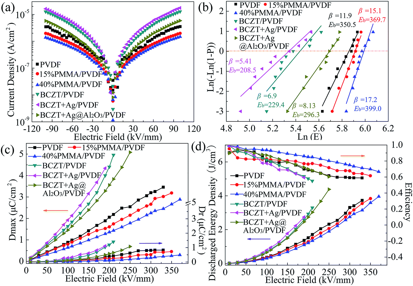 | ||
| Fig. 5 Current density (a), Weibull distribution (b), maximum polarization (Dmax) and remnant polarization (Dr) (c), energy density and efficiency (d) of polymer films and composite films. | ||
The breakdown strength plays a vital role in improving the energy density of dielectric capacitors. The characteristic breakdown strength of the polymer and composites was analyzed using the Weibull distribution function. It can be seen from Fig. 5b that the breakdown strength of the polymer was maintained at a high level (350.5–399.0 kV mm−1) and the breakdown strength of the PMMA/PVDF blend polymer was higher than that of PVDF. This is because PMMA with low dielectric and linear characteristics reduces the loss, conductivity and current density of PVDF. Also, previous reports show that the addition of PMMA to PVDF can induce the phase transition from the α phase to β phase or γ phase, which is also beneficial for improving the breakdown field of the polymer film.30,35 However, the breakdown strength of the composites are lower than that of the polymer. The BCZT + Ag@Al2O3/PVDF composite has higher breakdown strength than the other composites, while the BCZT + Ag/PVDF has the lowest. First, due to the large dielectric difference between the high dielectric fillers and the polymer matrix, electric field distortion easily occurs at the interface, resulting in the breakdown of the composite films. The local electric field distortion can be reduced by adding a buffer-dielectric constant Al2O3 interface between BCZT + Ag and PVDF.6 Second, as mentioned above, Al2O3 as an insulating layer can limit the carrier migration in the interface between BCZT + Ag and the PVDF matrix, thus reducing the loss and current density of the composite films.33
The hysteresis loops show the dielectric properties at high applied fields.6 The maximum displacement (Dmax) and remnant displacement (Dr) can be obtained by the displacement (D)-electric field (E) curve, and the corresponding energy density and efficiency can be obtained by eqn (1) and eqn (2) as follows:
| U = ∫EdD | (1) |
 | (2) |
It can be seen from the above results that the polymer, especially with the addition of PMMA, has the advantages of high breakdown strength and efficiency, but also has the disadvantages of low dielectric constant and energy density. However, the composites have the advantages of high dielectric constant and energy density under the same electric field but have the disadvantages of low breakdown strength and efficiency. Although the breakdown strength and efficiency of the composites are improved by modifying fillers (as BCZT + Ag@Al2O3), they are still not as good as the polymer. In other words, a separate pursuit of high breakdown strength or high polarization of energy storage materials cannot achieve high energy storage composites. Sandwich-structured composites can combine the advantages of each layer, and adjust the electric field distribution in composites because of the dielectric properties of the composites in each layer. In this study, in order to obtain composites with higher energy density, the PVDF-based composites (BCZT + Ag/PVDF and BCZT + Ag@Al2O3/PVDF) with high dielectric constant were chosen as the middle layers of the sandwich-structure composites, and the polymer with high breakdown was chosen as the outer layer. The PVDF/BCZT + Ag/PVDF/PVDF (defined as 0-32-0), 15% PMMA/PVDF/BCZT + Ag/PVDF/15% PMMA/PVDF (defined as 15-32-15), 40% PMMA/PVDF/BCZT + Ag/PVDF/40% PMMA/PVDF (defined as 40-32-40), PVDF/BCZT + Ag@Al2O3/PVDF/PVDF (defined as 0-33-0), 15% PMMA/PVDF/BCZT + Ag@Al2O3/PVDF/15% PMMA/PVDF (defined as 15-33-15), 40% PMMA/PVDF/BCZT + Ag@Al2O3/PVDF/40% PMMA/PVDF (defined as 40-33-40) sandwich-structure composites were prepared.
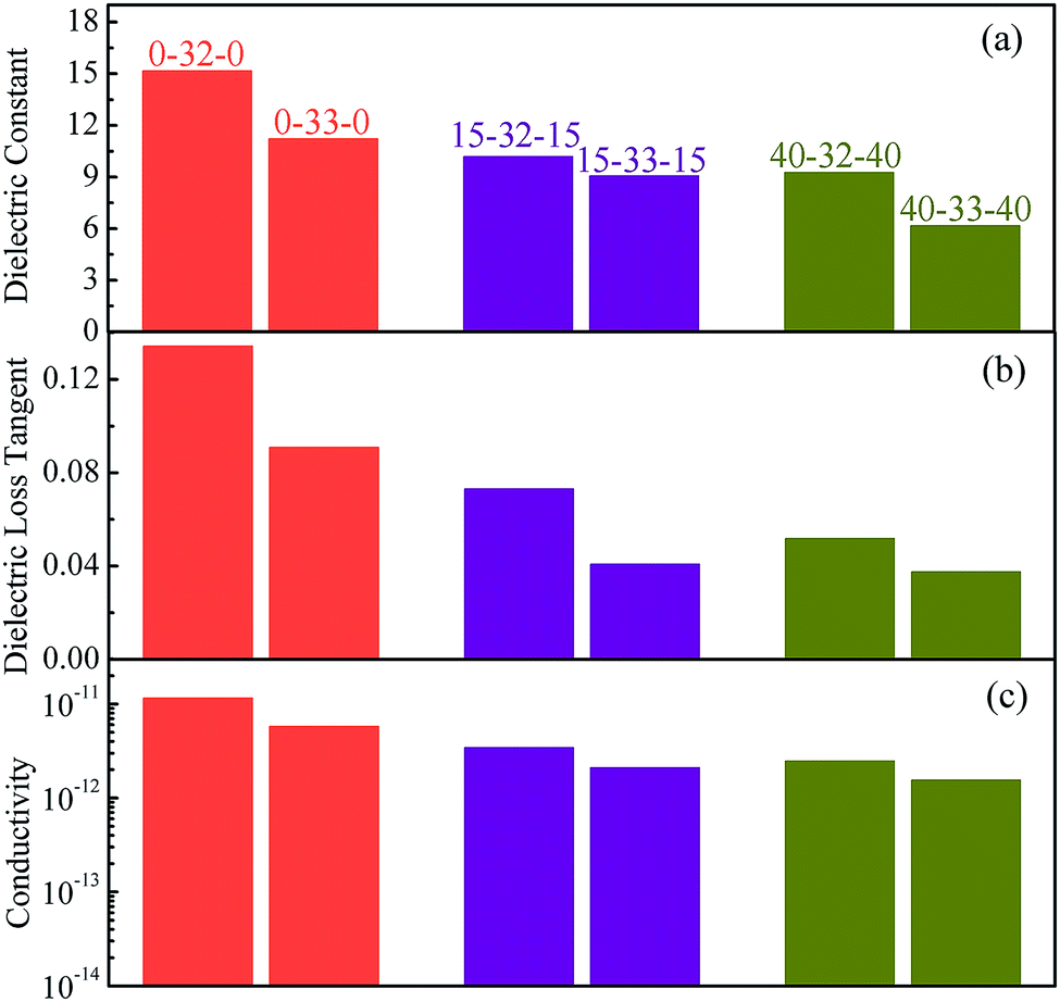
Fig. 6 shows the dielectric properties of the sandwich-structure composites. When the middle layer is the same, the polymer as the outer layer plays an important role in the dielectric properties of the composites. Fig. 6a shows that the dielectric constant of the sandwich structure composite decreases as the content of PMMA increases in the polymer outer layers, as expected. However, when the same polymer is selected as the outer layer, the dielectric properties of the composites as the middle layer affect the sandwich structure composites. Therefore, the composites with BCZT + Ag/PVDF as the middle layer have a higher dielectric constant than that with BCZT + Ag@Al2O3/PVDF as the middle layer, which is consistent with the law of dielectric constants of single-layer composites. It is noteworthy that the dielectric constant of the sandwich composites is slightly higher than that of single-layer structures, which may be because in sandwich structures, charges are stored at the interface of two heterogeneous films. Thus, the dielectric of the sandwich-structure composites is improved.36,37 Fig. 6b and c show the dielectric loss and conductivity of the sandwich structure composites, respectively. Consistent with the law of dielectric constant, the composites with PVDF as the outer layer have the highest dielectric loss and conductivity in the same middle layer, and the composites with BCZT + Ag/PVDF as the middle layer have higher dielectric loss and conductivity than that with BCZT + Ag@Al2O3/PVDF. In particular, the use of the 40% PMMA/PVDF polymer as the outer layer or the selection of BCZT + Ag@Al2O3 as the filler in the middle layer can be more effective at reducing the loss of the composite, which is advantageous for the breakdown of the composite and the improvement of the energy storage performance.
 | ||
| Fig. 6 Dielectric constant (a), dielectric loss tangent (b) and conductivity (c) of composite films with the sandwich structure at 10 Hz. | ||
For the sandwich structure composites, the cross-sectional SEM microscopy, current density and breakdown properties are shown in Fig. 7. The thickness ratio between layers of sandwich structure composites is about 1:1:1, which can be found from the cross-sectional SEM microscopy of 40-32-40 and 40-33-40 given in Fig. 7a and b. The current density of the sandwich structure composites is lower than that of the corresponding middle layer composites, which occurs because the polymer as the outer layer has lower current density and hinders the movement of the free electrons of the middle layer throughout the sandwich structure. When the middle layer composites are the same, the current density of the 40% PMMA/PVDF as the outer layer sandwich-structure composite is the lowest. When the outer layer polymer selection is consistent, the current density of the composites with BCZT + Ag/PVDF as the middle layer is higher than that with BCZT + Ag@Al2O3/PVDF as the middle layer. Such results are related to the introduction of linear PMMA and the core–shell structure of BCZT + Ag@Al2O3.
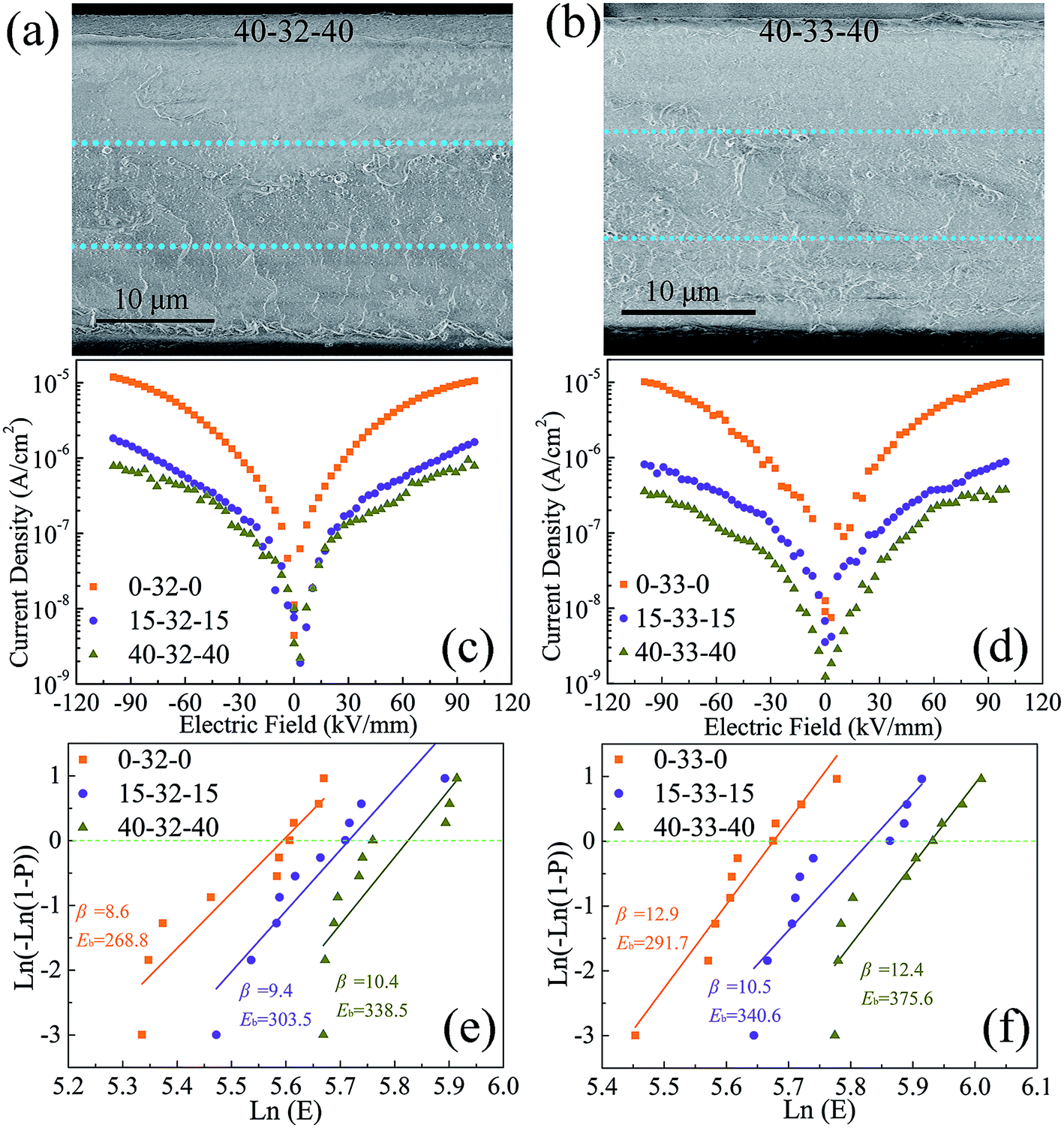 | ||
| Fig. 7 Cross-sectional SEM microscopy (a and b), current density (c and d), Weibull distribution (e and f) of sandwich structure composites. | ||
Due to the difference in the dielectric constant between the composite layer (εc) and the polymer layer (εp) in the sandwich structure, the electric field will be redistributed between the different layers. The relationship between the electric field of the composite film (Ec) and that of the outer polymer film (Ep) can be derived from the series capacitor model, as eqn (3).37
| Ec × εc = Ep × εp | (3) |
According to the above equation, when the sandwich structure composites are subjected to an electric field, the polymer layer will withstand a higher electric field because it has a lower dielectric constant. The polymer layer itself has a higher breakdown strength, especially the polymer containing PMMA, and the middle layer having a higher dielectric constant will be subjected to a lower electric field. However, the outer layer can protect the middle layer from premature breakdown.37 In addition, it has been found in previous studies that the interfaces between the layers in the sandwich structure have an effect on preventing the development of the electric branch, which is one of the reasons the sandwich structure has a high breakdown strength.23,38–40 As expected, when the middle layer is the same, the sandwich-structure composite with 40% PMMA/PVDF as the outer layer has a high breakdown strength. When the outer layer is the same, the breakdown strength of the sandwich-structure composites with BCZT + Ag@Al2O3/PVDF as the middle layer is higher.
Fig. 8 shows the Dmax, Dr, energy density and efficiency of sandwich structure composites. At the same applied electric field, when the outer layer is the same the sandwich structure composites with BCZT + Ag/PVDF as the middle layer show higher Dmax (attributed to the larger dielectric constant of the middle layer) and Dr (attributed to the larger dielectric loss and conductivity of the middle layer). When the same middle layer is chosen at the same electric field, the sandwich structure composites with PVDF as the outer layer have the highest Dmax and Dr, which is attributed to the larger dielectric constant, dielectric loss and conductivity. In contrast, the sandwich structure composites with PMMA/PVDF as the outer layer have lower Dmax and Dr. However, the high Dr reduces the discharge energy density and efficiency. For instance, at 260 kV mm−1, the 0-32-0 composite has the highest Dmax (7.37 μC cm−3) and Dr (2.22 μC cm−3), which results in its efficiency being only 48.0%. It is worth noting that when the content of PMMA in the polymer outer layer is less than 40%, the sandwich structure composites with BCZT + Ag@Al2O3/PVDF as the middle layer have higher energy density because it can be polarized at a higher field strength. Although the 40-32-40 composite has the highest energy density (U = 8.48 J cm−3, η = 65.9% at 330 kV mm−1) of all sandwich-structure composites, 40-33-40 not only has a similar energy density to 40-32-40 but also has the highest efficiency (U = 7.23 J cm−3, η = 75.8% at 370 kV mm−1). In summary, the polymer outer layer with a high content of PMMA can improve the breakdown strength and efficiency of the composite while reducing its polarization. The performance of composites as the middle layer has an important influence on the energy density of sandwich composites.
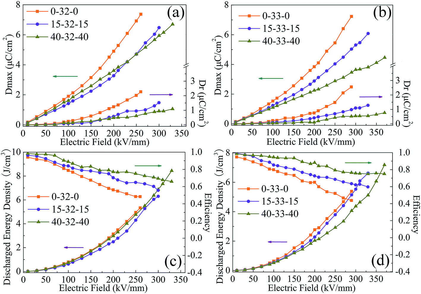 | ||
| Fig. 8 Maximum polarization (Dmax) and remnant polarization (Dr) (a and b), energy density and efficiency (c and d) of composite films with the sandwich structure. | ||
4. Conclusions
Novel core–shell structure fillers consisting of BCZT, Ag and Al2O3 were fabricated by electrospinning. For the sandwich structure composites where the outer layer is the polymer layer and the middle layer is the composite, there is a higher breakdown strength, endowing sandwich-structure composites with much higher energy density and efficiency; the 40-33-40 composite has the energy density of 7.23 J cm−3 and efficiency above 75.8% at 370 kV m−1. This study provides a new strategy for fabricating sandwich-structure composites with lower dielectric loss, conductivity and current density, and improved breakdown strength, energy density and efficiency.Conflicts of interest
The authors declare that they have no conflict of interest.Acknowledgements
This research was funded by National Natural Science Foundation of China (No. 51977050, 51807042, 51807041), Natural Science Foundation of Heilongjiang Province of China (No. TD2019E002), Fundamental Research Foundation for Universities of Heilongjiang Province (No. LGYC2018TD001, LGYC2018JC020).References
- M. S. Whittingham, MRS Bull., 2008, 33, 411–419 CrossRef CAS.
- Y. F. Wang, L. X. Wang, Q. B. Yuan, J. Chen, Y. J. Niu, X. W. Xu, Y. T. Cheng, B. Yao, Q. Wang and H. Wang, Nano Energy, 2017, 44, 364–370 CrossRef.
- X. Huang and P. Jiang, Adv. Mater., 27, 546–554 CrossRef CAS.
- Z. B. Pan, L. M. Yao, G. L. Ge, B. Shen and J. W. Zhai, J. Mater. Chem. A, 2018, 6, 14614–14622 RSC.
- Z. Yao, Z. Song, H. Hao, Z. Yu, M. Cao, S. Zhang, M. T. Lanagan and H. Liu, Adv. Mater., 2017, 29, 1601727 CrossRef.
- Z. B. Pan, L. M. Yao, J. W. Zhai, K. Yang, B. Shen and H. T. Wang, ACS Sustainable Chem. Eng., 2017, 5, 4707–4717 CrossRef CAS.
- S. Wu, W. P. Li, M. R. Lin, Q. Burlingame, Q. Chen and A. Payzant, Adv. Mater., 2013, 25, 1734–1738 CrossRef CAS.
- S. Wu, M. R. Lin, Q. Burlingame and Q. M. Zhang, Appl. Phys. Lett., 2014, 104, 072903 CrossRef.
- Y. Feng, W. L. Li, Y. F. Hou, Y. Yu, W. P. Cao, T. D. Zhang and W. D. Fei, J. Mater. Chem. C, 2015, 3, 1250–1260 RSC.
- B. C. Luo, X. H. Wang, Y. P. Wang and L. T. Li, J. Mater. Chem. A, 2014, 2, 510–519 RSC.
- Y. F. Feng, B. Miao, H. H. Gong, Y. C. Xie, X. Y. Wei and Z. C. Zhang, ACS Appl. Mater. Interfaces, 2016, 8, 19054–19065 CrossRef CAS PubMed.
- Z. B. Pan, L. M. Yao, J. W. Zhai, B. Shen, S. H. Liu, H. T. Wang and J. H. Liu, J. Mater. Chem. A, 2016, 4, 13259–13264 RSC.
- X. Y. Huo, W. P. Li, J. J. Zhu, Y. Li, L. H. Lou and Y. J. Zhu, J. Phys. Chem. C, 2016, 119, 25786–25791 CrossRef.
- S. B. Luo, S. H. Yu, R. Sun and C. P. Wong, ACS Appl. Mater. Interfaces, 2014, 6, 176–182 CrossRef CAS.
- S. H. Liu, S. X. Xue, W. Q. Zhang, J. W. Zhai and G. H. Chen, J. Mater. Chem. A, 2014, 2, 18040–18046 RSC.
- Z. M. Dang, M. S. Zheng and J. W. Zha, Small, 2016, 12, 1688–1701 CrossRef CAS.
- D. Guo, K. Cai and Y. L. Wang, J. Mater. Chem. C, 2017, 5, 2531–2541 RSC.
- P. H. Hu, Z. Y. Jia, Z. H. Shen, P. Wang and X. R. Liu, Appl. Surf. Sci., 2018, 441, 824–831 CrossRef CAS.
- Y. C. Xie, Y. Y. Yu, Y. F. Feng, W. R. Jiang and Z. C. Zhang, ACS Appl. Mater. Interfaces, 2017, 9, 2995–3005 CrossRef CAS.
- R. Guo, H. Luo, W. W. Liu, X. F. Zhou, L. Tang, K. C. Zhou and D. Zhang, Phys. Chem. Chem. Phys., 2018, 20, 18031–18037 RSC.
- Z. B. Pan, L. M. Yao, J. W. Zhai, D. Z. Fu, B. Sheng and H. T. Wang, ACS Appl. Mater. Interfaces, 2017, 9, 4024–4033 CrossRef CAS.
- Z. B. Pan, Z. B. Pan, J. J. Liu, X. Y. Liu, F. P. Pi, J. W. Chen, B. Shen and J. W. Zhai, J. Mater. Chem. C, 2019, 7, 405–413 RSC.
- Y. F. Wang, J. Chen, Y. Li, Y. J. Niu, Q. Wang and H. Wang, J. Mater. Chem. A, 2019, 7, 2965–2980 RSC.
- P. H. Hu, Y. Shen, Y. H. Guan, X. H. Zhang, Y. H. Lin and Q. M. Zhang, Adv. Funct. Mater., 2014, 24, 3172–3178 CrossRef CAS.
- Q. Chi, T. Ma, Y. Zhang, Q. G. Chen, C. H. Zhang, Y. Cui, T. D. Zhang, J. Q. Lin, X. Wang and Q. Q. Lei, ACS Sustainable Chem. Eng., 2017, 6, 403–412 CrossRef.
- Q. Li, L. Chen, M. R. Gadinski, S. H. Zhang, G. Z. Zhang, H. U. Li, E. Iagodkine, A. Haque, L. Q. Chen, T. N. Jackson and Q. Wang, Nature, 2015, 523, 576–579 CrossRef CAS.
- Q. G. Chi, T. Ma, Y. Zhang, Y. Cui, C. H. Zhang, J. Q. Lin, X. Wang and Q. Q. Lei, J. Mater. Chem. A, 2017, 5, 16757–16766 RSC.
- X. H. Xia, J. Zeng, L. K. Oetjen, Q. G. Li and Y. N. Xia, J. Am. Chem. Soc., 2012, 134, 1793–1801 CrossRef CAS.
- Y. Cui, T. D. Zhang, Y. Feng, C. H. Zhang, Q. G. Chi, Y. Q. Zhang, Q. G. Che, X. Wang and Q. Q. Lei, Composites, Part B, 2019, 177, 107429 CrossRef.
- B. C. Luo, X. H. Wang, H. X. Wang, Z. M. Cai and L. T. Li, Compos. Sci. Technol., 2017, 151, 94–103 CrossRef CAS.
- E. Y. Shin, H. J. Cho, S. Jung, C. Yang and Y. Y. Noh, Adv. Funct. Mater., 2017, 28, 1704780 CrossRef.
- Y. Shen, D. S. Shen, X. Zhang, J. Y. Jiang, Z. K. Dan, Y. Song, Y. H. Lin, M. Li and C. W. Nan, J. Mater. Chem. A, 2016, 4, 8359–8365 RSC.
- M. Samet, V. Levchenko, G. Boiteux, G. Seytre, A. Kallel and A. Serghei, J. Chem. Phys., 2015, 142, 2027–2037 CrossRef.
- D. Kang, G. Y. Wang, Y. H. Huang, P. K. Jiang and X. Y. Huang, ACS Appl. Mater. Interfaces, 2018, 10, 4077–4085 CrossRef CAS.
- Z. Zhou, J. Carr, M. Mackey, K. Z. Yin, D. Schuele, L. Zhu and E. Baer, J. Polym. Sci., Part B: Polym. Phys., 2013, 51, 978–991 CrossRef CAS.
- P. H. Hu, J. J. Wang, Y. Shen, Y. H. Guang, Y. H. Lin and C. W. Nan, J. Mater. Chem. A, 2013, 1, 12321–12326 RSC.
- Y. Wang, Y. Hou and Y. Deng, Compos. Sci. Technol., 2017, 145, 71–77 CrossRef CAS.
- W. W. Nian, Z. Wang, T. Wang, Y. J. Xiao and H. N. Chen, Ceram. Int., 2018, 44, S50–S53 CrossRef CAS.
- Y. F. Wang, J. Cui, Q. B. Yuan, Y. J. Niu, Y. Y. Bai and H. Wang, Adv. Mater., 2015, 27, 6658–6666 CrossRef CAS.
- L. Yao, D. R. Wang, P. H. Hu, B. Z. Han and Z. M. Dang, Adv. Mater. Interfaces, 2016, 3, 1600016 CrossRef.
| This journal is © The Royal Society of Chemistry 2019 |