 Open Access Article
Electrochemical fabrication and evaluation of a self-standing carbon nanotube/carbon fiber composite electrode for lithium-ion batteries†
Yi-Hung Liu *a,
Heng-Han Lina,
Tsung-Yu Tsaia and
Chun-Han Hsu
 *b
*b
aDepartment of Chemical and Materials Engineering, National Central University, No. 300, Zhongda Road, Zhongli District, Taoyuan 32001, Taiwan. E-mail: yhliu@ncu.edu.tw
bGeneral Education Center, National Tainan Junior College of Nursing, 78, Sec. 2, Minzu Rd., Tainan 700, Taiwan. E-mail: chunhanhsu@gmail.com
First published on 16th October 2019
Abstract
A binder-free self-standing carbon nanotube (CNT)/carbon fiber (CF) composite electrode, which has been developed using an electrophoretic deposition approach, was utilized as a lithium-ion battery anode. The morphology of the CNT/CF composite has been examined using scanning electron microscopy, and the results indicated that a CNT layer uniformly deposited on the CFs. The thickness and density of the CNT layer increased as the electrodeposition time increased, while overdeposition caused the CNT layer to exfoliate. Electrochemical evaluation revealed that the specific capacity, cycling stability, and rate capability of the CNT/CF anode were superior to those of the CF anode. The electrochemical impedance analysis results further revealed that the solid/electrolyte interface resistance and interface resistance induced by the oxygen-containing surface functional groups of CFs dominated the impedance of the anode. However, these resistance values could be potentially reduced via CNT surface modification, which could lead to the enhanced electrochemical performance of the CNT/CF anode. Our findings should open new avenues for the potential use of the CNT/CF composite as a self-standing anode for lithium-ion battery applications.
Introduction
Carbon fibers (CFs) have been recently attracting significant attention in industrial applications owing to their diverse intrinsic material properties, including their light weight, good mechanical strength, favorable electrical conductivity, thermal tolerance, chemical stability, and flexibility.1–3 Currently, CFs are used for many sports tools, automobiles, and aircraft, because they allow light and flexible body design without sacrificing mechanical strength. In addition, CFs are utilized as matrix materials to form hybrids with other materials for fabricating CF-reinforced polymer composites (CFRPs) with improved mechanical and thermal properties. Intense research efforts have been made toward improving the interfacial properties of CFs because they were determined to benefit the ultimate mechanical properties of CFRPs. Moreover, CFs have been subjected to various surface treatment technologies, such as thermal oxidation,4,5 chemical oxidation,6,7 electrochemical oxidation,8,9 and plasma modification.1,10 In addition, depositing carbon nanotubes (CNTs) on CF/vinyl ester composite laminates using the spraying technique has been determined to significantly increase the mechanical properties of the laminates. This demonstrated that the CNT deposition technology could be a promising method for improving the interfacial compatibility between CFs and bulk materials.11,12 As an alternative deposition approach, immersing CFs in CNT suspensions has been proposed to improve interfacial friction, chemical bonding, and resin toughening of nanostructured CF/epoxy composites.13 Boccaccini et al. proposed a different method: the electrophoretic deposition (EPD) technique for CNT deposition on composite structures14 owing to its various advantages, including the low cost, process simplicity, controllable uniformity and thickness of deposits, microstructural homogeneity, and possibility of depositing CNTs on complex-shaped substrates.15–17In addition to CFRPs, CFs can be used for secondary battery applications. For example, CFs have been utilized as electrical conductive materials, and have been combined with electrode active materials to obtain CF/active material composite electrodes for lithium-ion battery applications.18,19 Most previously published papers mentioned the use of CFs as conductive agent for composite electrodes, while the direct use of CFs as self-standing electrode has rarely been investigated. Takami et al. have studied graphitized CFs as electrode active material.20 However, CFs were mixed with binders and coated on copper current collectors, which were still dissimilar to the self-standing electrode design, and thus, complex electrode fabrication processes have been inevitable. Therefore, the direct use of CFs as self-standing electrodes, i.e., avoiding the use of binders, conductive agents, or even metal current collectors in electrode design, should be taken into consideration and investigated.
To explore the potential electrochemical capability of CFs, we fabricated a binder-free self-standing anode for lithium-ion battery application where CFs were used as both current collectors and active materials. A facile and simple EPD technique was adopted to develop a self-standing CNT/CF composite anode. Since development of several composites have been reported to exhibit outstanding performance for supercapacitor,21–23 lithium ion battery,24,25 and biosensor26,27 applications; therefore, we herein attempted to enhance electrode performance of lithium ion battery using the CNT/CF composite. The electrochemical behaviors of the CNT/CF and CF anodes were evaluated using charge/discharge tests and electrochemical impedance spectroscopy (EIS) measurements. Decorating CFs with CNT layers was determined to stabilize the properties at the CF electrode/electrolyte interface, which resulted in the significant improvement in the cycling stability and rate capability of the electrode.
Experimental section
Preparation of CNT/CF composite
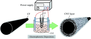
A CF-tow (Formosa Plastic Corporation, Taiwan) that contained 12![[thin space (1/6-em)]](https://www.rsc.org/images/entities/char_2009.gif) 000 single fibers was used as substrate for fabricating CF-based electrodes. To prepare CNT/CF composite electrodes, 1 mg multi-wall CNTs was first added to 100 mL sodium hydroxide solution in methanol (concentration of 1 wt%), and then the mixture was dispersed via magnetic stirring for 2 h. Afterward, the CFs were partially dipped into the CNT-containing solution, and the undipped portion was electrically connected to a GPS-4303 (GW-Instek, Taiwan) power supply source, to carry out the EPD of CNTs. In this electrolytic system, carbon paper was used as counter electrode to balance the electrical charge of the CF working electrode. Schematic diagram of the EPD process is shown in Fig. 1. During the process, the applied current was maintained at 0.02 A, and the deposition time was varied from 5, to 10 and 20 min. Then, the electrochemically treated CFs were cleaned with deionized water and dried at 100 °C for 2 h, followed by calcination at 400 °C to remove impurities.
000 single fibers was used as substrate for fabricating CF-based electrodes. To prepare CNT/CF composite electrodes, 1 mg multi-wall CNTs was first added to 100 mL sodium hydroxide solution in methanol (concentration of 1 wt%), and then the mixture was dispersed via magnetic stirring for 2 h. Afterward, the CFs were partially dipped into the CNT-containing solution, and the undipped portion was electrically connected to a GPS-4303 (GW-Instek, Taiwan) power supply source, to carry out the EPD of CNTs. In this electrolytic system, carbon paper was used as counter electrode to balance the electrical charge of the CF working electrode. Schematic diagram of the EPD process is shown in Fig. 1. During the process, the applied current was maintained at 0.02 A, and the deposition time was varied from 5, to 10 and 20 min. Then, the electrochemically treated CFs were cleaned with deionized water and dried at 100 °C for 2 h, followed by calcination at 400 °C to remove impurities.
Material characterization and electrochemical evaluation
A JSM-7000F (JEOL, Japan) field emission scanning electron microscopy (FESEM) device and a Cary 600 Series (Agilent Technologies, USA) Fourier-transform infrared (FT-IR) spectroscope were used to carry out morphological and superficial characterization, respectively, of the CF and CNT/CF composite electrodes. To evaluate the electrochemical characteristics of the CF-based electrodes, a coin-type test cell (CR2032) was used. The 0.5 × 0.5 cm2 CF or CNT/CF electrode was placed in the test cell as working electrode, while lithium metal foil served as counter electrode. A polymer film comprising polyethylene and polypropylene was used as separator, and the electrolyte consisted of 1 M lithium hexafluorophosphate that was dissolved in a 1![[thin space (1/6-em)]](https://www.rsc.org/images/entities/char_2009.gif) :
:![[thin space (1/6-em)]](https://www.rsc.org/images/entities/char_2009.gif) 1 (v/v) mixture of ethylene carbonate and diethyl carbonate as solvent (Hopax, Taiwan). The test cells were assembled in a glove box filled with argon gas. Charge/discharge cycling tests of the assembled cells were performed using a BAT-750B (AcuTech Systems Co. Ltd., Taiwan) battery charge/discharge automatic test system, while cyclic voltammetry (CV) and alternating current (AC) impedance measurements of the cells were carried out using a PGSTAT 30 (Autolab, EcoeChemie, Switzerland) potentiostat/galvanostat equipped with EIS modules.
1 (v/v) mixture of ethylene carbonate and diethyl carbonate as solvent (Hopax, Taiwan). The test cells were assembled in a glove box filled with argon gas. Charge/discharge cycling tests of the assembled cells were performed using a BAT-750B (AcuTech Systems Co. Ltd., Taiwan) battery charge/discharge automatic test system, while cyclic voltammetry (CV) and alternating current (AC) impedance measurements of the cells were carried out using a PGSTAT 30 (Autolab, EcoeChemie, Switzerland) potentiostat/galvanostat equipped with EIS modules.
Results and discussion
To confirm the decoration of CNTs on the CFs, SEM analysis of the pristine and modified CFs was carried out. Fig. 2a illustrates the SEM image of the pristine CFs, which presented regular cylindrical shape and uniform size. According to the magnified image (see inset of Fig. 2a), the surface of CFs was relatively smooth, no visible deformation or cracks were detected, and the diameter of the CFs was estimated to be ∼6 μm. The FT-IR spectrum of the fibers is depicted in Fig. 2b. A sharp peak with relatively high absorbance can be identified at ∼1000 cm−1, and indicates the presence of ether functional groups (C–O–C stretching vibration) on the fiber surface. The oxygen-containing functional groups rendered the fiber surface hydrophilic, which facilitated the EPD of CNTs in aqueous solution.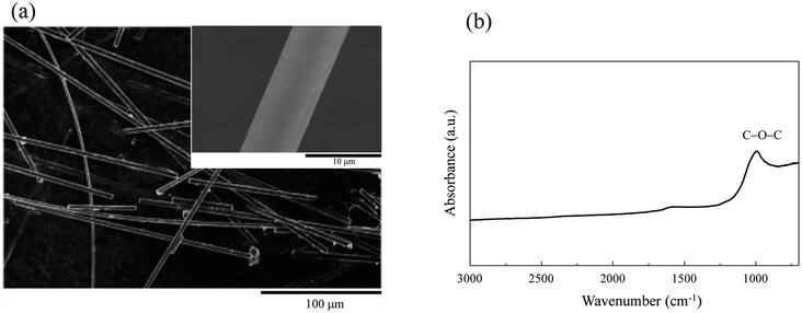 | ||
| Fig. 2 (a) Scanning electron microscopy image and (b) Fourier-transform infrared spectrum of pristine carbon fibers. | ||
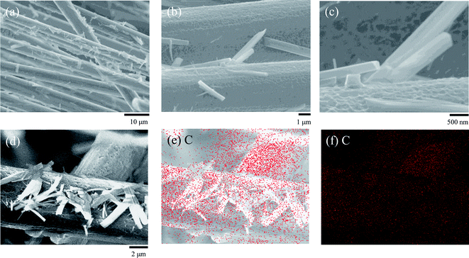
After the CFs were subjected to EPD, the presence of CNT aggregates was confirmed on the CFs surface, and the CNT/CF composites were obtained, as presented in Fig. 3a–d. The CNT aggregates obtained after 5 min of deposition (Fig. 3a) were sparsely distributed on the CFs and their orientation was random, which resulted in an irregular surface. As the deposition time was increased to 10 min, the CNT aggregates formed a dense layer and covered the CFs well (Fig. 3b). From the magnified image in Fig. 3c, it was confirmed that the needle-like CNTs on the CF surface were uniformly distributed and formed a dense layer. However, as the deposition time was increased to 20 min (Fig. 3d), the CNT layer started to exfoliate from the CFs and became partially attached between them. This could be attributed to that the CNT layer became thicker with poorer homogeneity after the overdeposition of CNTs,28,29 not being mechanically supported by the CFs. Overall, these findings revealed that CNTs could be effectively decorated on the CFs via EPD treatment at moderate deposition time.
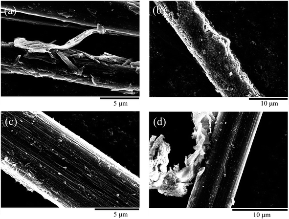 | ||
| Fig. 3 Scanning electron microscopy image of carbon nanotube/carbon fiber composite obtained using electrophoretic deposition times of (a) 5, (b) and (c) 10, and (d) 20 min. | ||
To confirm the CNT deposition properties, further investigations of the CNT/CF composites were carried out and the results are shown in Fig. 4. From the wide view of the CNT/CF composites (Fig. 4a), it was found that multiple CFs were uniformly deposited by the CNTs together with their aggregates, confirming satisfactory deposition efficiency of CNTs. As for the observation with higher magnification, see Fig. 4b and c, the surface of the CNT/CF composites was relatively rough, which was different from the pristine CFs with smoother surface (Fig. 2a). In addition, the CNT aggregates were found to extend from the CNT/CF surface, forming either a needle-like or a prismatic structure. Typical CNT/CF composites were further analysed via energy dispersive X-ray spectrometry (EDS), as shown in Fig. 4d–f. According to the uniform carbon mapping patterns, it is ascertained that either the rough composite surface or the aggregates were composed of carbon, namely the deposited CNTs.
Fig. 5a and b present the typical charge/discharge profiles for the CF and CNT/CF (5 min deposition) anodes, respectively. The first charge capacity (lithium insertion) of the CF anode attained ∼272 mA h g−1, while the subsequent discharge capacity (lithium extraction) was reduced to 260 mA h g−1. The unstable profiles and lower capacity could be ascribed to the oxygen-containing group of the CFs surface, which interfered with ion transport during the charge/discharge process. As the number of cycles increased, the discharge capacity tended to stabilize at 260 mA h g−1 despite of slight variation of capacity. By contrast, the CNT/CF anode exhibited much improved capacity, which corresponded to the stable charge/discharge profiles in Fig. 5b. The CNT-decorated layer of CFs could suppress the interaction between the oxygen-containing groups of the CFs and lithium ions, thus contributing to the enhanced reversible capacity of ∼340 mA h g−1 (0.2C) for the CNT/CF anode. In addition, its charge/discharge voltage was lower compared with that of the CF anode, which was beneficial for energy density of a battery. Despite that the discharge capacity of the CNT/CF anode was not surprisingly high, it is still worth noting that the self-standing anode exhibited a very stable and reversible electrochemical behavior in terms of lithium ion insertion/extraction without any assistance from binders and conductive agents. To further investigate the electrochemical behaviors for the two anodes, cyclic voltammetry was also carried out, as shown in Fig. 6. For the CNT/CF anode, remarkable cathodic peaks were observed at potential lower than 0.5 V during the first cathodic sweep (reduction process) and a broad anodic peak can be identified at around 0.5 V during the subsequent anodic sweep. In the second cycle, the intensity of the cathodic peaks reduced, while the anodic peak remained almost unchanged. It is indicated that the CNT/CF anode exhibited favorable electrochemical reversibility in terms of ion insertion/extraction despite the presence of irreversible reduction reaction due to the well-known solid electrolyte interface (SEI) formation. On the other hand, the CF anode showed similar electrochemical behaviors during the two cycle sweeps; however, the overall peak intensity was smaller than that of the CNT/CF anode. This finding revealed that the CNT/CF anode possessed improved charge/discharge capacity compared to the CF one, which is consistent with the results of Fig. 5.
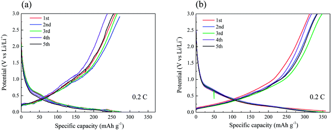 | ||
| Fig. 5 Typical charge/discharge profiles for (a) carbon fiber and (b) carbon nanotube/carbon fiber anodes. | ||
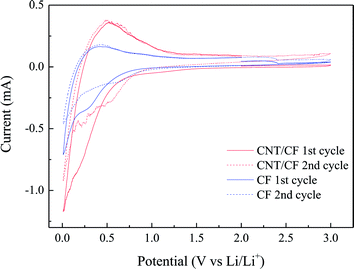 | ||
| Fig. 6 Cyclic voltammetry profiles for carbon fiber and carbon nanotube/carbon fiber anodes (scan rate: 0.2 mV s−1). | ||
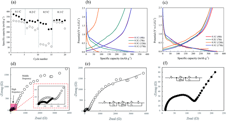
The cycling performance of the two CF-based anodes at various current rates was analyzed, and the results are depicted in Fig. 7a. The black and white circles here represent the CNT/CF and CF anodes, respectively. The rate performance of the CNT/CF anode was better than that of the CF anode, particularly at the high current rate of 0.5C. When the current rate returned to 0.1C (16th–20th cycles), the discharge capacity of the two anodes was similar, while it was still higher for the CNT/CF anode. This was also evidenced from the charge/discharge profiles of the CNT/CF and CF anodes, which are illustrated in Fig. 7b and c, respectively. When the current rate was increased, the significant decrease in capacity, increased polarization, and unstable profiles could be confirmed for the CF anode (Fig. 7b). On the other hand, the capacity decay and polarization at high current rates of the CNT/CF anode were potentially mitigated, and led to a discharge capacity value of ∼300 mA h g−1 even at 0.5C (Fig. 7c). Moreover, the profiles of the CNT/CF anode were more stable than those of the CF anode, which supported the electrochemical stability of the CNT/CF anode when operated at high current rates. To further understand the improved electrochemical performance of the CNT/CF anode compared with the CF one, AC impedance analysis tests were carried out for the two anodes, and the results are illustrated in Fig. 7d. The EIS spectrum of the CF anode consisted of two semicircles at high and middle frequencies together with an extended sloping line, while the spectrum of the CNT/CF anode only included one semicircle. Consequently, it was concluded that the internal resistance of the CF anode was much higher than that of the CNT/CF anode. The EIS spectra of the CF and CNT/CF anodes were further fitted with equivalent circuit models and the results are presented in Fig. 7e and f, respectively. The fitting findings revealed that the EIS results of both anodes followed the proposed models well despite the different models used for the two anodes. The model for the CF anode was more complicated, and contained an equivalent series resistance (Rs), a SEI resistance (RSEI), an interfacial resistance (Rint), and a charge transfer resistance (Rct). However, Rint was neglected when fitting the CNT/CF anode. The presence of Rint of the CF anode could be attributed to the interference of the polar functional groups (C–O–C) on the CF surface, as indicated in the FT-IR spectrum presented in Fig. 2b. This can also be evidenced from the FT-IR spectrum of the CNT/CF composite, showing much reduced peak intensity for the polar functional groups (∼1000 cm−1) (Fig. S1†). According to the fitting results (Table S1†), it is known that RSEI and Rint dominated the impedance behaviors. The resistance value of RSEI of the CNT/CF anode was much smaller than that of the CF anode, and its Rint can be neglected. This indicated that the surface modifications caused by the CNTs that were used to decorate the CFs were able not only to eliminate the influence of the surface functional groups but also to prevent the overgrowth of the SEI film. These findings should account for the stable and improved electrochemical performance of the CNT/CF anode, as illustrated in Fig. 5–7. The cycling performance at 0.1C for the two anodes were also evaluated, as shown in Fig. 8. The initial capacity of the CNT/CF anode reached ∼400 mA h g−1 and it slightly reduced to ∼370 mA h g−1 at the 23rd cycle, which was higher than the initial capacity of the CF anode (∼350 mA h g−1). In addition, after the 15th cycle, the CNT/CF capacity tended to stabilize, while the capacity remarkably decayed for the CF anode, indicating that the CNT/CF anode had better cycling stability than the other one. This result also agrees well with the above discussion.
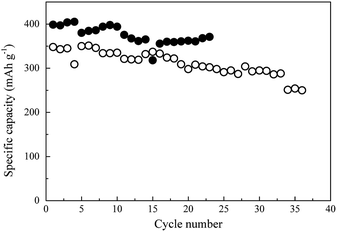 | ||
| Fig. 8 Cycling performance at 0.1C for carbon fiber (○) and carbon nanotube/carbon fiber (●) anodes. | ||
Conclusions
In conclusion, a CNT/CF composite anode has been developed using a simple EPD approach. Successful CNT surface modification of CFs was achieved at moderate deposition time, while the overdeposition of CNTs resulted in exfoliation. Both the CNT/CF composite and CFs could be directly used as anode materials for lithium-ion batteries without using any binders or conductive agents. Compared with the CF anode, the CNT/CF one demonstrated superior electrochemical performance in terms of specific capacity, cycling stability, and rate capability. From the EIS analysis, the RSEI value and the Rint value that corresponded to the oxygen-containing functional groups were determined to be the dominant resistance values for the CF anode, while RSEI was lower and Rint could be neglected for the CNT/CF anode. Therefore, CNT surface modification could not only prevent the overgrowth of the SEI film but was also able to eliminate the interference of the surface functional groups of CFs, which led to the enhanced electrochemical performance of the CNT/CF anode compared with the CF one. This paper provides significant insights into the electrochemical fabrication and evaluation of the CNT/CF composite, and opens new avenues for its application as a lithium-ion battery anode material.Conflicts of interest
There are no conflicts to declare.Acknowledgements
The authors would like to appreciate technical support from Prof. Chia-Chin Chang. The authors gratefully acknowledge the financial support by the projects MOST 106-2221-E-008-105 and MOST 106-2923-E-006-007 from the Ministry of Science and Technology, Taiwan.Notes and references
- Q. Peng, Y. Li, X. He, H. Lv, P. Hu, Y. Shang, C. Wang, R. Wang, T. Sritharan and S. Du, Compos. Sci. Technol., 2013, 74, 37–42 CrossRef CAS.
- C. Wang, L. Chen, J. Li, S. Sun, L. Ma, G. Wu, F. Zhao, B. Jiang and Y. Huang, Composites, Part A, 2017, 99, 58–64 CrossRef CAS.
- G. Wu, L. Chen and L. Liu, Composites, Part A, 2017, 98, 159–165 CrossRef CAS.
- U. Zielke, K. J. Huttinger and W. P. Hoffman, Carbon, 1996, 34, 983–998 CrossRef CAS.
- X. Fu, W. Lu and D. D. Chung, Carbon, 1998, 36, 1337–1345 CrossRef CAS.
- G. Zhang, S. Sun, D. Yang, J. P. Dodelet and E. Sacher, Carbon, 2008, 46, 196–205 CrossRef CAS.
- C. U. Pittman, G. R. He, B. Wu and S. D. Gardner, Carbon, 1997, 35, 317–331 CrossRef CAS.
- Y. Q. Wang, F. Q. Zhang and P. M. Sherwood, Chem. Mater., 1999, 11, 2573–2583 CrossRef CAS.
- A. Proctor and P. M. A. Sherwood, Carbon, 1983, 21, 53–59 CrossRef CAS.
- M. A. Montes-Morán, A. Martínez-Alonso, J. M. D. Tascón and R. J. Young, Composites, Part A, 2001, 32, 361–371 CrossRef.
- S. D. Faulkner, Y. W. Kwon, S. Bartlett and E. A. Rasmussen, J. Mater. Sci., 2009, 44, 2858–2864 CrossRef CAS.
- M. A. Bily, Y. W. Kwon and R. D. Pollak, Appl. Compos. Mater., 2010, 17, 347–362 CrossRef CAS.
- M. Li, Y. Gu, Y. Liu, Y. Li and Z. Zhang, Carbon, 2013, 52, 109–121 CrossRef CAS.
- A. R. Boccaccini, J. Cho, J. A. Roether, B. J. C. Thomas, E. J. Minay and M. S. P. Shaffer, Carbon, 2006, 44, 3149–3160 CrossRef CAS.
- O. O. Van der Biest and L. J. Vandeperre, Annu. Rev. Mater. Sci., 1999, 29, 327–352 CrossRef CAS.
- P. Sarkar and P. S. Nicholson, J. Am. Ceram. Soc., 1996, 79, 1987–2002 CrossRef CAS.
- A. R. Boccaccini and I. Zhitomirsky, Curr. Opin. Solid State Mater. Sci., 2002, 6, 251–260 CrossRef CAS.
- H. Wolf, Z. Pajkic, T. Gerdes and M. Willert-Porada, J. Power Sources, 2009, 190, 157–161 CrossRef CAS.
- Q. Han, X. Li, F. Wang, Z. Han, D. Geng, W. Zhang, Y. Li, Y. Deng, J. Zhang, S. Niu and L. Wang, J. Electroanal. Chem., 2019, 833, 39–46 CrossRef CAS.
- N. Takami, A. Satoh, M. Hara and T. Ohsaki, J. Electrochem. Soc., 1995, 142, 2564–2571 CrossRef CAS.
- W. Wei, S. Cui, L. Ding, L.-W. Mi, W. Chen and X. Hu, ACS Appl. Mater. Interfaces, 2017, 9, 40655–40670 CrossRef CAS.
- W. Wei, J. Wu, S. Cui, Y. Zhao, W. Chen and L. Mi, Nanoscale, 2019, 11, 6243–6253 RSC.
- W. Wei, W. Ye, J. Wang, C. Huang, J.-B. Xiong, H. Qiao, S. Cui, W. Chen, L. Mi and P. Yan, ACS Appl. Mater. Interfaces, 2019, 11, 32269–32281 CrossRef CAS.
- R. Qin, G. Shao, J. Hou, Z. Zheng, T. Zhai and H. Li, Sci. Bull., 2017, 62, 1081–1088 CrossRef CAS.
- L. Sun, J. Wang, Y. Li, L. Deng, Y. Wang, X. Ren and P. Zhang, J. Solid State Electrochem., 2017, 21, 2281–2289 CrossRef CAS.
- X. Zhuang, C. Tian, F. Luan, X. Wu and L. Chen, RSC Adv., 2016, 6, 92541–92546 RSC.
- M. Lin, X. Hu, Z. Ma and L. Chen, Anal. Chim. Acta, 2012, 746, 63–69 CrossRef CAS.
- B. J. C. Thomas, A. R. Boccaccini and M. S. P. Shaffer, J. Am. Ceram. Soc., 2005, 88, 980–982 CrossRef CAS.
- B. J. C. Thomas, M. S. P. Shaffer, S. Freeman, M. Koopman, K. K. Chawla and A. R. Boccaccini, Key Eng. Mater., 2006, 314, 141–146 CAS.
Footnote |
| † Electronic supplementary information (ESI) available: FT-IR spectrum. Fig. S1. EIS fitting results. Table S1.† See DOI: 10.1039/c9ra05876a |
| This journal is © The Royal Society of Chemistry 2019 |

