 Open Access Article
Improving interfacial and mechanical properties of glass fabric/polyphenylene sulfide composites via grafting multi-walled carbon nanotubes
Junfeng
Li
,
Yunyun
Qiao
,
Dazhe
Li
,
Shengchang
Zhang
and
Pengqing
Liu
 *
*
College of Polymer Science and Engineering, Sichuan University, Chengdu 610065, China. E-mail: liupq@scu.edu.cn
First published on 14th October 2019
Abstract
The interfacial strength between reinforced fiber and a polymeric matrix is a critical factor for determining the mechanical properties of composites. Here, grafting multi-walled carbon nanotubes (MWCNTs) onto plain weave glass fabric (PWGF) is introduced to improve the interfacial strength of PWGF reinforced polyphenylene sulfide (PPS) composites. Firstly, MWCNTs-g-PWGF is prepared by grafting oxidized MWCNTs onto functionalized PWGF, and then the MWCNTs-g-PWGF/PPS composite laminates are fabricated by an opening hot pressing process. Fourier transform infrared (FTIR) spectroscopy and X-ray photoelectron spectroscopy (XPS) confirm that the MWCNTs are successfully grafted onto PWGF by chemical linkage. The interfacial morphologies are characterized by scanning electron microscopy (SEM), which reveals a good interfacial compatibility in MWCNTs-g-PWGF/PPS composites. The mechanical properties of MWCNTs-g-PWGF/PPS composites are also characterized by dynamic mechanical analysis (DMA) and universal tensile or bending testing. According to the results, the present method of manufacturing MWCNTs-g-PWGF/PPS composites produces an increase of almost 126% in tensile strength and a significant enhancement of nearly 155% in the bending strength compared with PWGF/PPS composites. The notable increase in the glass transition temperature of MWCNTs-g-PWGF/PPS composites also reflects the remarkable improvement in interfacial strength of the composites.
1. Introduction
Polyphenylene sulfide (PPS), as a typical high temperature semi-crystalline engineering thermoplastic polymer, is well-known owing to its excellent performance in dimensional stability, thermal resistance, flame retardancy, solvent resistance and low toxicity.1–3 It is applied in a wide range of industries including electronics, flame retardant materials, mechanical and chemical engineering, motor industry, etc.4–7 However, the application of pure PPS have been somewhat limited by its relative low mechanical properties. To improve the mechanical properties, PPS composites formed using polymer blending, fiber reinforcing and/or fillers are usually used in industry.8–11 As far as we know, short fiber or nanoparticles reinforced thermoplastic polymer composites have been reported widely, but the continuous fiber-reinforced thermoplastic composites are still lacking of research.12–16 In contrast, continuous fiber can provide better dimensional stability and overall mechanical properties to the composites than short fibers or nanoparticles.17 Therefore, the continuous fiber-reinforced thermoplastic composites are more suitable for manufacturing the large-size aircrafts and other composite components, which is leading to considerable prospect in industrial application. Among the group of reinforcing fibers, glass fibers are the most common of all for polymeric matrix composites which have been used over 50 years. The principal advantages of glass fibers are high tensile strength, high chemical resistance, good insulating properties and low cost.18 Therefore glass fiber-reinforced PPS composites are thought to be a promising composite for high performance engineering application. However, the mechanical properties of the glass fiber-reinforced PPS composites are not as excellent as expected.It is well known that the mechanical performance of composite materials mainly depends on several factors such as the characteristics of its fiber and matrix, the efficiency of the bonds, and the interaction between fibers and matrix.19 Especially, the compatibility between fibers and the matrix, as a key factor to the composite which transfers the load from the matrix to the fibers, acts an important part in the mechanical performance of composites.11 However, due to the lack of active groups in the PPS chains, the interfacial adhesion between glass fiber and the PPS matrix is very weak. Therefore, it is of great importance to improve the interfacial mechanical behavior of glass fiber-reinforced PPS. So far, quite a large number of various strategies have been applied to strengthen the interfacial adhesion between glass fiber and polymer matrix such as acid-base etching, coupling agent treatment, plasma surface treatment, electrochemically oxidation, and adding compatibilizer and so forth.20–23 The primary and disadvantages of these existing methods are the damage to fiber and complicated manufacturing process.
Alternatively, various nanoscale materials have been used for enhancing the interfacial properties of composites.24 Especially, carbon nanotubes (CNTs) are one of the most promising nanoscale particles for enhancing the interfacial strength of composites, because of their nanoscale diameter and exceptionally high mechanical properties with tensile strength (200 GPa), elastic modulus (200–5000 GPa) and fracture strain (10–30%).25–29 The presence of CNTs is expected to enhance the interfacial interaction according to different mechanisms such as CNTs debonding and pull-out, crack deflection and pinning, crack tip deformation and particle/fiber deformation.30–34 Some enhancements of interfacial properties have been achieved with nanoscale reinforcement of the interfacial region by means of sizing CNTs on the surface of fibers, growing CNTs onto the fiber surface by electro-deposition or chemical vapor deposition.35–38 Yet, on the one hand, these methods are mainly applied to modification of carbon fibers but rarely glass fibers. On the other hand, there are still some difficulties to be adopt in large-scale applications because the high costs and low efficiency.
This work demonstrated a novel chemically method for preparing MWCNTs grafting silanized plain weave glass fabrics (MWCNTs-g-PWGF) which aimed at reinforcing the interface between PWGF and PPS matrix. The prepared MWCNTs-g-PWGF sheets were successfully infiltrated with PPS resin by an open hot pressing molding process. The following material parameters were studied: storage modulus (G′′), glass transition temperature (Tg), and mechanical properties such as tensile strength and modulus, bending strength and modulus. In addition, the mechanism of MWCNTs grafting PWGF was discussed and verified by FTIR, XPS, and SEM.
2. Experimental
2.1. Materials
Commercially available plain weave glass fabric (PWGF) (c021) was obtained from Sichuan Glass Fiber Group Co., Ltd. (Chengdu, China). PPS filaments (340dtex/18F) were spun from our laboratory. High purity multi-walled CNTs (MWCNTs) powder was obtained from Chengdu Organic Chemistry Co., Ltd (Chengdu, China) with the diameter less than 8 nm, length from 10 to 30 μm and purity over 95 wt%. 3-Aminopropyl-triethoxysilane (APTES) was purchased from Macklin Biochemical Co., Ltd. (Shanghai, China). Dicyclohexylcarbodiimide (DCC) was obtained from Adama-beta Reagent Co., Ltd (Shanghai, China). Glacial acetic acid, acetone, ethanol, toluene, sulfuric acid 98% (H2SO4), sodium nitrate (NaNO3), potassium permanganate (KMnO4) and hydrogen peroxide 30% (H2O2) were all analytical regent purchased from Chronchem Reagent Co., Ltd. (Chengdu, China).2.2. Preparation of MWCNTs-grafted PWGFs
 | (1) |
2.3. Preparation of composite laminates
The opening hot pressing process was used to produce the PPS composite laminates which were reinforced by six plies of PWGF sheets. PPS filaments were evenly laid between PWGF mats by hand-laying. According to our previous investigations, the optimal conditions to obtain composite laminates with best mechanical properties were as follows: 60% wt of PWGF with respect to the mass of composite laminates, 290 °C of hot-pressing temperature, 8 MPa of hot-pressing pressure and 20 min of processing time.2.4. Characterization
Fourier transform infrared spectroscopy (FTIR) analysis was carried out using a Nexus-560 spectrometer (Nicolet, USA) based on KBr pellets method. The spectra were recorded from 500 to 4000 cm−1 with a resolution of 2 cm−1.The changes in surface groups of MWCNTs, PWGF, O-MWCNTs, APTES-PWGF, and MWCNTs-g-PWGF were investigated using an X-ray photoelectron spectrometer (XPS) (XSAM800, Kratos Co., Ltd., England) with resolution 0.2 eV.
In order to measure the glass transition temperature and storage modulus of PWGF/PPS, APTES-PWGF/PPS and MWCNTs-g-PWGF/PPS composite laminates, dynamic mechanical analysis (DMA) were employed using a DMA Q800 (TA Instruments Inc., USA). The test conditions were as follows: alternation bending configuration, 0–250 °C of temperature range, 1 Hz of frequency, 10 °C min−1 of heating rate. The dimension of specimen was 20.00 mm in length, 10.00 mm in width, and 1.44 mm in thickness.
Scanning electron microscope (SEM) (JEOL Model JSM-5900, Japan) was used to observe surface morphology of composite laminates. The specimens were coated with gold before observation. And the acceleration voltage was set from 5 to 20 kV according to different specimens.
The mechanical properties of MWCNTs-g-PWGF/PPS composite were measured using a universal tensile testing machine (INSTRON 5565, Instron Limited, UK) at room temperature. The displacement rate was 2 mm min−1 with a gauge length of 100 mm. The load cell capacity was of 10 kN. The bending test was also performed with this machine by three-point bending mode. The loading rate was 2 mm min−1 with the distance between bearing points of 64 mm. The dimensions of the specimens used were 150.00 mm in length, 10.00 mm in width, and 1.44 mm in thickness for both tension and bending test.
3. Results and discussion
The proposed methodology for realizing chemical grafting modification of PWGF was depicted as a processing flow diagram in Fig. 1. The process included: (a) PWGF was activated by UV treatment and functionalized by APTES on the fiber surface; (b) MWCNTs-g-PWGF were obtained by oxidation of MWCNTs by improved Hummer's method and grafting MWCNTs onto APTES-PWGF by amidation reaction. In addition, (c) the structural diagram of MWCNTs-g-PWGF/PPS composites was also displayed.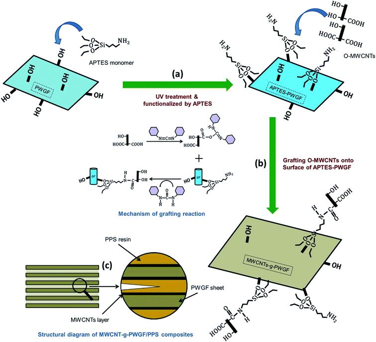 | ||
| Fig. 1 Schematics of (a and b) pathway for preparation of MWCNTs grafted PWGF sheets; and (c) the structural diagram of MWCNTs-g-PWGF/PPS composites. | ||
3.1. Modifying PWGF by APTES
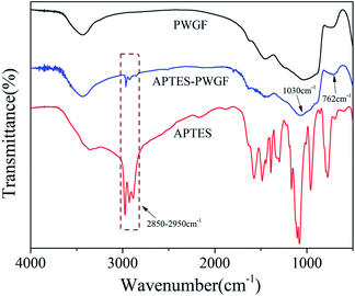
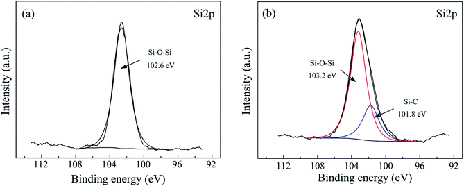
At the interface between the glass fiber and the silane coupling agent, the hydroxyl groups of the silanes and those of the glass fiber surface can react with each other through siloxane bonding or hydrogen bonding.41 The FTIR spectra of PWGF, APTES and APTES-PWGF were shown in Fig. 2. The peaks at 762 and 1030 cm−1 on the spectrum of APTES-PWGF were attributed to the vibration of Si–O–Si bond, while the band in the region of 2950–2850 cm−1 of the APTES could be attributed to the stretching vibration of C–H in methylene groups of APTES. In addition, C–H peaks were also observed in the spectrum of APTES-PWGF, but which did not appear in the FTIR spectrum of PWGF, indicating the possibility that APTES were chemically linked onto PWGF.Additionally, XPS analysis was performed to confirm the surface modification of the PWGF using APTES as shown in Fig. 3. The Si 2p peak around 102.6 eV was attributed to Si–O–Si, which is in agreement with Barr and Seal.42 After grafting, a new peak belonged to Si–C appeared at 101.8 eV, which supporting the conclusion that the APTES groups have been chemically grafted onto the PWGF surface.
3.2. Oxidation of MWCNTs
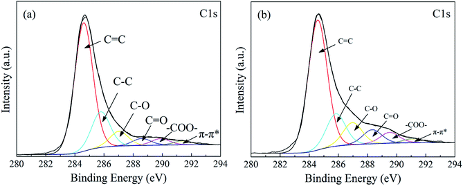
In order to evaluate the oxidization process of MWCNTs quantitatively, MWCNTs and O-MWCNTs samples were characterized by XPS as shown in Fig. 4. These C 1s peaks located at 284.6 eV, 285.8 eV, 287.0 eV, 288.6 eV, 289.9 eV and 291.4 eV, were corresponded to C![[double bond, length as m-dash]](https://www.rsc.org/images/entities/char_e001.gif) C (sp2), C–C (sp3), C–O, C
C (sp2), C–C (sp3), C–O, C![[double bond, length as m-dash]](https://www.rsc.org/images/entities/char_e001.gif) O, –COO– and π–π* transitions, respectively.43 The content of the carbon element in different chemical environments for MWCNTs and O-MWCNTs were listed in Table 1. After oxidation, the contents of C–O, C
O, –COO– and π–π* transitions, respectively.43 The content of the carbon element in different chemical environments for MWCNTs and O-MWCNTs were listed in Table 1. After oxidation, the contents of C–O, C![[double bond, length as m-dash]](https://www.rsc.org/images/entities/char_e001.gif) O and –COO– groups increased from 7.49 at%, 3.53 at% and 3.31 at% for MWCNTs sample to 10.36 at%, 6.59 at% and 5.04 at% for O-MWCNTs sample respectively, suggesting the surface oxygen-containing groups of O-MWCNTs were increased significantly. In the view of these results, one could conclude that MWCNTs was oxidized successfully.
O and –COO– groups increased from 7.49 at%, 3.53 at% and 3.31 at% for MWCNTs sample to 10.36 at%, 6.59 at% and 5.04 at% for O-MWCNTs sample respectively, suggesting the surface oxygen-containing groups of O-MWCNTs were increased significantly. In the view of these results, one could conclude that MWCNTs was oxidized successfully.
| Type | Content (at%) | Binding energy (eV) | |
|---|---|---|---|
| MWCNT | O-MWCNT | ||
C![[double bond, length as m-dash]](https://www.rsc.org/images/entities/char_e001.gif) C (sp2) C (sp2) |
65.42 | 60.81 | 284.6 |
| C–C (sp3) | 18.22 | 15.81 | 285.8 |
| C–O | 7.49 | 10.36 | 287.0 |
C![[double bond, length as m-dash]](https://www.rsc.org/images/entities/char_e001.gif) O O |
3.53 | 6.59 | 288.3 |
| –COO– | 3.31 | 5.04 | 289.5 |
| π–π* transitions | 2.03 | 2.00 | 291.1 |
3.3. Surface characteristics of MWCNTs grafted PWGF
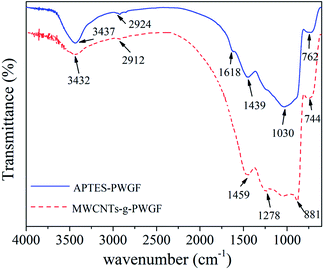
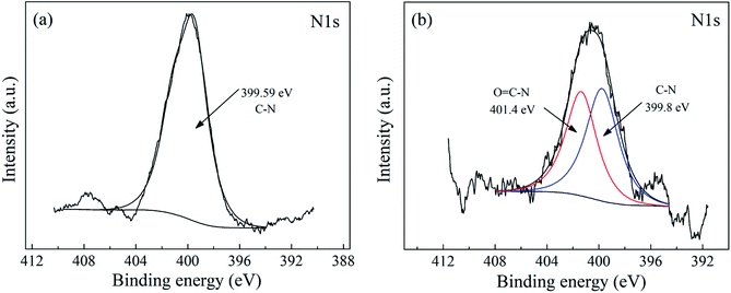
To confirm whether MWCNTs were grafted onto PWGF successfully, the FTIR spectra of APTES-PWGF and MWCNTs-g-PWGF were measured as shown in Fig. 5. The peaks at 762 and 1030 cm−1 for the stretching vibrations of Si–O–Si bonds shifted to 744 and 881 cm−1 which might be caused by the changes of chemical interaction between MWCNTs and APTES. The peak at 3437 cm−1 which was assigned to the –OH group on the APTES shifted to 3432 cm−1 after grafting the MWCNTs. This shift could be attributed to the changing of chemical environment and proved that MWCNTs were chemically linked on PWGF. In addition, the strong peak of C–N stretching vibration of primary amine group at 1439 cm−1 transformed to a weak peak at 1278 cm−1. This result indicated that the amide groups were formed by reaction between the primary amino groups of APTES and the carboxyl group of MWCNTs.44 Meanwhile, the peak at 1618 cm−1 assigned to N–H wagging vibration transformed into a strong peak at 1459 cm−1 as seen in the spectrum after grafting. This result also proved the possible reactions showing in Fig. 2(b).XPS was employed to illustrate the truth of chemical linkage between MWCNTs and PWGF. As shown in Fig. 6(a), the peak at 399.6 eV was related to C–N group of APTES, which meant that the nitrogen atoms were in a single chemical environment. In contrast, the binding energy of N 1s at 399.8 eV and 401.4 eV were corresponded to C–N and O![[double bond, length as m-dash]](https://www.rsc.org/images/entities/char_e001.gif) C–N group of MWCNTs-g-PWGF as shown in Fig. 6(b), suggesting the chemical environments for nitrogen atoms were changed after grafting.45 The component for the O
C–N group of MWCNTs-g-PWGF as shown in Fig. 6(b), suggesting the chemical environments for nitrogen atoms were changed after grafting.45 The component for the O![[double bond, length as m-dash]](https://www.rsc.org/images/entities/char_e001.gif) C–N group at 401.4 eV illustrated the presence of amide groups, which generated by amidation reaction between the MWCNTs and APTEs-PWGF. Thus, the results of XPS confirmed that the MWCNTs were grafted on PWGF chemically.
C–N group at 401.4 eV illustrated the presence of amide groups, which generated by amidation reaction between the MWCNTs and APTEs-PWGF. Thus, the results of XPS confirmed that the MWCNTs were grafted on PWGF chemically.
In order to understand the effect of modification of PWGF in detail, we investigated the content change of elements of C/N/O/Si in different samples. As we can see from Table 2, compared with APTES-PWGF and MWCNTs-g-PWGF, the contents of O and Si on the surface of PWGF are highest, while the C and N are lowest. After the treatment by APTES, the content of C and N on the surface of APTES-PWGF increased substantially, which the content of O and Si decreased significantly, which proved the surface of PWGF modified by APTES successfully. After further grafting of MWCNTs, the content of C increased slightly, but the content of N, O and Si also decreased moderately. According to the process of chemical reaction, the change of element content proved that each step of modifying and grafting reaction were successful.
| Samples | Content of elements (at%) | |||
|---|---|---|---|---|
| C | N | O | Si | |
| PWGF | 32.42 | 2.33 | 52.61 | 12.64 |
| APTES-PWGF | 60.55 | 6.57 | 26.81 | 6.07 |
| MWCNTs-g-PWGF | 62.43 | 6.42 | 26.21 | 4.94 |
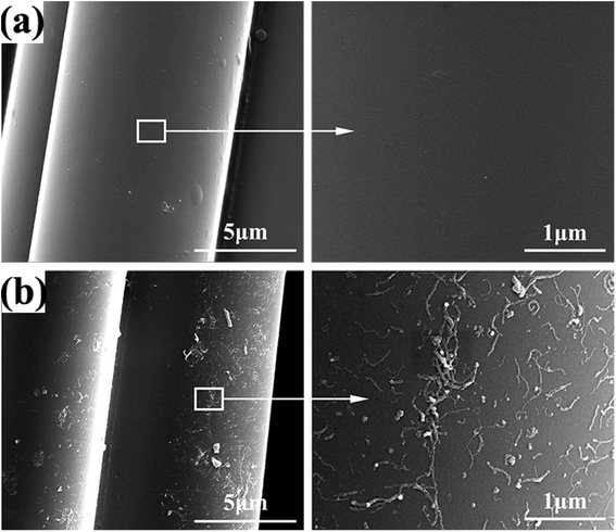
Furthermore, the dispersions of APTES and MWCNTs on the surface of glass fiber were investigated by SEM as shown in Fig. 7. Modifying of APTES did not alter significantly the appearance of the PWGF surface. Compared with APTES-PWGF, the grafted MWCNTs presented randomly dispersion on the surface but part of the MWCNTs also clumped together.
3.4. Interfacial properties of composite laminates
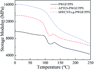
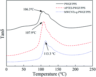
The strong interfacial interaction between PWGF sheets and PPS matrix was essential to improve the mechanical properties of composite laminates. In order to further illustrate the effect of APTES treatment as well as MWCNTs graft on the interfacial interaction, DMA was employed to investigate the storage modulus and glass transition temperature of composites with different treatment conditions of PWGF. The storage modulus can be used to characterize the information about the load bearing capacity of material and interfacial compatibility of composites. Higher storage modulus attributed to a higher rigidity of material, and the storage modulus is sensitive to the entanglement of resin molecules. As shown in Fig. 8, the storage modulus of PWGF/PPS, APTES-PWGF/PPS, MWCNTs-g-PWGF/PPS presents gradually rising trend, which indicated that the surface treatments of PWGF improved the interfacial adhesion of composites. More active groups such as amino and carboxyl groups were exposed to the surface of PWGF after APTES treatments, and these active groups generated interaction with PPS resin. As for MWCNTs-g-PWGF/PPS, the active groups on the surface of MWCNTs acted as cross-linking points with PPS resin, which gave rise to entanglements of PPS resin and increases the rigidity of molecular chains.The glass transition temperature (Tg) of PPS resin in the composite can be used to indicate the extent of entanglement of PPS chains. Furthermore, the degree of entanglement of molecular chains is closely related to the interfacial interaction. Stronger interaction force indicates more entanglement of molecular chains and results in a higher Tg. The tan![[thin space (1/6-em)]](https://www.rsc.org/images/entities/char_2009.gif) δ-temperature curves for the PWGF/PPS, APTES-PWGF/PPS, and MWCNTs-g-PWGF/PPS were shown in Fig. 9. The appearance of loss peak of DMA was caused by the movement of the PPS chain segment while the temperature was increasing. The more difficult the chain segment was to move, the higher temperature (or activation energy) was required for its movement. After grafting APTES and MWCNTs, the interfacial adhesion between PPS matrix and PWGF was enhanced, and the ability of movement of PPS chain segment was further inhibited by the PWGF, which induced that the Tg of the composite increased. Due to the difficulty of the chain segment motion corresponded to different temperature, the wide peak (temperature range) meant that there were varying PPS chain segments with different motion capabilities. The different could be interpreted as the different adhesion between PPS and PWGF: the adhesion in the point of interface defect or far from the fiber is weak. Therefore, the narrowing of the loss peak could also indicate that the defects at the interface of the composite material were reduced and the interfacial adhesion was enhanced after grafting.
δ-temperature curves for the PWGF/PPS, APTES-PWGF/PPS, and MWCNTs-g-PWGF/PPS were shown in Fig. 9. The appearance of loss peak of DMA was caused by the movement of the PPS chain segment while the temperature was increasing. The more difficult the chain segment was to move, the higher temperature (or activation energy) was required for its movement. After grafting APTES and MWCNTs, the interfacial adhesion between PPS matrix and PWGF was enhanced, and the ability of movement of PPS chain segment was further inhibited by the PWGF, which induced that the Tg of the composite increased. Due to the difficulty of the chain segment motion corresponded to different temperature, the wide peak (temperature range) meant that there were varying PPS chain segments with different motion capabilities. The different could be interpreted as the different adhesion between PPS and PWGF: the adhesion in the point of interface defect or far from the fiber is weak. Therefore, the narrowing of the loss peak could also indicate that the defects at the interface of the composite material were reduced and the interfacial adhesion was enhanced after grafting.
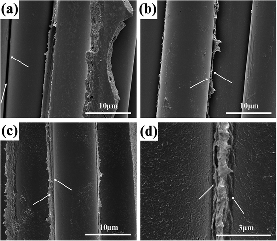
In order to further confirm the existence of the interactions between MWCNTs-g-PWGF and PPS matrix, SEM was applied to observe the interlamination surface of CNTs-g-PWGF/PPS composites after separated in single layers. As shown in Fig. 10, the arrows indicated the crevice between PWGF and PPS. The detachment of phases was shown obviously in PWGF/PPS (a) and the surface of PWGF was smooth with no PPS resin adhered, which meant poor interfacial compatibility and low interfacial interaction. After APTES treatment, although cracks can be seen in APTES-PWGF/PPS (b), PPS resin was attached on PWGF which improve the interfacial properties. As for MWCNTs-g-PWGF/PPS (c and d), PWGF and PPS were joined tightly with none gaps, evincing good compatibility and strong interfacial interactions. It was because that the MWCNTs improve the contact area and compatibility between reinforcements and matrix. Besides, the strong interfacial interactions could be achieved by the functional groups between the oxidizing groups on MWCNTs and PPS chains.
3.5. Mechanical properties
The strength and Young's modulus of the three different composites were given in Fig. 11. Compared with PWGF/PPS, APTES-PWGF/PPS and MWCNTs-g-PWGF/PPS displayed a higher value in tensile strength, bending strength, tensile modulus, and bending modulus. A remarkable increase was attributed to the enhancement of interfacial interaction between reinforced fibers and PPS matrix. For example, with APTES treatment, the tensile strength increased by 54% from 115 MPa to 178 MPa, while the bending strength raised by 27% from 67 MPa to 85 MPa. Besides, after MWCNTs grafted, the tensile strength increased by 127% from 115 MPa to 261 MPa whereas the bending strength improved by 155% from 67 MPa to 171 MPa. Therefore, the APTES treatment and MWCNTs grafting resulted in enormous improvements in mechanical properties.The obvious improvement in the mechanical properties of MWCNTs-g-PWGF/PPS composites can be attributed to several factors: (a) better compatibility between MWCNTs-g-PWGF and PPS matrix, which resulted in more effective mechanical load transfer from the matrix to the reinforcement; (b) bigger specific surface area of PWGF after grafting, which provided more load transfer area between fiber surface and matrix; (c) fewer interface defects, which reduced the crack caused by stress concentration during loading process. As shown in Fig. 12, the grafted MWCNTs on the surface of PWGF were pierced into PPS matrix, which provided a firm path to improve the efficiency of load transfer from PPS matrix to PWGF.
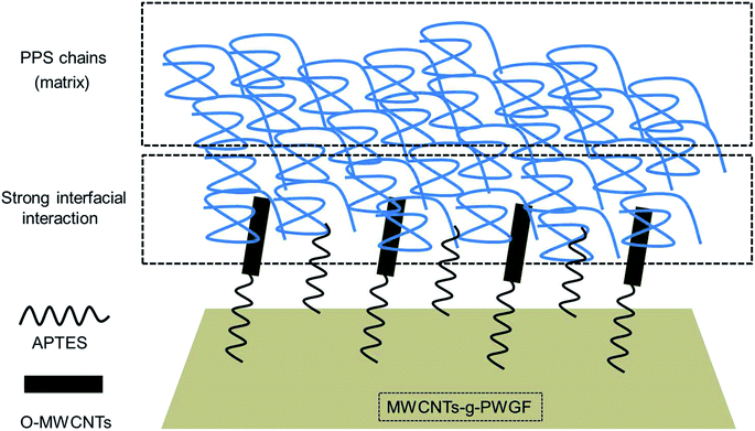 | ||
| Fig. 12 Schematic illustration of microstructure of the interface between PPS matrix and MWCNTs-g-PWGF. | ||
4. Conclusions
In conclusion, the MWCNTs-g-PWGF/PPS composites with a well-distributed dispersion of MWCNTs were prepared successfully via novel chemical modification method and hot-pressing process. According to the results, the MWCNTs-g-PWGF not only showed good adhesion between MWCNTs and PWGF, but also formed strong interfacial interactions with the PPS chain of the matrix. MWCNTs just like ‘anchors’ which were inserted in the matrix, and these ‘anchors’ enhance the contact area between the glass fiber and PPS matrix. On account of these remarkable structures, a significant improvement on the mechanical properties of MWCNTs-g-PWGF/PPS composite was obtained due to effective load transfer from PPS matrix to MWCNTs-g-PWGF. Furthermore, the Tg of MWCNTs-g-PWGF/PPS composites showed to be higher than that of PWGF/PPS composites. Consequently, oxidation of MWCNTs with chemical grafting modification to prepare MWCNTs-g-PWGF/PPS composites provided a novel and concise method to develop glass fiber reinforced PPS composites with excellent interfacial interaction and showed a further potential for improvement of the composite performance.Conflicts of interest
There are no conflicts to declare.Acknowledgements
The authors are grateful to the National Key R&D Program of China for financial support (Project No. 2016YFB1200602).References
- Y. Yonggang, L. Yubao, Y. Zheng, Z. Yi, W. Jie, C. Xia and C. Yongrong, Eur. Polym. J., 2003, 39, 411–416 CrossRef.
- L. Caramaro, B. Chabert, J. Chauchard and T. Vu-Khanh, Polym. Eng. Sci., 1991, 31, 1279–1285 CrossRef CAS.
- K. Zhang, G. Zhang, B. Liu, X. Wang, S. Long and J. Yang, Compos. Sci. Technol., 2014, 98, 57–63 CrossRef CAS.
- H. Li, G. y. Lv, G. Zhang, H. h. Ren, X. x. Fan and Y. g. Yan, Polym. Int., 2014, 63, 1707–1714 CrossRef CAS.
- N. Zwettler, J. S. Engbæk, R. Lundsgaard, I. Paranowska, T. E. Nielsen, S. Clyens, J. Christiansen and M. Ø. Andersen, React. Funct. Polym., 2015, 88, 47–54 CrossRef CAS.
- A. M. Díez-Pascual and A. L. Díez-Vicente, ACS Appl. Mater. Interfaces, 2014, 6, 10132–10145 CrossRef.
- H. W. Hill Jr and D. Brady, Polym. Eng. Sci., 1976, 16, 831–835 CrossRef.
- J. Z. Liang, Polym. Int., 2012, 61, 511–515 CrossRef CAS.
- Z. Jiang, L. A. Gyurova, A. K. Schlarb, K. Friedrich and Z. Zhang, Compos. Sci. Technol., 2008, 68, 734–742 CrossRef CAS.
- Y. F. Zhao, M. Xiao, S. J. Wang, X. C. Ge and Y. Z. Meng, Compos. Sci. Technol., 2007, 67, 2528–2534 CrossRef CAS.
- B. Liu, Z. Liu, X. Wang, G. Zhang, S. Long and J. Yang, Polym. Test., 2013, 32, 724–730 CrossRef CAS.
- S. C. Tjong, S. A. Xu, K. Y. Li and Y. W. Mai, Compos. Sci. Technol., 2002, 62, 2017–2027 CrossRef CAS.
- M. R. Kamal, A. T. Mutel and L. A. Utracki, Polym. Compos., 1984, 5, 289–298 CrossRef CAS.
- C. Kaynak, O. Orgun and T. Tincer, Polym. Test., 2005, 24, 455–462 CrossRef CAS.
- L. Ibarra and D. Paños, J. Appl. Polym. Sci., 2015, 67, 1819–1826 CrossRef.
- A. Arici, J. Compos. Mater., 2005, 39, 21–33 CrossRef CAS.
- M. Nikforooz, J. Montesano, M. Golzar and M. M. Shokrieh, Polym. Test., 2018, 67, 457–467 CrossRef CAS.
- S. J. Park and J. S. Jin, J. Colloid Interface Sci., 2001, 242, 174–179 CrossRef CAS.
- F. Sliwa, E. Bounia, F. Charrier, G. Marin and F. Malet, Compos. Sci. Technol., 2012, 72, 1733–1740 CrossRef CAS.
- L. H. Peng, L. C. Xiang, L. Y. Hong, Y. Yu, L. K. Xi and H. E. Fu, New Carbon Mater., 2005, 20, 39–44 Search PubMed.
- E. Jeong, J. Kim, S. H. Cho, J. I. Kim, I. S. Han and Y. S. Lee, J. Ind. Eng. Chem., 2011, 17, 191–197 CrossRef CAS.
- L. Y. Yuan, S. S. Shyu and J. Y. Lai, Compos. Sci. Technol., 1992, 45, 9–16 CrossRef CAS.
- X. L. Fu, C. Ddl and W. M. Lu, Carbon, 1998, 36, 1337–1345 CrossRef CAS.
- N. Shahid, R. G. Villate and A. R. Barron, Compos. Sci. Technol., 2005, 65, 2250–2258 CrossRef CAS.
- K. T. Lau and D. Hui, Composites, Part B, 2002, 33, 263–277 CrossRef.
- D. Qian, G. J. Wagner, W. K. Liu, M.-F. Yu and R. S. Ruoff, Appl. Mech. Rev., 2002, 55, 495–533 CrossRef.
- J. P. Salvetat-Delmotte and A. Rubio, Carbon, 2002, 40, 1729–1734 CrossRef CAS.
- E. W. Wong, P. E. Sheehan and C. M. Lieber, Science, 1997, 277, 1971–1975 CrossRef CAS.
- M. F. Yu, J. Eng. Mater. Technol., 2004, 126, 271–278 CrossRef CAS.
- E. Bekyarova, E. T. Thostenson, A. Yu, H. Kim, J. Gao, J. Tang, H. T. Hahn, T. W. Chou, A. M. E. Itkis and R. C. Haddon, Langmuir, 2007, 23, 3970 CrossRef CAS.
- A. Laachachi, A. Vivet, G. Nouet, B. B. Doudou, C. Poilâne, J. Chen, J. B. Bai and M. H. Ayachi, Mater. Lett., 2008, 62, 394–397 CrossRef CAS.
- Q. Peng, X. He, Y. Li, C. Wang, R. Wang, P. A. Hu, Y. Yan and T. Sritharan, J. Mater. Chem., 2012, 22, 5928–5931 RSC.
- E. T. Thostenson and T.-W. Chou, J. Phys. D: Appl. Phys., 2003, 36, 573 CrossRef CAS.
- J. Zhao, L. Liu, Q. Guo, J. Shi, G. Zhai, J. Song and Z. Liu, Carbon, 2008, 46, 380–383 CrossRef CAS.
- A. Warrier, A. Godara, O. Rochez, L. Mezzo, F. Luizi, L. Gorbatikh, S. V. Lomov, A. W. VanVuure and I. Verpoest, Composites, Part A, 2010, 41, 532–538 CrossRef.
- J. Zhang, R. Zhuang, J. Liu, E. Mäder, G. Heinrich and S. Gao, Carbon, 2010, 48, 2273–2281 CrossRef CAS.
- S. Zhang, B. W. Liu, F. L. Hao, C. W. Jiao and F. Yang, Compos. Sci. Technol., 2013, 88, 120–125 CrossRef CAS.
- A. Feng, C. Lu and H. Lu, J. Mater. Sci., 2012, 47, 3327–3333 CrossRef.
- J. Sheng, Y. Wu, X. Yang and J. Zhang, Int. J. Hydrogen Energy, 2009, 34, 1123–1125 CrossRef CAS.
- W. S. Hummers Jr and R. E. Offeman, J. Am. Chem. Soc., 1958, 80, 1339 CrossRef.
- J. Jang and H. S. Kim, J. Appl. Polym. Sci., 1996, 60, 2297–2306 CrossRef CAS.
- T. L. Barr, S. Seal, H. He and J. Klinowski, Vacuum, 1995, 46, 1391–1395 CrossRef CAS.
- Y. C. Chiang, W.-H. Lin and Y.-C. Chang, Appl. Surf. Sci., 2011, 257, 2401–2410 CrossRef CAS.
- C. Weigel and R. Kellner, Fresenius' Z. für Anal. Chem., 1989, 335, 663–668 CrossRef CAS.
- N. Arnaiz, I. Martin-Gullon, R. Font and M. F. Gomez-Rico, J. Anal. Appl. Pyrolysis, 2018, 130, 52–61 CrossRef CAS.
| This journal is © The Royal Society of Chemistry 2019 |

