
 Open Access Article
 This Open Access Article is licensed under a Creative Commons Attribution-Non Commercial 3.0 Unported Licence
Molecular orientation and stability of poly(3-hexylthiophene) nanogratings affected by the fabricated solvent vapor†
Menxiang Qianab,
Zhanhua Songab,
Guangzhu Ding *ab,
Zhijun Huc and
Jieping Liuab
*ab,
Zhijun Huc and
Jieping Liuab
aCollege of Chemistry and Materials Science, Huaibei Normal University, Huaibei 235000, China. E-mail: dinggz@chnu.edu.cn
bAnhui Key Laboratory of Energetic Materials, Anhui 235000, China
cCenter for Soft Condensed Matter Physics and Interdisciplinary Research, Soochow University, Suzhou, 215123, China
First published on 11th September 2019
Abstract
During the nanoimprinting lithography (NIL) process, the role of solvent vapor in fabricating the pattern structure and inducing the molecular alignment of nanoimprinted polymer film has been attracting significant attention. We demonstrate here that the molecular orientation and thermal stability of poly(3-hexylthiophene) (P3HT) nanograting film can be affected obviously by the fabricated solvent vapor. A solvent-vapor nanoimprinting lithography (SV-NIL) technique based on a polydimethylsiloxane (PDMS) template is employed to fabricate a P3HT nanograting structure film successfully and solvent vapor is offered by chlorobenzene, chloroform and carbon disulphide, respectively. The molecular orientation of the polymer film is carefully characterized by grazing incidence wide angle X-ray diffraction (GIWAXD) measurements to investigate the effect of various solvent vapors on the molecular orientation of the P3HT nanograting film. For the P3HT nanograting film fabricated by chloroform and chlorobenzene solvent, the edge-on molecular orientation of the typical form II crystallographic structure is induced. However, this indicates that there are both the face-on molecular orientations of the form II and form I crystallographic conformation present for the P3HT nanograting film fabricated by carbon disulphide solvent. Therefore, the fabricated solvent vapor plays a significant role in determining the formation of the molecular orientation of the polymer nanostructure. Then, the role of thermal annealing in the stability of the molecular orientation was investigated for the P3HT nanograting film after a fixed temperature. As for the annealed nanograting film fabricated by chlorobenzene and chloroform solvent vapor, a single edge-on molecular orientation mode of the form I crystallographic structure has been obtained. However, for the annealed nanograting film fabricated by the carbon disulphide solvent, the edge-on and face-on molecular orientations of the form I crystallographic structure are still retained. This indicates that the stability of the form II crystallographic conformation is mainly dependent on the thermal annealing process. Therefore, after the annealing process, the final determining of the molecular alignment and crystallographic conformation depends significantly on the orientation type of the nanograting film before the annealing history, and it can be further inferred that the molecular orientation of the annealed polymer film is still affected by the fabricated solvent vapor significantly. Thus this will provide new understanding and guidance for the research of the topographical structure and molecular alignment of conjugated polymers.
Introduction
With the development of nanometer science and technique, the configuration of organic optoelectronic devices from the micro to the nanometer scale is able to improve device performance or optoelectronic material function. Therefore, the future improvement of optoelectronic techniques strongly demands the structure fabrication of the nanometer scale or even smaller sizes for photoelectric material applications. Fortunately, many microlithography and nanolithography techniques have been proposed and enhanced continuously for the fabrication of smaller or denser integrated circuits, such as plasmonic lithography,1,2 extreme-UV lithography,3 electron-beam lithography,4,5 nanoimprinting,6,7 dip-pen lithography8,9 and so on.Nanoimprinting lithography (NIL) was proposed for the first time in the 1990s by Chou.6,10 Since then, this fabrication method has been proven to pattern feature structures of different dimensions from nanometers to micrometers successfully for the past tens of years.7,11–21 NIL is investigated as the most promising and has unique advantages such as high resolution, high throughput, low cost, compatibility with various materials, and fast processing speed. During the classical NIL process,6,10 a hard template is employed to deform the thermal plastic polymer under heating and pressure, in order to produce a reverse replica of the template pattern on the polymer film surface. Compared to a hard template, a soft template is usually lower cost, has better contact with the substrate surface, is easier to crush and it is easier to de-mold, such as the polydimethylsiloxane (PDMS) template.21 The PDMS template, as a mould for NIL, is elastomeric and is able to have complete conformal contact with a substrate bearing an even or curved substrate surface.22–27 Michel22 reported the formulation of siloxane polymers with high-resolution and high-accuracy as templates for soft lithography. To better formulate template polymers, they used models of rubber-like elasticity as guidelines and fabricated PDMS networks from vinyl and hydrosilane end-linked polymers and vinyl and hydrosilane copolymers, considering the mass between cross-links and junction functionality. Whitesides24 demonstrated that by using easily fabricated and composite PDMS masks in phase-shifting lithography it was possible to fabricate arrays of rings in a photoresist with dimensions as small as 30 nm. Paul et al. employed a PDMS stamp as an elastomeric mask to fabricate a patterned nanostructure on a curved surface and the feature size of the pattern could be improved into 175 nm.26 Han's group found that, as a PDMS template was exposed to a solvent vapor, it would be swollen by the solvent and thus became a solvent container during the whole pattern process.28 Finally, the solvent within the PDMS template diffused into the polymer material and improved polymer molecule mobility to form the pattern structure of the polymer film. As a matter of fact, when solvent vapor was chosen appropriately during the pattern fabrication process, it was demonstrated that solvent vapor was not only able to assist the success of pattern fabrication of polymer film but also to induce the formation of the preferential molecular and crystallographic alignment of the imprinted polymer material.29–31 Therefore, during the NIL process, the role of solvent vapor in inducing the molecular alignment of the nanoimprinted polymer film has attracted significant attention. Han et al.29 found that a poly(3-hexylthiophene) (P3HT) polymer film bearing a hierarchical ordered structure was fabricated by a vapor-assisted imprinting method with a combination interaction with a carbon disulphide (CS2) and thermal annealing, and it indicated that the chains in the P3HT domains displayed a flat-on conformation within the hierarchical ordered structure due to the enhanced intermolecular interaction of the alkyl side chains in CS2 vapor. Jung's research30 indicated that a patterned P3HT:PCBM mixture film can be prepared by thermal and solvent-assisted soft NIL based on the flexible PDMS molds under various patterning conditions. According to further analysis of grazing incident X-ray diffraction (GIXRD), it showed that the uniform vertical or face-on compositional distribution and conformation had been induced or enhanced for the patterned polymer mixture during the solvent-assisted soft nanoimprint lithography process. In addition, this preferential orientation or distribution had a significant effect on the performance of photovoltaic cells. In our previous work,31 we also used the vapor-assisted room-temperature NIL (VART-NIL) method to fabricate P3HT nanograting polymer film and the results indicated that a preferential face-on chain alignment of the π–π stacking of P3HT chains was induced by the solvent vapor interaction.
As reported, for the unpatterned polymer film, it was indicated that selected solvent vapor treatment demonstrated great potential to be further improved to control the preferential morphology and molecular alignment of the semiconducting conjugated polymer film, which was beneficial for the desired channel to serve as the transportation pathways of charge carriers for the actual requirement.32–37 Yang32 indicated that a solvent-vapor annealing method was employed to induce the alignment transformation of a regioregular P3BT polymer film. This showed that short alkyl-substituted polythiophene P3BT behaved with an unusual form modification and a perpendicular alignment with respect to the substrate was present at the rigid polythiophene backbones within the polymer film after the solvent-vapor treatment. This result could be the enhanced charge-carrier mobility in the direction normal to the film surface. Therefore, for the patterned polymer film, it is significant to obtain a comprehensive understanding of solvent vapor interaction in determining the molecular alignment of the semiconducting polymer, especially for the solvent vapor nanoimprinting process.
In this paper, we used the solvent-vapor nanoimprinting lithography (SV-NIL) technique to fabricate a nanograting structure on the surface of a P3HT thin film. A PDMS template was chosen as the NIL mold and the solvent was offered by chlorobenzene, chloroform and carbon disulphide, respectively. The molecular orientation of the polymer film was carefully characterized by grazing incidence wide angle X-ray diffraction (GIWAXD) coupled with area detectors. The effect of the various solvent vapors on the morphology and molecular orientation of the P3HT nanograting film was investigated in detail. Then, the thermal stability of the molecular orientation determined by various solvent vapors was also investigated for the P3HT nanograting film after a thermal annealing process. A detailed connection between molecular orientation and thermal annealing was concluded carefully.
Experimental
The conjugated polymer P3HT used in this paper (Mw 50![[thin space (1/6-em)]](https://www.rsc.org/images/entities/char_2009.gif) 000 g mol−1) was purchased from Rieke Metals Inc. and was applied as received.
000 g mol−1) was purchased from Rieke Metals Inc. and was applied as received.
Chlorobenzene was chosen as the solvent. A P3HT solution was prepared at room temperature to a concentration of 20 mg ml−1 and then it was filtered by the assistance of polytetrafluoroethylene filters (0.25 μm). A silicon sheet was chosen as the substrate to sustain the polymer film. It was washed completely with deionized water, ethanol, acetone and isopropyl alcohol several times and then it was dried on a hot plate. First, the P3HT solution was spun cast onto the surface of the silicon sheet substrate to fabricate the polymer film. The spin casting was carried out at a fixed spinning speed (1600 rpm) for 60 s. Then, the polymer film was enclosed in a vacuum pumping box to remove the residual solvent.
A P3HT nanograting polymer film was fabricated by the employment of a SV-NIL technique based on the poly(dimethylsiloxane) (PDMS) template. The unpatterned polymer film prepared as above was loaded into a closed chamber. The patterned structure was fabricated on the surface of the PDMS template in advance. First, the unpatterned P3HT film was covered with a PDMS template face to face and solvent was injected into the bottom of the closed chamber. The solvent would then evaporate to offer the solvent vapor for the NIL process and the solvent was offered by chlorobenzene, chloroform and carbon disulphide, respectively. Second, the SV-NIL process was carried out for 72 h in the conditions of fixed pressure (0.4 bar) and temperature (23 °C). Third, the closed chamber was opened for 24 h to evaporate the remaining solvent vapor in order to solidify the nanograting structure. Finally, the PDMS template was lifted off the P3HT polymer surface and therefore the patterned nanograting structure on the surface of P3HT film was obtained successfully. Then, the whole P3HT nanograting film was kept in the vacuum box for about 24 h to remove the residual solvent and was reserved for use.
The surface morphology of the samples was characterized using scanning electron microscopy (SEM) and atomic force microscopy (AFM). SEM measurement was carried out by Hitachi S-4800 equipment operated at 15 kV voltages. The investigation lens of the SEM investigation is performed to scan the thin film surface from the orthogonal or perpendicular position of the thin film surface and the obtained SEM image is called the top-down SEM image. AFM measurement was performed on Bruker equipment (Multimode 8) using the tapping mode. The X-ray diffraction data were obtained at beamline BL14B1 of the Shanghai Synchrotron Radiation Facility (SSRF) using X-rays with a wavelength of 1.2398 Å. Detailed information about beamline BL14B1 has been reported in previous literature.38 The incident angle of the X-ray beam was 0.18° during the GIWAXD measurement process. Data conversion to q space was obtained by calibration using LaB6 powder. The mediate beam stop was used to block the primary beam line for the two dimensional scanning of polymer film.
Results and discussion
Fig. 1 indicates the schematic fabrication process of the P3HT nanograting film according to the SV-NIL technique. The SV-NIL technique based on the PDMS template here is employed to fabricate the P3HT nanograting structure on the surface of P3HT thin film. The whole fabrication process based on the SV-NIL technique mainly consists of three steps. First, unpatterned P3HT film is prepared by spin coating from solution onto the surface of the silicon sheet. Second, the unpatterned polymer film is loaded into a closed vapor box and a SV-NIL process is carried out under the fixed vapor atmosphere and at room temperature. The PDMS template is allowed to adhere onto the unpatterned polymer film surface face to face and finally the nanoimprinted polymer film system is constructed from the substrate, polymer film and PDMS template and is formed into the structure of a sandwich. Third, after a sustained period of time, the PDMS template is lifted off the polymer surface and a patterned P3HT nanograting film is gained painstakingly on the surface of the silicon substrate.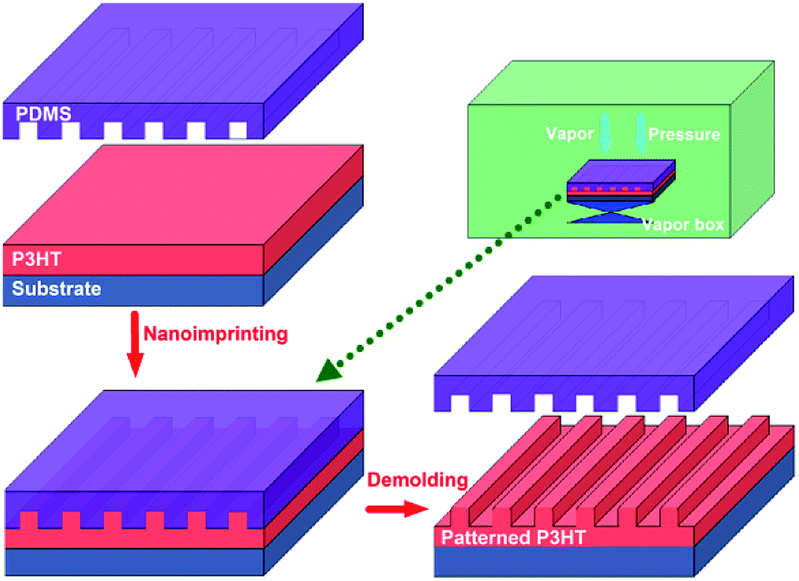 | ||
| Fig. 1 The schematic fabrication process of the P3HT nanograting film according to the SV-NIL technique. | ||
During the SV-NIL process, solvent is injected into the bottom of the closed box and it will evaporate to offer the solvent vapor for the NIL process. Then, the SV-NIL process is needed to be carried out for a sustained period of time under the combined action of fixed pressure and the solvent vapor in order to solidify the nanograting structure successfully. In order to fabricate the stable nanograting film structure, it is necessary to remove completely the residual solvent under a vacuum pumping system. The whole SV-NIL process is performed at room temperature and it can avoid the effect of high temperature on the properties of the polymer film. The PDMS template has complete conformal contact with the film surface and it is very convenient to lift off from the polymer film surface. In addition, the solvent vapor molecule can be absorbed into the PDMS template, then it further diffuses into the polymer molecule between the surface of polymer and the template and the polymer molecule will swell step by step to fulfill the cavity of the PDMS template. Thus, the fabrication process of the polymer pattern film based on the NIL technique is developed under solvent vapor and thus is noted as the SV-NIL method. This typical PDMS template can be reused repeatedly again to develop the nanograting film excellently and so it is simple and cost-effective to produce the nanostructure polymer film for the SV-NIL method.
Fig. 2 indicates the top-down SEM images of the PDMS template and the fabricated P3HT nanograting film. The fabricated P3HT nanostructures are very uniform over a large area. It clearly indicates the surface images of the PDMS template and the patterned P3HT nanograting film with identical line width at the same period (distance between the adjacent nanograting). The PDMS template consists of a structure of a line array bearing a ∼275 nm wide trench and a ∼550 nm period, while the patterned P3HT nanograting film has a ∼275 nm line width and a period of ∼550 nm. It can be inferred that both the line width and the period of the nanograting film match the dimensions of the PDMS template. The successful fabrication of the replication protocol is also indicated from the AFM height profiles. Fig. 3 shows the AFM height images of the PDMS template and the fabricated P3HT nanograting film. A further detailed indication of the same topography profile is examined from the corresponding cross-sectional images of the ESI shown in Fig. S1.† As we can see, a regular and periodic topography profile is shown both for the surface of the PDMS template and the P3HT nanograting film. The fabricated P3HT nanostructures are very uniform over a large area and there are no collapses or distortions on the surface of the P3HT nanograting film. The structure height of the P3HT nanograting film is about 75 nm, the same as that of the trenches in the PDMS template. This means that the polymer can merge into the trenches of the PDMS template and fill the grooves under the solvent vapor at room temperature. Therefore, it is illustrated that the SV-NIL technique can be used successfully to fabricate a nanograting structure on the surface of P3HT thin film with high replication fidelity.
 | ||
| Fig. 2 Top-down SEM images of the PDMS template (a) and the fabricated P3HT nanograting film (b). | ||
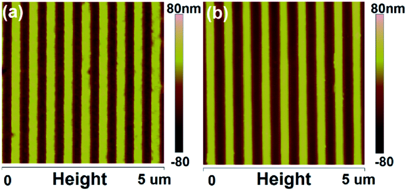 | ||
| Fig. 3 AFM height images of the PDMS template (a) and the fabricated P3HT nanograting film (b). | ||
Recent reports have suggested that the NIL method is not only able to fabricate a nanostructure profile but is also able to induce the transition of the molecular or crystallographic orientation of the fabricated nanostructure materials.29–31 Now, we turn our attention to focus on the investigation of the molecular orientation of the P3HT nanograting film fabricated by SV-NIL technique. Fig. 4 indicates the 2D GIWAXD profiles of the P3HT film for untreated film and the nanograting film with a nanograting line direction parallel or vertical to the direction of the incident X-rays. The parallel or vertical investigation is carried out in order to discuss the molecular alignment of the polymer molecule confined within nanograting comprehensively. A two-dimensional charge-coupled device detector is employed to receive the diffraction signal. Here it is noted that the (h00) plane, (010) plane and (001) plane are defined as the layering direction, π–π direction and backbone direction, respectively, according to the standard crystallographic notation of the P3HT polymer molecule.18,20,31,32 Diffraction vectors qxy and qz are noted as the diffraction signal examined from the in-plane and out-of-plane GIWAXD measurements (that is parallel and vertical to the substrate surface). For the P3HT polymer film, diffraction vector positions at about q = 3.8 nm−1 and q = 16.8 nm−1 are referred to as the reflection signals of the (100) plane and (010) plane, respectively.31,32
 | ||
| Fig. 4 Two-dimensional (2D) GIWAXD profiles of P3HT film for: (a) untreated film; (b) nanograting film with a nanograting line direction parallel to the direction of the incident X-rays (denoted as “Parallel”); and (c) nanograting film with a nanograting line direction vertical to the direction of the incident X-rays (denoted as “Vertical”). The solvent vapor is offered by chlorobenzene to fabricate the nanograting film. | ||
In addition, to better discuss the diffraction information of the P3HT polymer film in detail, one dimensional (1D) GIWAXD intensity images of the untreated film and nanograting film integrated along the qz direction and the qxy direction are also investigated, as shown in Fig. S2 of the ESI.† The corresponding data are integrated from the 2D images indicated in Fig. 4. As for the untreated P3HT film, there are only (h00) reflection peaks along the qz direction and (010) reflection peak appearing in the qxy direction simultaneously. Thus, it can be inferred that a single edge-on molecular orientation is present for the untreated P3HT film, in agreement with the previous results.31,32 Here it is noted that, the diffraction vector positions at about q = 3.8 nm−1, q = 7.6 nm−1, q = 11.4 nm−1 and q = 16.8 nm−1 are referred to as the reflection signals of the corresponding (100) plane, (200) plane, (300) plane and (010) plane of the typical form I crystallographic structure, respectively. As shown in Fig. S3 of the ESI,† it shows a schematic indication of a typical edge-on molecule orientation for P3HT molecule chains on the substrate surface. The lattice parameters a, b and c indicate the distance between backbones, the π–π stacking distance and the distance between side chains, respectively. However, an obvious difference of diffraction information can be obtained significantly for the diffraction profiles of the P3HT nanograting film. First of all, apart from the obvious (h00) diffraction peaks along the qz direction and (010) reflection peaks along the qxy direction, there is no other additional reflection signal for the diffraction profiles of the P3HT nanograting films. No other additional reflection signal indicates that no other new molecular orientation (for example, face-on molecular orientation) is induced for the P3HT nanograting film although performing a SV-NIL process. Secondly, as shown in Fig. S2,† it is indicated that there are obvious diffraction peaks (close to q = 5.2 nm−1 and q = 10.4 nm−1) both for the parallel and vertical reflection signals of the nanograting film. Compared to the diffraction peak of the untreated polymer film (q = 3.8 nm−1), the q value of the P3HT crystal is increased obviously. Similar investigation results have been reported previously.29,32,33 The change of q value mainly results from the crystallographic transition from form I to form II of the P3HT crystal and the diffraction peaks indicated at q = 5.2 nm−1 and q = 10.4 nm−1 are due to the (100) and (200) diffraction plane of the form II crystallographic structure. For the form II crystallographic structure, the increase of the diffraction q value means that the distance between alkyl chains is decreased slightly. Thus, it shows that the crystallographic structure can be induced from typical form I to form II for the P3HT nanograting film by exposing the polymer to the SV-NIL process. Thirdly, compared to the diffraction profile of the form I crystal, it is indicated that there are obvious additional diffraction peaks of the (h00) reflection signal of the form II crystal for the P3HT nanograting film along the qz direction, however, no evident transition of the diffraction peak position can be found along the qxy direction. It can be inferred that the π–π stacking distance, associated with the (010) plane reflection, cannot be induced to change or the change can be ignored for the form I and form II crystal crystallographic structures. Thus, it can be concluded here that the form II crystallographic structure has been guided to form for the P3HT nanograting film and there is only the transition of the distance between the alkyl chains between the form I and form II crystallographic structures, as shown in Fig. S3.† Then, it is noted that, although the diffraction profile of the P3HT nanograting film is investigated along the parallel and vertical directions in detail, the reflection signals are invariant for the P3HT nanograting film in the two directions. Thus it is concluded that the molecular chain orientation within the P3HT nanograting film is identical for the orthogonal directions of the polymer film.
Now, we turn our attention to the existence position within the P3HT nanograting film for the induced form II crystallographic structure. The form II crystallographic structure can be induced for the P3HT nanograting film by exposing the polymer to the SV-NIL process, however, it is uncertain where the induced form II crystallographic structure exists, is it within the nanograting line or in the residual layer beneath the nanograting pattern? Thus, the 1D GIWAXD intensity profiles of the untreated and unpatterned film are investigated in detail for the qz direction and qxy direction, as shown in Fig. S4 of the ESI.† The untreated polymer film is a pristine P3HT film as spin coated and without any treatment (as discussed above). The unpatterned film is obtained by the same conditions as the fabrication of the nanograting film (SV-NIL process) with an unpatterned PDMS film rather than a patterned PDMS template. This indicates that there are only the (h00) and (010) reflection profiles of the form I crystallographic structure appearing in the qz and qxy directions both for the untreated and unpatterned film. It can be inferred that single chlorobenzene vapor treatment cannot induce the formation of the form II crystallographic structure for the flat polymer film. As we known, there is a residual layer beneath the nanograting pattern of the P3HT nanograting film and the residual layer is a flat polymer film. Thus, it can be concluded naturally that the induced form II crystallographic structure of the P3HT molecule chains cannot be present at the residual layer beneath the nanograting pattern and it only exists in the nanograting line pattern of the P3HT nanograting film. Therefore, it is possible to ascertain that the confinement surrounding can contribute mainly to the formation of the form II crystal of the P3HT polymer molecules during the SV-NIL process rather than the simple effect of the solvent vapor.
Then, there is the problem of whether the fabricated solvent vapor during the SV-NIL process plays a significant role in determining the formation of the molecular orientation of the polymer nanostructure or not. In order to explain the effect, an investigation of the various solvent vapors during the SV-NIL process was carried out. Various solvent vapors for the NIL process are offered by chloroform and carbon disulphide to investigate the effect in detail. Here we chose to study the solvents of chlorobenzene, chloroform and carbon disulphide for two main reasons only. On the one hand, chlorobenzene, chloroform and carbon disulphide solvents are all able to dissolve the P3HT polymer and furthermore they are all used to perform the processing of conjugated polymers in nanometer science and applications extensively. Thus, it is significant to employ chlorobenzene, chloroform and carbon disulfide solvent vapor to fabricate the P3HT nanograting film and investigate the molecular orientation. On the other hand, here we want to know whether the fabricated solvent vapor during the SV-NIL process plays a significant role in determining the formation of the molecular orientation of the polymer nanostructure or not. Yet it is indicated that various molecule orientations can be induced for the P3HT nanograting film fabricated by different solvent vapors (chlorobenzene, chloroform and carbon disulphide) during the SV-NIL process. Thus, it is very suitable to choose chlorobenzene, chloroform and carbon disulphide solvent to explore the effect of solvent vapor on the pattern fabrication and molecular alignment.
Fig. 5 shows the AFM height images of the P3HT nanograting film by the SV-NIL process with chloroform solvent and carbon disulphide solvent. It can be seen that a regular and periodic topography profile is obtained successfully for the surface of the P3HT nanograting film both by chloroform solvent and carbon disulphide solvent. The nanostructure profiles of the P3HT nanograting film (both fabricated by two solvents) are also very uniform over a large area and there are also no collapses or distortions on the film surface. Thus, it is suggested that the P3HT nanograting film can be fabricated successfully by the SV-NIL technique with chlorobenzene, chloroform and carbon disulphide solvent.
 | ||
| Fig. 5 AFM height images of the P3HT nanograting film by the SV-NIL process with chloroform solvent (a) and carbon disulfide solvent (b). | ||
Fig. 6 indicates the 2D GIWAXD profiles of the P3HT nanograting film by the SV-NIL process with chloroform and carbon disulphide solvent. In order to discuss the diffraction signals in detail, 1D GIWAXD intensity profiles of the P3HT nanograting film are also investigated as shown in Fig. S5 of the ESI.† The integrated data are collected from the corresponding 2D images as shown in Fig. 6.
 | ||
| Fig. 6 2D GIWAXD profiles of P3HT nanograting film by SV-NIL process with chloroform solvent (a) and carbon disulfide solvent (b). | ||
For the P3HT nanograting film fabricated by chloroform solvent, it is shown that, apart from the obvious (h00) diffraction peaks along the qz direction and the (010) reflection peaks along the qxy direction, there are also no other additional reflection signals. For the investigation in detail, diffraction peaks (close to q = 3.8 nm−1, q = 7.6 nm−1 and q = 11.5 nm−1) can be obtained obviously for the reflection signal of the nanograting film along the qz direction, however, diffraction peaks (close to q = 5.2 nm−1 and q = 10.4 nm−1) can also be present at the reflection images of the nanograting film along the qz direction. No evident diffraction peak position can be investigated along the qxy direction except for the diffraction signal positioned at q = 16.8 nm−1. In a word, there are a similar reflection signal images surprisingly between the P3HT nanograting films fabricated by chlorobenzene and chloroform, for the qxy direction and qz direction. Thus, according to the above discussion, it can be inferred that an edge-on molecular orientation of the typical form I crystallographic structure is present for the P3HT nanograting film fabricated by chloroform and simultaneously an edge-on molecular orientation of the typical form II crystal is also induced by the SV-NIL process with chloroform solvent.
However, there is an obvious difference of the diffraction signal of the P3HT nanograting film fabricated by carbon disulphide solvent. As shown in Fig. S5 of the ESI,† it is very complicated for the diffraction signal of the P3HT nanograting film produced by carbon disulphide solvent. Firstly, apart from obvious (h00) (close to q = 3.8 nm−1) and (010) (close to q = 16.8 nm−1) reflection peaks present along the qz and qxy directions, respectively, the additional diffraction of the (010) plane (close to q = 16.8 nm−1) along the qz direction and (100) plane (close to q = 3.8 nm−1) along qxy direction can be investigated for the P3HT nanograting film simultaneously. This reflection signal is a typical diffraction image of the form I crystallographic structure and it confirms that a face-on molecular orientation of the form I crystallographic structure is induced for the P3HT nanograting film. Secondly, the crystallographic transition from typical form I to form II can also be found by the assistance of CS2 solvent. For the diffraction signal of the typical form II crystal, (h00) reflection peaks (close to q = 5.2 nm−1) can be investigated evidently both for the qz and qxy directions, although no illustration of the (010) plane reflection of form II can be investigated along the qz and qxy directions. Therefore, there are both edge-on and face-on molecular orientation of form II crystal for P3HT nanograting film fabricated by carbon disulphide solvent. A schematic indication of a typical face-on molecule orientation of the form I and form II crystallographic structures is shown in Fig. S6 of ESI.† The detailed results and discussion have been reported completely in our previous paper.31
According to the above discussion, this gives evidence that various molecule orientations can be induced for the P3HT nanograting film fabricated by different solvent vapor during the SV-NIL process. The fabricated solvent vapor also plays a significant role in determining the formation of the molecular orientation of the polymer nanostructure. Therefore, it is possible to ascertain that the molecular orientation of the polymer nanograting structure can be significantly affected not only by the surrounding confinement but also by the effect of the solvent vapor during the SV-NIL process. Therefore, according to the present results and discussion here, it can only be inferred that the formation mechanism of the desired molecule chain orientation may be induced by the combined action of surrounding confinement and solvent vapor and the detailed mechanism of orientation formation will be explored with further effort in the future.
Now, we turn our attention to investigate the thermal stability of the molecular orientation of the P3HT nanograting film. As we know, the thermal stability of molecular orientation plays a significant role in determining the properties and application of semiconducting polymer materials. To investigate the stability, the P3HT nanograting film firstly is annealed under 210 °C for 3 min and then the annealed film is cooled down to room temperature to perform a GIWAXD measurement. Fig. 7 indicates the 2D GIWAXD images of the P3HT nanograting film after thermal annealing. P3HT nanograting films before annealing are fabricated by chlorobenzene, chloroform and carbon disulphide solvent vapors. To further compare with each other in detail, the corresponding 1D GIWAXD intensity curves of the P3HT nanograting film after thermal annealing are integrated along the qz and qxy directions as shown in Fig. S7 of the ESI.†
 | ||
| Fig. 7 2D GIWAXD images of the P3HT nanograting film after thermal annealing. The P3HT nanograting film before annealing was fabricated by various solvent vapors: (a) chlorobenzene, (b) chloroform and (c) carbon disulfide. | ||
As for the nanograting film fabricated by chlorobenzene and chloroform solvent, the (h00) diffraction planes of the form I crystal conformation are present in the qz direction and the (010) reflection peak of the form I crystal conformation exists in the qxy direction simultaneously. No other additional diffraction peaks come up for the annealed P3HT nanograting film, which means that there is no other new molecular alignment or any obvious change of crystal dimension within the annealed nanostructure film. Therefore, with regard to the nanograting film fabricated by chlorobenzene and chloroform solvent, it is indicated that a single edge-on molecular orientation mode of the form I crystallographic structure can be investigated for the P3HT nanograting film once through a thermal annealing process. The edge-on molecular orientation mode of form II crystal has vanished obviously and magically for the annealed nanograting film produced by these two solvent vapors.
However, an obvious difference can be obtained for the nanograting film fabricated by the carbon disulphide solvent. This indicates that the (h00) diffraction planes and (010) reflection peak of the form I crystal conformation can be investigated in the qz direction, and we can further find the (100) and (010) reflection peaks of the form I crystal co-existing in the qxy direction. Thus, it can be inferred that a face-on molecular orientation of the form I crystallographic structure is still retained. It is evident that there is also no diffraction signals of the form II crystallographic structure for the annealed film. Thus, for the nanograting film fabricated by the carbon disulphide solvent, the molecular orientation of the form II crystallographic structure after annealing is diminished to disappear or can be ignored.
According to the above annealing investigation and discussion of the P3HT nanograting film fabricated by various solvents, three point results can be concluded. First, the P3HT molecule is mainly crystallized with form I conformation after the thermal annealing treatment and does not adopt any form I crystal conformation to crystallize. This means that the stability of the form II crystallographic conformation is mainly dependent on the thermal annealing process or the form II crystallographic conformation may be transformed into form I after the thermal annealing treatment. Second, when we compare the diffraction information of the three annealed nanograting films fabricated by various solvent vapors, it is shown that the edge-on or face-on molecular alignment of form I crystallographic structure still exists in the P3HT film after thermal annealing and this edge-on or face-on molecular alignment is independent of the effect of the thermal annealing treatment significantly. Third, different molecular orientations (edge-on or face-on) of the form II crystallographic conformation is dependent on the thermal annealing mainly and the molecular alignment of the annealed polymer film is immune to the fabricated solvent vapor.
In addition, it is noted that the surface morphology of the P3HT nanograting film depends on the thermal annealing processing significantly and the surface morphology of the annealed nanograting film is shown in Fig. S8 of the ESI.† It can be found that the surface morphology of the annealed P3HT nanograting film is different obviously from the surface structure of the polymer film before thermal annealing. The surface structure of the annealed film is close to a smoothed-out surface. A regular and periodic topography profile cannot be obtained and there are obvious collapses or distortions on the surface of the annealed P3HT nanograting film. Thus, it is suggested that the thermal annealing process contributes to a rapid decay or transition of nanostructure morphology.
Therefore, after the thermal annealing process, the crystallographic structure transition of the P3HT crystal from form II to form I occurs for all various fabricated solvents. In fact, some similar reports are also obtained for the transition of the crystallographic conformation from form II to form I after the thermal annealing treatment.29,31,33 In our previous report,31 we demonstrated that the P3HT nanograting topography can be fabricated excellently by the vapor-assisted room-temperature nanoimprinting lithography (VART-NIL) technique based on a CS2 vapor atmosphere. This indicated that the VART-NIL procedure was able not only to fabricate the topographical pattern, but also to induce the molecular alignment transition from edge-on to face-on alignment including both the form I and form II crystal. The crystallographic structure of the P3HT crystal transferred from form II to form I during the elevated temperature process, however, the nanoimprint-induced face-on molecule alignment of the form I conformation remained constant miraculously within the distorted nanograting film.
Here the schematic illustration of the molecular orientation and the thermal stability of the P3HT nanograting structure is shown in Fig. 8. Except for the factors of the residual layer, it indicates that there is not only the presence of an edge-on chain alignment of the form II crystallographic conformation but also the existence of a face-on molecular orientation of the form I and form II crystallographic conformation for the P3HT nanograting film. The determination of the molecular orientation and crystallographic conformation is dependent mainly on the interaction of the surrounding confinement and fabricated solvent vapor. Thus, the SV-NIL process is able not only to fabricate the topographical morphology of the P3HT nanograting film, but also to induce the formation of various molecular orientations. Then, a thermal annealing treatment plays a different role in determining the stability of the molecular alignment and varied crystallographic conformation. The edge-on or face-on molecular orientation of the form I crystallographic conformation can only be investigated for the annealed P3HT nanograting film and the concrete choice of molecular alignment depends significantly on the orientation type of the nanograting film before annealing history. That is to say, the molecular orientation of the annealed polymer film is still affected by the fabricated solvent vapor. Any molecular orientation (edge-on or face-on) of the crystallographic structure of the P3HT form II crystal may be transferred or disappear obviously after the thermal annealing treatment.
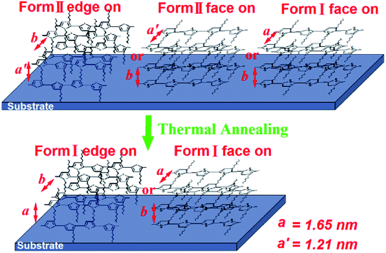 | ||
| Fig. 8 The schematic illustration of the molecular orientation and the thermal stability of the P3HT nanograting film fabricated by various solvent vapors. | ||
It is noted that the result of this manuscript may be different from the report of the Michele Perego group.39,40 Michele Perego had indicated that the methodology allowed self-organization of symmetric PS-b-PMMA thin films in a few seconds, taking advantage of the amount of solvent naturally trapped within the film during the spinning process or the synergic effect of thermal annealing with the initial solvent naturally trapped in the basic RCP + BCP system after the deposition process could be exploited to enhance the lateral order. It showed that the ordering in the cylinder forming PS-b-PMMA block copolymers can be affected significantly by the concentration and the nature of the absorbed solvent. In our paper, we demonstrate here that the molecular orientation and thermal stability of the poly(3-hexylthiophene) (P3HT) nanograting film can be affected obviously by the fabricated solvent vapor. A solvent-vapor nanoimprinting lithography (SV-NIL) technique based on a polydimethylsiloxane (PDMS) template is employed to fabricate a P3HT nanograting structure film successfully and solvent vapor is offered by chlorobenzene, chloroform and carbon disulphide, respectively. The molecular orientation of the polymer film is affected by the effect of various solvent vapors. In this paper, the performed conditions are identical for various solvent vapors (there is only a change in the solvent vapor kind) and all of the concentrations of the absorbed solvent are about 0.1 μg ml−1. Thus, according to the present results and discussion here, it can only be inferred that the formation mechanism of the desired molecule chain orientation may be induced by the combined action of the surrounding confinement (nanograting fabrication) and the nature of the solvent vapor and the detailed mechanism of orientation formation will be explored with further effort in the future (it may be affected by the concentration of the absorbed solvent).
Conclusions
In all, in this paper the SV-NIL technique based on a PDMS template is employed to fabricate a P3HT nanograting structure on the surface of a P3HT thin film. A PDMS template is chosen as the NIL mold and solvent vapor is offered by chlorobenzene, chloroform and carbon disulphide, respectively. It is simple, cost-effective and the method possesses high replication fidelity to produce the nanostructure morphology of the polymer film. The molecular orientation of the polymer film is carefully characterized by GIWAXD measurement to investigate the effect of various solvent vapors on the molecular orientation of the P3HT nanograting film. For the P3HT nanograting film fabricated by chloroform and chlorobenzene solvents, an edge-on molecular orientation of the typical form II crystallographic structure crystal is induced by the SV-NIL process. However, there is an obvious difference in the diffraction signal of the P3HT nanograting film fabricated by the carbon disulphide solvent. It indicates that there are both face-on molecular orientation of the form II and form I crystallographic conformations for the P3HT nanograting film fabricated by carbon disulphide solvent. Therefore, the fabricated solvent vapor plays a significant role in determining the formation of the molecular orientation of the polymer nanostructure. As for the annealed nanograting film fabricated by chlorobenzene and chloroform solvent vapor, a single edge-on molecular orientation mode of form I crystallographic structure can be investigated. However, for the annealed nanograting film fabricated by carbon disulphide solvent, the edge-on and face-on molecular orientation of the form I crystallographic structure is still retained. The stability of the form II crystallographic conformation is mainly dependent on the thermal annealing process. Therefore, after an annealing process, the edge-on or face-on molecular orientation of the form I crystallographic conformation can only be investigated for the annealed P3HT nanograting film and the concrete choice of molecular alignment depends significantly on the orientation type of the nanograting film before the annealing history, and it can be further inferred that the molecular orientation of the annealed polymer film is still affected by the fabricated solvent vapor. The investigation of the molecular orientation and thermal stability of the P3HT nanograting film affected by the fabricated solvent vapor will provide new understanding and guidance for the research of the topographical structure and molecular alignment of conjugated polymers.Conflicts of interest
There are no conflicts to declare.Acknowledgements
This work is financially supported by the National Natural Science Foundation of China (No. 21504028), Natural Science Foundation of Educational Committee of Anhui Province (KJ2015A119), and Anhui Provincial Innovation Team of Design and Application of Advanced Energetic Materials (KJ2015TD003). The authors also thank beamline BL14B1 (Shanghai Synchrotron Radiation Facility) for providing the beam time and help during experiments.Notes and references
- X. Chen, F. Yang, C. Zhang, J. Zhou and L. J. Guo, ACS Nano, 2016, 10, 4039–4045 CrossRef CAS.
- L. Pan, Y. Park, Y. Xiong, E. Ulin-Avila, Y. Wang, L. Zeng, S. Xiong, J. Rho, C. Sun, D. B. Bogy and X. Zhang, Sci. Rep., 2011, 1, 175 CrossRef CAS.
- M. Totzeck, W. Ulrich, A. Gohnermeier and W. Kaiser, Nat. Photonics, 2007, 1, 629–631 CrossRef CAS.
- M. Altissimo, Biomicrofluidics, 2010, 4, 026503 CrossRef.
- Y. Chen, Microelectron. Eng., 2015, 135, 57–72 CrossRef CAS.
- S. Y. Chou, P. R. Krauss and P. J. Renstrom, Appl. Phys. Lett., 1995, 67, 3114 CrossRef CAS.
- H. Park, X. Zhang, K. W. Lee, K. H. Kim, S. H. Jung and D. S. Park, et al., CrystEngComm, 2013, 15, 3463–3469 RSC.
- R. D. Piner, J. Zhu, F. Xu, S. Hong and C. A. Mirkin, Science, 1999, 283, 661–663 CrossRef CAS.
- K. Salaita, Y. Wang and C. A. Mirkin, Nat. Nanotechnol., 2007, 2, 145–155 CrossRef CAS.
- S. Y. Chou, P. R. Krauss and P. J. Renstrom, Science, 1996, 272, 85–87 CrossRef CAS.
- M. Behl, J. Seekamp, S. Zankovych, C. M. Sotomayor Torres, R. Zentel and J. Ahopelto, Adv. Mater., 2002, 14, 588–591 CrossRef CAS.
- L. J. Guo, J. Phys. D: Appl. Phys., 2004, 37, R123 CrossRef CAS.
- E. Mele, F. Di Benedetto, L. Persano, R. Cingolani and D. Pisignano, Nano Lett., 2005, 5, 1915–1919 CrossRef CAS.
- M.-S. Kim, J.-S. Kim, J. C. Cho, M. Shtein, L. J. Guo and J. Kim, Appl. Phys. Lett., 2007, 90, 123113–123116 CrossRef.
- Z. Hu, B. Muls, L. Gence, D. A. Serban, J. Hofkens, S. Melinte, B. Nysten, S. Demoustier-Champagne and A. M. Jonas, Nano Lett., 2007, 7, 3639–3644 CrossRef CAS.
- Z. Zheng, K.-H. Yim, M. S. M. Saifullah, M. E. Welland, R. H. Friend, J.-S. Kim and W. T. S. Huck, Nano Lett., 2007, 7, 987–992 CrossRef CAS.
- F. Di Benedetto, A. Camposeo, S. Pagliara, E. Mele, L. Persano, R. Stabile, R. Cingolani and D. Pisignano, Nat. Nanotechnol., 2008, 3, 614–619 CrossRef CAS.
- M. Aryal, K. Trivedi and W. Hu, ACS Nano, 2009, 3, 3085–3090 CrossRef CAS.
- X. He, F. Gao, G. Tu, D. Hasko, S. Huttner, U. Steiner, N. C. Greenham, R. H. Friend and W. T. S. Huck, Nano Lett., 2010, 10, 1302–1307 CrossRef CAS.
- H. Hlaing, X. Lu, T. Hofmann, K. G. Yager, C. T. Black and B. M. Ocko, ACS Nano, 2011, 5, 7532–7538 CrossRef CAS.
- C. Zhang, H. Subbaraman, Q. Li, Z. Pan, J. G. Ok and T. Ling, et al., J. Mater. Chem. C, 2016, 4, 5133–5153 RSC.
- H. Schmid and B. Michel, Macromolecules, 2000, 33, 3042–3049 CrossRef CAS.
- T. W. Odom, J. C. Love, D. B. Wolfe, K. E. Paul and G. M. Whitesides, Langmuir, 2002, 18, 5314–5320 CrossRef CAS.
- T. W. Odom, V. R. Thalladi, J. C. Love and G. M. Whitesides, J. Am. Chem. Soc., 2002, 124, 12112–12113 CrossRef CAS.
- B. D. Gates, Q. Xu, M. Stewart, D. Ryan, C. G. Willson and G. M. Whitesides, Chem. Rev., 2005, 105, 1171–1196 CrossRef CAS.
- K. E. Paul, M. Prentiss and G. M. Whitesides, Adv. Funct. Mater., 2005, 13, 259–263 CrossRef.
- K. L. Lai, M. H. Hon and I. C. Leu, J. Micromech. Microeng., 2011, 21, 075013 CrossRef.
- X. Yu, Z. Wang, R. Xing, S. Luan and Y. Han, Polymer, 2005, 46, 11099–11103 CrossRef CAS.
- J. Liu, Y. Sun, L. Zheng, Y. Geng and Y. Han, Polymer, 2013, 54, 423–430 CrossRef CAS.
- J. Choi, J. Jin, M. Jin, C. An and H. Jung, RSC Adv., 2014, 4, 12302–12308 RSC.
- K. Wang, X. Li, C. Wang, M. Qian, G. Ding and J. Liu, RSC Adv., 2017, 7, 40208–40217 RSC.
- G. Lu, L. Li and X. Yang, Adv. Mater., 2007, 19, 3594–3598 CrossRef CAS.
- J. Liu, Y. Sun, X. Gao, R. Xing, L. Zheng, S. Wu, Y. Geng and Y. Han, Langmuir, 2011, 27, 4212–4219 CrossRef CAS.
- R. Hegde, N. Henry, B. Whittle, H. Zang, B. Hu, J. Chen, K. Xiao and M. Dadmun, Sol. Energy Mater. Sol. Cells, 2012, 107, 112–124 CrossRef CAS.
- X. Liu, S. Huettner, Z. Rong, M. Sommer and R. H. Friend, Adv. Mater., 2012, 24, 669–674 CrossRef CAS PubMed.
- F. Chen, C. Ko, J. Wu and W. Chen, Sol. Energy Mater. Sol. Cells, 2010, 94, 2426–2430 CrossRef CAS.
- E. Verploegen, C. E. Miller, K. Schmidt, Z. Bao and M. F. Toney, Chem. Mater., 2012, 24, 3923–3931 CrossRef CAS.
- T. Yang, W. Wen, G. Yin, X. Li, M. Gao, Y. Gu, L. Li, Y. Liu, H. Lin, X. Zhang, B. Zhao, T. Liu, Y. Yang, Z. Li, X. Zhou and X. Gao, Nucl. Sci. Tech., 2015, 26, 020101 Search PubMed.
- G. Seguini, F. Zanenga, T. J. Giammaria, M. Ceresoli, K. Sparnacci, D. Antonioli, V. Gianotti, M. Laus and M. Perego, ACS Appl. Mater. Interfaces, 2016, 8, 8280–8288 CrossRef CAS.
- M. Perego, F. F. Lupi, M. Ceresoli, T. J. Giammria, G. Seguini, E. Enrico, L. Boarino, D. Antonioli, V. Gianotti, K. Sparnacci and M. Laus, J. Mater. Chem. C, 2014, 2, 6655–6664 RSC.
Footnote |
| † Electronic supplementary information (ESI) available: AFM images, GIWAXD images, and schematic indication of orientation. See DOI: 10.1039/c9ra05693a |
| This journal is © The Royal Society of Chemistry 2019 |