
 Open Access Article
 This Open Access Article is licensed under a Creative Commons Attribution-Non Commercial 3.0 Unported Licence
Investigation of Cu doped flake-NiO as an anode material for lithium ion batteries
Yue Pan *a,
Weijia Zengb,
Rong Hub,
Bo Lia,
Guiling Wang*b and
Qintang Li*a
*a,
Weijia Zengb,
Rong Hub,
Bo Lia,
Guiling Wang*b and
Qintang Li*a
aState Key Laboratory of Environment-friendly Energy Materials, Southwest University of Science and Technology, Mianyang, 621010, China. E-mail: panyuehrb@outlook.com; liqintangwind@sina.com
bKey Laboratory of Superlight Materials and Surface Technology of Ministry of Education, College of Materials Science and Chemical Engineering, Harbin Engineering University, Harbin, 150001, China. E-mail: wangguiling@hrbeu.edu.cn; Tel: +86-451-82589036
First published on 5th November 2019
Abstract
Cu foil is widely used in commercial lithium ion batteries as the current collector of anode materials with excellent conductivity and stability. In this research, commercial Cu foil was chosen as the current collector and substrate for the synthesis of Cu doped flake-NiO via a traditional hydrothermal method. The effect of the ratio of Cu and the calcination temperature on the electrochemical performance of NiO was investigated. The structure and phase composition of the Cu doped flake-NiO electrode were studied through X-ray diffraction (XRD), scanning electron microscopy (SEM), Energy dispersive X-ray analysis (EDAX), transmission electron microscopy (TEM), X-ray photoelectron spectroscopy (XPS) and inductive coupled plasma emission spectrometry (ICP). The electrochemical properties of the Cu doped flake-NiO electrode were studied through cyclic voltammetry (CV), electrochemical impedance spectroscopy (EIS) and a galvanostatic charge–discharge cycling technique. According to the results, the Cu-doped NiO electrode, calcined at 400 °C with a molar ratio of Cu![[thin space (1/6-em)]](https://www.rsc.org/images/entities/char_2009.gif) :Ni = 1:8, exhibited a high reversible charge capacity. The good cycling stability and rate performance indicate that the as-prepared electrode can be applied as a potential anode for lithium ion batteries.
:Ni = 1:8, exhibited a high reversible charge capacity. The good cycling stability and rate performance indicate that the as-prepared electrode can be applied as a potential anode for lithium ion batteries.
1 Introduction
In the last decade, the global economy is taking on a trend of accelerating development. To match the urgent need for energy, a green and renewable energy that can become the next generation of power instead of fossil fuels is one of the biggest scientific problems.1,2 Lithium ion batteries (LIBs), a device of energy transition and storage, have attracted more and more attention from researchers for their outstanding energy density, environmental benignity and long cycling life.3–5 Since the birth of commercial LIBs in the early 1990s by the Sony Corporation, graphite as the most widely used anode material has been in dispute for a long time. This issue is caused by the poor theoretical capacity (372 mA h g−1) and low lithiation potential of graphite (the reason for the formation of Li dendrite) but it has low price and good conductivity.6–9 Therefore, we need to develop the alternative anode materials to match the requirements of next-generation LIBs. In the past decades, several different types of anode materials have been studied, such as Lithium titanate,10 transition metal oxides,11 Si/Sn based alloys,12,13 etc.Transition metal oxides are highlighted for their high theoretical capacities (∼1000 mA h g−1). For examples, FeOx (x = 1, 4/3, 3/2),14 CoOy (y = 1, 4/3, 3/2),15 NiO,16 CuO17 and TiO2 (ref. 18) have been widely studied as promising anode materials for LIBs. Among them, NiO has attracted much attention because of its low cost, relatively high theoretical capacity (718 mA h g−1) and environmental-friendly feature. However, the volume expansion and particle aggregation during the cycling has limited its application. Since the first report by Poizot in 2000,11 many researchers have been absorbed in the study about NiO anode material. And the main ideas are shorting the diffusion pathway of reversible intercalation/deintercalation of Li ions among the active particles, relieving the volume expansion of active materials and improving the conductivity. Practical actions based on these main ideas have been carried out efficiently by synthesizing the nano-sized active materials or thin film, coating high conductive materials on the surface of active particles and conducting composite materials by introducing foreign metallic elements.
X. H. Hang's group prepared hollow microspheres of NiO as anode materials for LIBs in 2010,19 and the charge capacity was delivered to 490 mA h g−1 after 45 cycles at 100 mA g−1. L. J. Zhang's group designed CoO–NiO–C anode materials for LIBs in 2012,20 and a reversible capacity around 562 mA h g−1 was showed at 0.1 A g−1 after 60 cycles. H. L. Zhao's group synthesized NiO/Ni nanocomposite anode material for LIBs in 2015,21 and a reversible capacity of 800 mA h g−1 was maintained at 0.1C after 50 cycles. And X. F. Li's group conducted a flower-like NiO/RGO anode materials for LIBs in 2018,22 and a reversible capacity of 702.3 mA h g−1 was maintained at 0.1 A g−1 after 100 cycles. L. K. Pan's group reported yolk–shell ZnO/NiO microspheres. The reversible charge specific capacity was 1008.6 mA h g−1 at 0.1 A g−1 after 200 cycles.23 While the study about Cu-doped NiO as an anode material for LIBs is relatively young.
In this work, we successfully designed a binder free NiO on cupper foil with a flake morphology via a facial and highly reproduced hydrothermal method. The flake structure can shorten the diffusion path of Li+ and buffer the volume expansion of active material itself. To improve the conductivity, we tried to load Cu element in to the crystal structure of NiO. The effect of the content of Cu and the calcined temperature is further identified to improve the electrochemical performance of NiO. In this way, we reserved a best modified NiO with excellent cycling stability and rate performance.
2 Experimental section
2.1 The preparation of Cu doped flake-NiO
Flake-structured NiO has been synthesized by a hydrothermal method displayed in Scheme 1. Firstly, the Cu foil (Dongguan xuran Electronic Technology Co., Ltd, Cell Grade) as the current collector and substrate was cleaned alternatively by deionized water and acetone under ultrasonic for 5 min and placed into a 100 ml reaction kettle afterwards. After dispersing 1 mol L−1 NiCl2·6H2O (Aladdin, analytical reagent), x mol L−1 CuCl2·2H2O (Aladdin, analytical reagent), x = 0, 1/18, 1/4, 1/10, 1/8 and 1/6), and 0.2 mol L−1 NH4F (Aladdin, analytical reagent) into 0.5 mol L−1 urea (Aladdin, analytical reagent), the mixture was poured into the reaction kettle merging the Cu foil. Secondly, the reaction kettle was located into a preheated oven (120 °C) for 5 h. After cooling to room temperature, the Cu foil deposited with a green layer was washed serially with deionized water for several minutes and dried in vacuum oven for 18 h. Finally, black Cu-doped NiO electrode was conducted by a calcination process in a tube furnace under argon for 2 h at different temperatures. | ||
| Scheme 1 The preparation of binder free flake Cu doped NiO electrode. | ||
2.2 The fabrication of half cell
The coated Cu foil was cut into small pieces with a diameter of 14.0 mm and worked as the working electrode with a mass loading around 3.0 mg cm−2. Li foil (analytical reagent) with a diameter of 15.0 mm served as both the counter and reference electrode. 1 M LiPF6 dissolved in a ternary solvent of isometric ethyl carbonate (EC), ethyl methyl carbonate (EMC) and dimethyl carbonate (DMC) was used as the electrolyte and Cellgard 5300 worked as the separator. The fabrication of all the half cells was kept operating in argon glove box (H2O < 0.1 ppm, O2 < 0.1 ppm).2.3 The characterization and electrochemical test
The morphology and crystal structure of Cu doped NiO were characterized with X-ray diffractometer (XRD, D/max-TTR III) from 10–80° with a scan rate of 5° min−1 at room temperature, scanning electron microscopy (SEM, JSM-6480A), transmission electron microscopy (TEM, CM-200FEG) and X-ray photoelectron spectroscopy (XPS, ESCALAB 250Xi). The content of Cu in the as-prepared composite was determined by inductive coupled plasma emission spectrometer (ICP, Xseries II). The charge/discharge measurements were carried on a Land BT2000, between 0.05–3.0 V (vs. Li+/Li) at room temperature under different current densities. Electrochemical impedance spectroscopy (EIS) and cyclic voltammetry (CV) were carried out on a Dutch Autolab at room temperature. The frequency was ranging from 200 kHz to 0.1 Hz, while the voltage was ranging from 0.05–3.0 V (vs. Li+/Li) with a sweeping speed of 0.1 mV s−1, respectively.3 Results and discussion
3.1 The effect of the Cu ratio on the electrochemical performance of NiO
To detect the effect of the Cu ratio on the electrochemical performance of NiO electrode, six different prescriptions are exploited (the molar ratio between Cu and Ni is 0, 1/18, 1/14, 1/10, 1/8 and 1/6).Fig. 1 shows the XRD patterns of the six composites calcined at 350 °C. In the XRD pattern of raw NiO (black line), four strong diffraction peaks can be observed. The pattern between 43° and 44° is magnified and another diffraction peak can be clearly distinguished. After reasonable analysis and comparison, it can be concluded that the diffraction peaks at 37.2°, 43.2° and 62.9° correspond to the (111), (200) and (220) lattice planes of NiO (JCPDS No. 04-0835) and the diffraction peaks at 43.5°, 50.7° and 74.7° are indexed to the metal Cu foil (metal Cu, JCPDS No. 01-1242). After the addition of 1/18 Cu, the XRD pattern of the product is quite similar with that of raw NiO and only the strength of the peak changes slightly. With the continuous addition of Cu, the XRD patterns of all the products hardly change except for the strength of the peaks. Meanwhile, there are no other peaks, illustrating no impurities introduced to the as-prepared electrodes. It seems that the added Cu neither destroys the structure of the host (NiO) nor forms other cupper oxides, and Cu foil is well protected without any oxidation in the Ar atmosphere.
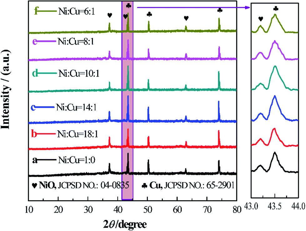 | ||
| Fig. 1 XRD patterns of different Cu doped NiO on Cu foil. | ||
The morphology of the six samples was characterized by SEM shown in Fig. 2. In Fig. 2a, the sample of raw NiO has a uniform flake structure with a thickness around 100 nm and the flakes are overlapped with each other. The large space among the overlapped flakes can contain rich electrolyte and shorten the transmission path of Li ions between the electrolyte and the active material. When the Cu is added during the preparation of NiO, the morphology of the product (Fig. 2b–f) does not change compared with that of raw NiO (Fig. 2a). Interestingly, the thickness of the flake has a slight decrease after the modification process. It seems that the addition of Cu during the preparation process can thin the thickness of the NiO flake, which could effectively shorten the diffusion path of the Li+ into the internal of the flakes and the space set by the adjacent flakes could alleviate the volume expansion of active material during the charge/discharge process.
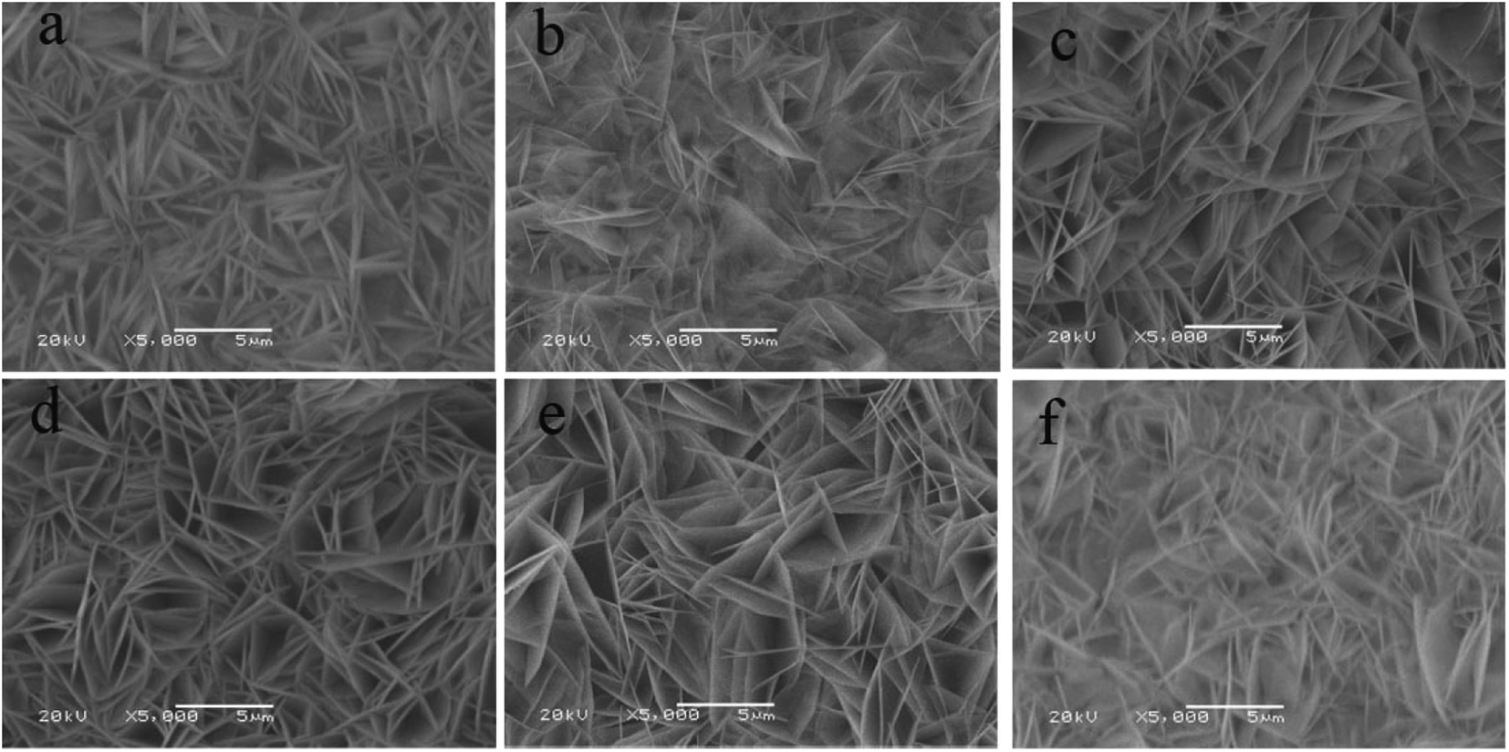 | ||
| Fig. 2 The SEM images of different Cu doped NiO on Cu foil, Cu:Ni = 0 (a), 1/18 (b), 1/14 (c), 1/10 (d), 1/8 (e) and 1/6 (f). | ||
The electrochemical test is an efficient method to value the performance of the samples as anode materials for LIBs. These measurements were carried out on the fabricated of the half cells. Fig. 3 displays the cycling performances of the six samples tested at 0.1C (1C = 1000 mA g−1), and the electrodes are marked as Cu–NiO-x. The charge capacity of raw NiO electrode in the first cycle is 815.2 mA h g−1. In the following cycles It drops dramatically to 381.4 mA h g−1 at the 20th cycle and then slowly to 252.5 mA h g−1 at the 50th cycle. For the Cu doped NiO electrode with Cu:Ni = 1:18, the first charge capacity is as high as 1096.2 mA h g−1. It decreases rapidly to 456.1 mA h g−1 in the 20th cycle and keeps relatively steady to 387.4 mA h g−1 in the 50th cycle. With the increase of the content of Cu, the electrodes of Cu–NiO-1/14 and Cu–NiO-1/10 show better cycling performance. When the content of Cu increases to Cu:Ni = 1:8, the electrode reveals the best performance. The charge capacity in the 50th cycle can retain 655.3 mA h g−1. However, when the content of Cu increases further to Cu:Ni = 1:6, the performance has a severe drop with a charge capacity of 462.3 mA h g−1 in the 50th cycle. To sum up, the reversible capacity of Cu–NiO-1/8 after 50 cycles is 655.3 mA h g−1, which is 402.8, 267.9, 105.2, 60.9 and 193.0 mA h g−1 higher than those of the electrodes of raw NiO, Cu–NiO-1/18, Cu–NiO-1/14, Cu–NiO-1/10 and Cu–NiO-1/6, respectively. The brilliant cycling performance of the Cu–NiO-1/8 electrode is due to the special flake structure and the suitable scale of Cu and Ni, which means that it is very important and necessary to control the ratio between Cu and Ni. This result can be legitimately supported by the date of EIS in Fig. 4, where the resistance of charge transfer is effectively reduced with the addition of Cu and the minimum value is obtained with a molar ratio of Cu:Ni = 1:8.
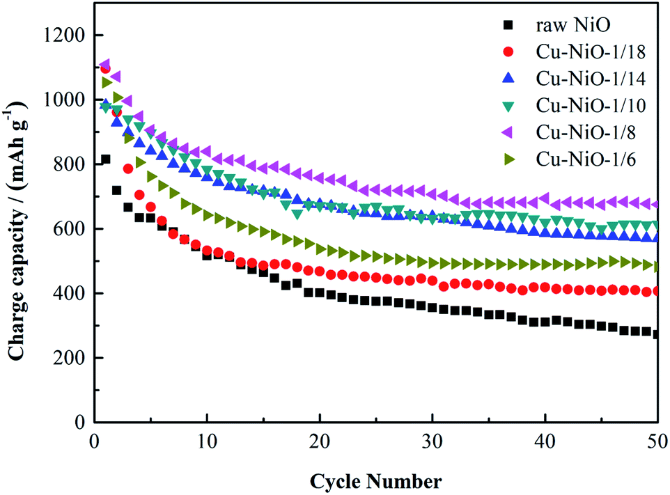 | ||
| Fig. 3 Cycling stability of different Cu doped NiO on Cu foil. | ||
 | ||
| Fig. 4 EIS spectra of different Cu doped NiO on Cu foil. | ||
To gain an insight into the outstanding performance of the Cu–NiO-1/8 electrode, ICP, TEM and XPS characterizations have been carried out. According to the result of the ICP test, the molar ratio of Cu:Ni in the Cu–NiO-1/8 is close to the original amount, i.e. Cu:Ni = 1:8. Fig. 5 presents the TEM and HRTEM images of the raw NiO and Cu–NiO-1/8, respectively. In Fig. 5a and b, the obvious flake structure can be observed for both the raw NiO and Cu–NiO-1/8, which is consist with the SEM results in Fig. 2. The thickness of the Cu–NiO-1/8 flake in Fig. 5b is thinner than that of NiO in Fig. 5a for the light transmittance exhibited in Fig. 5b is much higher. This is in keeping with the results observed thorough the SEM. Therefore, it is demonstrated that the addition of Cu can refine the thickness of NiO flake. In the HRTEM images, there are two different structurally uniform lattice fringes of both NiO and Cu–NiO-1/8 corresponding to the (111) and (200) lattice planes (JCPDS No. 04-0835), respectively.
 | ||
| Fig. 5 The TEM images of pure NiO (a) and Cu–NiO-1/8 (b); HRTEM images of pure NiO (c) and Cu–NiO-1/8 (d). | ||
Fig. 6 reveals the Cu 2p and Ni 2p spectra. In Fig. 6a, the binding energy values of the two major peaks are 932.3 and 743.8 eV in the Cu 2p spectrum, associated with Cu 2p3/2 and Cu 2p1/2, respectively. Meanwhile, a weak satellite peak at 943.8 eV corresponds to Cu 2p3/2. The result means that Cu cation is assigned as a value of +2.24,25 In Fig. 6b, there are two main peaks at 854.7 eV and 872.3 eV, which should be attributed to the Ni 2p3/2 and Ni 2p1/2. And two satellite peaks at 860.5 eV and 878.9 eV correspond to Ni 2p3/2 and Ni 2p1/2, respectively. These results demonstrate that Ni cation can be assigned a value of +2.26,27 Moreover, the elemental mapping (Fig. 7) reveals that the Cu is uniformly disperse in the sample of Cu–NiO-1/8.
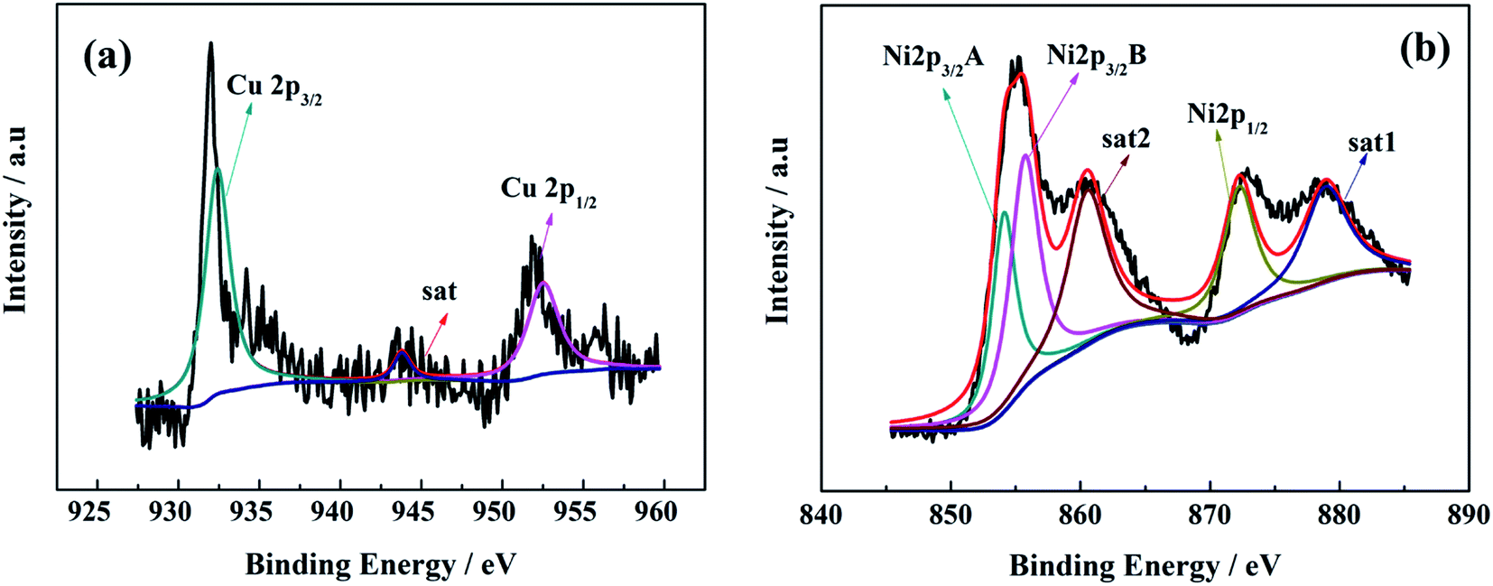 | ||
| Fig. 6 XPS spectra of Cu 2p (a) and Ni 2p (b) in Cu–NiO-1/8. | ||
 | ||
| Fig. 7 Elemental mapping of Cu–NiO-1/8. | ||
Above all the results (XRD, HRTEM, ICP, XPS and SEM-mapping), it can be concluded that NiO has been doped with Cu successfully and Cu2+ partly replaced Ni2+ in NiO. Mostly, the modified electrode with Cu:Ni = 1:8 shows the best performance because of its special flake structure and the exactly suitable molar ratio of Cu2+/Ni2+.
3.2 The effect of calcination temperature on the electrochemical performance of Cu–NiO-1/8
As the calcination temperature has an important effect on the structure of the product, the precursor of Cu–NiO-1/8 was calcinated at three different temperatures (350 °C, 400 °C and 450 °C). The XRD patterns of Cu–NiO-1/8 calcined at different temperatures are displayed in Fig. 8. In the XRD patterns, there are only peaks from NiO (2θ = 37.2°, 43.2° and 62.9°) and Cu foil (2θ = 43.5°, 50.7° and 74.7°), which can demonstrate the designated calcination temperature did not change the crystal structure of the products. Noticeably, the strength of the peaks from NiO increases with the temperature, indicating that the degree of crystallinity increases with the calcination temperature.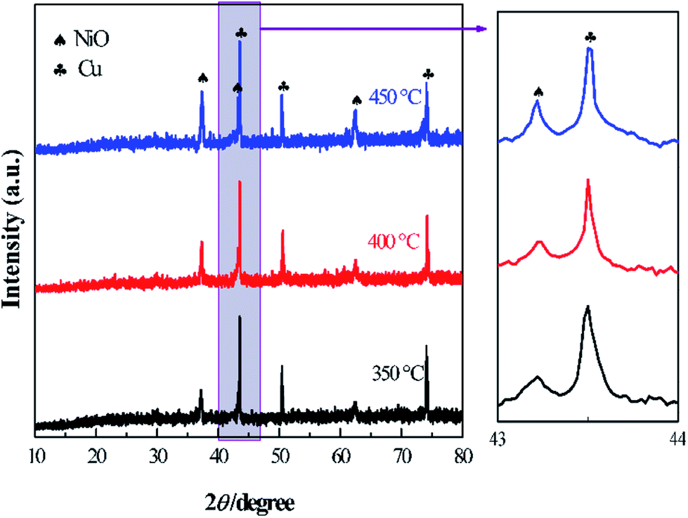 | ||
| Fig. 8 XRD patterns of the Cu–NiO-1/8 calcined at 350 °C, 400 °C and 450 °C. | ||
The SEM images of Cu–NiO-1/8 calcined at 350 °C, 400 °C and 450 °C are shown in Fig. 9. These three samples exhibit similar flake structure. By comparing the SEM images (Fig. 9b, d and f), the thickness of the flake has a slightly decrease when the calcination temperature rises from 350 °C to 400 °C. However, when the calcination temperature rises to 450 °C, the thickness of the flakes has an obvious increase and the flakes obviously agglomerated.
 | ||
| Fig. 9 SEM images of Cu–NiO-1/8 calcined at 350 °C (a and b), 400 °C (c and d) and 450 °C (e and f). | ||
The cycling performance of Cu–NiO-1/8 electrodes calcined at different temperatures under a current density of 100 mA g−1 (0.1C) is exhibited in Fig. 10a. At 350 °C, it can be observed that the first charge capacity is around 1108.9 mA h g−1. It drops rapidly to 906.0 mA h g−1 in the 5th cycle and decreases slowly to 709.1 mA h g−1 in the 25th cycle. In the following cycles, the change of the charge capacity is relatively unnoticeable. After 50 cycles, the charge capacity is stable at 655.3 mA h g−1. When the calcination temperature increased to 400 °C, the trend of the cycling performance is similar with that calcined at 350 °C. And the reversible capacity is 1131.9, 913.6, 773.1 and 714.4 mA h g−1 in the 1st, 5th, 25th and 50th cycle, respectively. While the calcination temperature is up to 450 °C, the trend of the cycling performance has a huge change. The charge capacity in the 1st cycle is much higher than the other two, but the value has a dramatic drop in the first 25 cycles. The charge capacity decreases to 514.4 mA h g−1 in the 25th cycle and keeps stable in the following cycles. After 50 cycles, the charge capacity is stabilized at 482.3 mA h g−1. It is clearly exhibited that the reversible capacity of Cu–NiO-1/8 electrode calcined at 400 °C after 50 cycles is 59.1 and 232.1 mA h g−1 higher than those of Cu–NiO-1/8 electrode calcined at 350 and 450 °C, respectively. The remarkable performance of the Cu–NiO-1/8 electrode calcined at 400 °C can be attributed to the thin flake structures and higher specific surface area supported by the results in Fig. 9. Praiseworthily, the Cu–NiO-1/8 electrode calcined at 400 °C shows a markedly improved reversible capacity than that of NiO electrodes reported previously, as shown in Table 1.
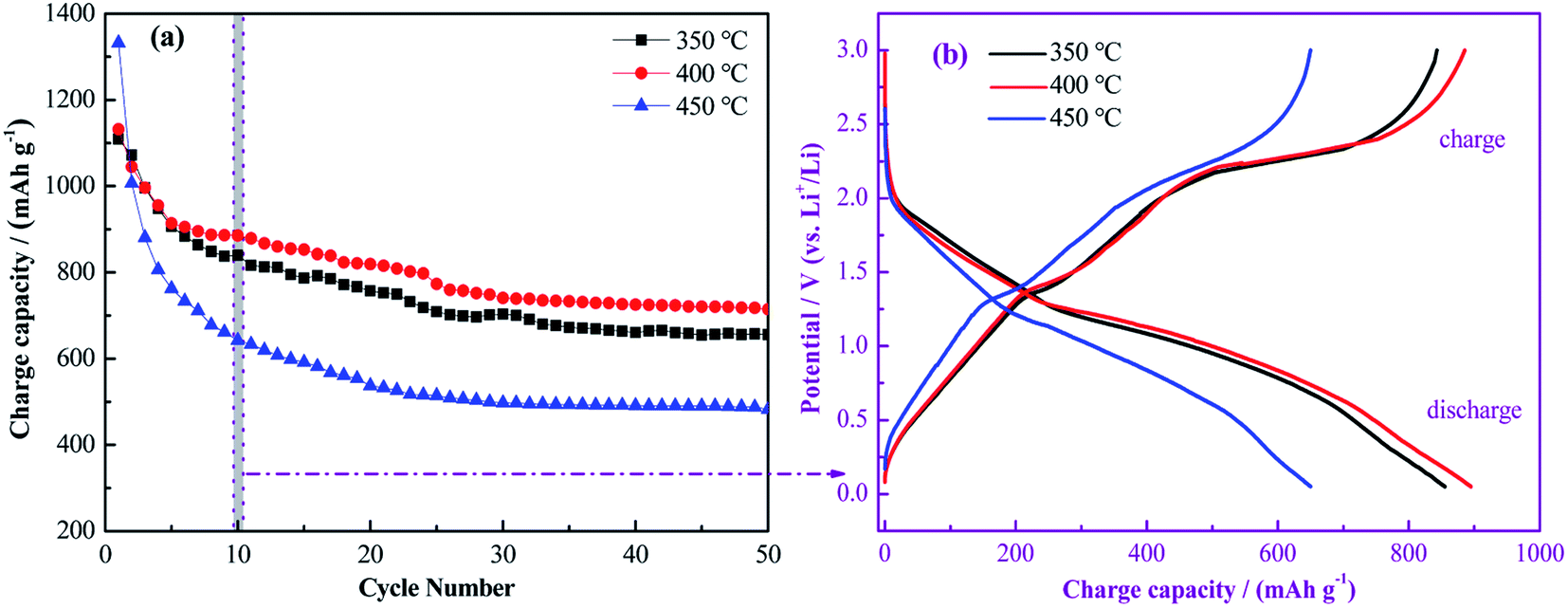 | ||
| Fig. 10 Cycling performance of Cu–NiO-1/8 calcined at different temperatures (a); the charge/discharge curves in the 10th cycle (b). | ||
| Samples | Cycle number | Reversible capacities (mA h g−1) | Reference |
|---|---|---|---|
| NiO hollow microsphere | 45 | 490 (100 mA g−1) | 19 |
| CoO–NiO–C | 60 | 562 (100 mA g−1) | 20 |
| 3D flower like NiO | 40 | 713 (100 mA g−1) | 28 |
| NiO nanosphere | 60 | 518 (100 mA g−1) | 29 |
| CuNiO/carbon nanotube | 50 | 686 (100 mA g−1) | 30 |
| CuO–NiO nanocomposites | 50 | 562.5 (100 mA g−1) | 31 |
| Cu–NiO-1/8 flake | 50 | 714.4 (100 mA g−1) | This work |
In Fig. 10b, the charge/discharge curves of the three samples in the 10th cycle are selected because the charge capacity is relatively stable after the first 10 cycles (Fig. 10a). In the discharge process of the Cu–NiO-1/8 electrode calcined at 350 °C, the potential decreases rapidly to ∼2.0 V and gently to ∼1.25 V, followed by along plateau between 1.25 and 0.75 V, corresponding to the decomposition of NiO into Ni. And an inclined plateau is observed around 2.25 V in the charge process, which can be ascribed to the oxidation of Ni into NiO. The shapes of the three couples of the charge/discharge curves are similar, except the range of the oxidation/reduction plateau changes with the calcination temperature.
To have a further study on the mechanism and the electrochemical performance of the as-prepared Cu–NiO-1/8 electrodes, CV and EIS measurements were carried out with results shown in Fig. 11. The mechanism of NiO as anode materials for LIBs have been proposed as:6,32
discharge:
| NiO + 2Li+ + 2e− → Ni + Li2O; |
charge:
| Ni + Li2O − 2e− →NiO + 2Li+. |
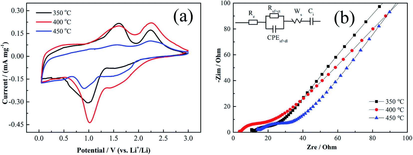
Based on this mechanism, the theoretical specific capacity value can be calculated by Faraday law as ∼718 mA h g−1. The CV curves of Cu–NiO-1/8 calcined at different temperatures in the 3rd cycles are picked, because the CV curves in the first cycles would show the large irreversible capacity and be interfered by the “additional reaction”, which is related to the formation of solid electrochemical interface (SEI) and amorphous Li2O. In the cathodic scan, there are one weak peak around 1.42 V and one strong peak around 1.0 V, corresponding to the formation of SEI and the conversion of NiO to Ni, respectively.30 While in the anodic scan, there are also two different oxidation peaks. One weak oxidation peak around 1.58 V is related to the decomposition of SEI and the other strong peak around 2.25 V is consistent with the oxidation of Ni to NiO.33 The couple peaks of the formation/decomposition of SEI can also explain the extra capacity of the as-prepared flake Cu–NiO electrodes, whose reversible capacity displayed in Fig. 3 and 9 is somewhat higher than the theoretical value of NiO (∼718 mA h g−1). Additionally, the potentials of all the oxidation/reduction peaks are consistent with the results showed in the charge/discharge curves (Fig. 10b) and these results are similar with those previous researches.34,35 Although the shapes of the three CV curves do not have an obvious distinction, the strength of the peaks is closely impacted by the calcination temperature of the samples. The strength of the couple peaks of the conversion between NiO and Ni increases when the calcination temperature rises to 400 °C, and dramatically decreases when the temperature reaches 450 °C. This is ascribed to the different electrochemical performances of the three electrodes: good performance with stronger peaks.
In the impedance spectra of Cu–NiO-1/8 calcined at different temperatures (Fig. 11b), the insert is the fitted equivalent circuit. It can be seen that Cu–NiO-1/8 calcined at 400 °C reveals the lowest Re (2.84 Ω) and R(sf+ct) (3.50 Ω) values, suggesting significantly improved electron conductivity and charge transition on the electrode–electrolyte interface. The results from the special flake structure with moderate thickness, which is closely related to the added content of Cu element and calcination temperature. The most suitable flakes can shorten the pass route of Li+ and alleviate the volume expansion of active material during the charge/discharge process, by which the capacity and stability can be significantly improved. The results from the CV and EIS can give better explanation of the excellent electrochemical performances showed in Fig. 10.
 | ||
| Fig. 11 The CV curves (a) and EIS spectra (b) of the Cu–NiO-1/8 calcined at different temperatures. | ||
Re (Ω), electrolyte resistance, R(sf+ct) (Ω), surface film + charge transfer resistance, CPE(sf+dl) (μF), constant phase element due to surface film + double layer capacitance, Ws (Ω), Warburg resistance, Ci(μF), intercalation capacitance.
The rate performance of the three samples is presented in Fig. 12. After 5 cycles at 0.1C, the Cu–NiO-1/8 electrodes calcined at 350 °C, 400 °C and 450 °C show the reversible capacity of 849.3, 920.3 and 757.7 mA h g−1. At a current density of 0.2C after 20 cycles, these values decrease to 727.7, 862.9 and 628.3, respectively. When the current density continuously increases to 1C, the reversible capacity of the electrodes can still retain 507.2, 545.8 and 380.1 mA h g−1. As the current density returns back to 0.1C, the reversible capacity of the Cu–NiO-1/8 electrodes can remain at 652.8, 744.2 and 522.0 mA h g−1, respectively. Even if being cycled after four different current densities for 20 cycles, the reversible capacity of Cu–NiO-1/8 electrode calcined at 400 °C could still keep at a value of 744.2 mA h g−1, which is 222.2 mA h g−1 higher than that calcined at 450 °C and 91.4 mA h g−1 higher than that calcined at 350 °C. As mentioned above, Cu–NiO-1/8 electrodes calcined at 400 °C also presents particularly improved rate performance compared with the other two electrodes. Long-term cycling performance is critical for the applications of LIBs. As shown in Fig. 13, the Cu–NiO-1/8 calcined at 400 °C under a current density of 0.5C (0.5 A g−1) can still deliver a reversible capacity of 503.4 mA h g−1 after 210 cycles. And the coulombic efficiency is very stable and close to 100% except the first 3 cycles.
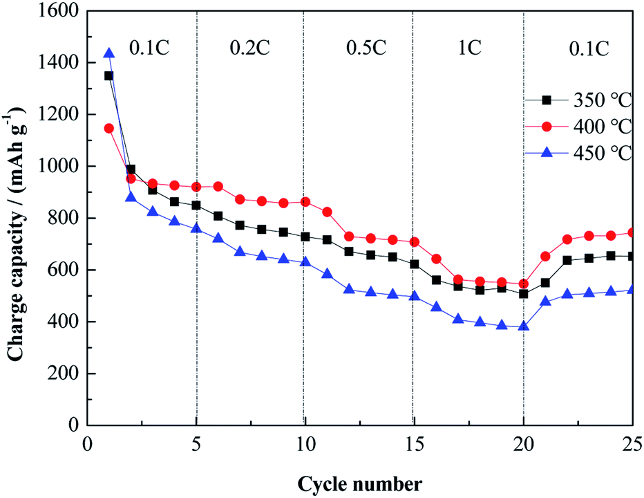 | ||
| Fig. 12 Rate performance of Cu–NiO-1/8 calcined at different temperatures. | ||
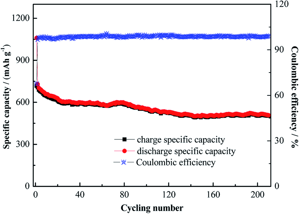 | ||
| Fig. 13 Long-term cycling performance of Cu–NiO-1/8 calcined at 400 °C under a current density of 0.5C. | ||
Based on all the experimental results above, the best electrochemical performance is achieved by the Cu–NiO-1/8 electrode with a calcination temperature of 400 °C. Firstly, the doping of Cu into the lattice of NiO and the exactly suitable molar ratio of Cu2+/Ni2+ can efficiently lower the resistance of the charge transfer process between the electrolyte and the electrode. Then the specific flake structure with preferable thickness can shorten the of Li ions. In other words, the improved electrochemical performance of the electrode should be ascribed to the synergetic effect of both the optimal level of Cu doping and the thinned flake structure.
4 Conclusion
In conclusion, a novel Cu-doped flake NiO electrode has been synthesized successfully on Cu foil by a traditional hydrothermal method. The unique structure of the as-prepared electrode exhibited a huge specific surface area and excellent electrochemical property, and the Cu–NiO-1/8 calcined at 400 °C shows a competitive electrochemical performance. The reversible charge capacity could maintain at 714.4 mA h g−1 after 50 cycles under 0.1C and 503.4 mA h g−1 after 210 cycles under 0.5C, respectively. Meanwhile, the as-prepared electrode showed excellent rate performance. All the results indicated the Cu–NiO-1/8 electrode calcined at 400 °C should be a promising electrode material for LIBs.Conflicts of interest
There are no conflicts to declare.Acknowledgements
We gratefully acknowledge the financial support of this research by the China Postdoctoral Science Foundation (2018M633401), the scientific research fund of Southwest University of Science and Technology (18zx7109), the National Natural Science Foundation of China (21703175), and the scientific research fund of Southwest University of Science and Technology (18zx7107).References
- J. M. Tarascon and M. Armand, Nature, 2001, 414, 359–361 CrossRef CAS.
- A. M. Al-Enizi, A. A. Elzatahry, A. M. Abdullah, M. A. AlMaadeed, J. X. Wang and D. Y. Zhao, Carbon, 2014, 71, 276–283 CrossRef CAS.
- X. L. Huang, R. Z. Wang, D. Xu, Z. L. Wang, H. G. Wang, J. J. Xu, Z. Wu, Q. C. Liu, Y. Zhang and X. B. Zhang, Adv. Funct. Mater., 2013, 23, 4345–4353 CrossRef CAS.
- M. Winter and R. J. Brodd, Chem. Rev., 2004, 104, 4245–4269 CrossRef CAS.
- J. J. Wang, Y. C. K. Chen-Wiegart and J. Wang, Chem. Commun., 2013, 49, 6480–6482 RSC.
- N. S. Spinner, A. Palmieri, N. Beauregard, L. C. Zhang, J. Campanella and W. E. Mustain, J. Power Sources, 2015, 276, 46–53 CrossRef CAS.
- J. F. Li, L. Han, X. J. Zhang, G. Zhu, T. Q. Chen, T. Q. Chen, T. Lu and L. K. Pan, Chem. Eng. J., 2019, 370, 800–809 CrossRef CAS.
- F. M. Courtel, H. Duncan, Y. Abu-Lebdeh and I. J. J. Davidson, J. Mater. Chem., 2011, 21, 10206–10208 RSC.
- J. B. Li, J. L. Li, Z. B. Ding, X. L. Zhang, Y. Q. Li, T. Lu, Y. F. Yao, W. J. Mai and L. K. Pan, Chem. Eng. J., 2019, 378, 122108 CrossRef CAS.
- B. G. Lee and S. H. Lee, J. Power Sources, 2017, 343, 545–549 CrossRef CAS.
- P. Poizot, S. Laruelle, S. Grugeon, L. Dupont and J. M. Tarascon, Nature, 2000, 407, 496–499 CrossRef CAS.
- Q. B. Zhang, H. X. Chen, L. L. Luo, B. T. Zhao, H. Luo, X. Han, J. W. Wang, C. M. Wang, Y. Yang, T. Zhu and M. L. Liu, Energy Environ. Sci., 2018, 11, 669–681 RSC.
- H. X. Shi, Z. W. Fang, X. Zhang, F. Li, Y. W. Tang, Y. M. Zhou, P. Wu and G. H. Yu, Nano Lett., 2018, 18, 3193–3198 CrossRef CAS.
- Y. Pan, Y. Zhang, X. P. Wei, C. L. Yuan, J. L. Yin, D. X. Cao and G. L. Wang, Electrochim. Acta, 2013, 109, 89–94 CrossRef CAS.
- Y. G. Li, B. T. Li and Y. Y. Wu, Nano Lett., 2008, 8, 265–270 CrossRef CAS.
- G. H. Yue, Y. C. Zhang, C. G. Wang, X. X. Zhang, X. Q. Zhang and Q. S. Xie, Electrochim. Acta, 2015, 152, 315–322 CrossRef CAS.
- Y. Pan, K. Ye, D. X. Cao, Y. J. Li, Y. Y. Dong, T. T. Niu, W. J. Zeng and G. L. Wang, RSC Adv., 2014, 4, 64756–64762 RSC.
- S. Nagpure, Q. L. Zhang, M. A. Khan, S. Z. Islam, J. G. Xu, J. Strzalka, Y. T. Cheng, B. L. Knutson and S. E. Rankin, Adv. Funct. Mater., 2018, 28, 1801849 CrossRef.
- X. H. Huang, J. P. Tu, C. Q. Zhang and F. Zhou, Electrochim. Acta, 2010, 55, 8981–8985 CrossRef CAS.
- Y. F. Wang and L. J. Zhang, J. Power Sources, 2012, 209, 20–29 CrossRef CAS.
- Q. Xia, H. L. Zhao, Y. Q. Teng, Z. H. Du, J. Wang and T. H. Zhang, Mater. Lett., 2015, 142, 67–70 CrossRef CAS.
- X. J. Li, L. L. Feng, X. F. Li, H. Shan, C. Chen, B. Yan, D. B. Xiong and D. Li, Mater. Chem. Phys., 2018, 217, 547–552 CrossRef CAS.
- J. B. Li, D. Yan, S. J. Hou, T. Lu, Y. F. Yao, D. H. C. Chua and L. K. Pan, Chem. Eng. J., 2018, 335, 579–589 CrossRef CAS.
- C. K. Wu, M. Yin, S. O'Brien and J. T. Koberstein, Chem. Mater., 2006, 18, 6054–6058 CrossRef CAS.
- L. Martin, H. Martinez, D. Poinot, B. Pecquenard and F. Le Cras, J. Phys. Chem. C, 2013, 117, 4421–4430 CrossRef CAS.
- X. L. Sun, C. L. Yan, Y. Chen, W. P. Si, J. W. Deng, S. Oswald, L. F. Liu and O. G. Schmidt, Adv. Energy Mater., 2014, 4, 1300912 CrossRef.
- A. Emamdoust and S. F. Shayesteh, J. Alloys Compd., 2018, 738, 432–439 CrossRef CAS.
- Q. Li, Y. J. Chen, T. Yang, D. N. Lei, G. H. Zhang, L. Mei, L. B. Chen, Q. H. Li and T. H. Wang, Electrochim. Acta, 2013, 90, 80–89 CrossRef CAS.
- G. H. Zhang, Y. J. Chen, B. H. Qu, L. L. Hu, L. Mei, D. N. Lei, Q. L. Li, B. Chen, Q. H. Li and T. H. Wang, Electrochim. Acta, 2012, 80, 140–147 CrossRef CAS.
- S. M. Abbas, S. T. Hussain, S. Ali, N. Ahmad, N. Ali, S. Abbas and Z. Ali, J. Solid State Chem., 2013, 202, 43–50 CrossRef.
- H. Chen, C. L. Li, N. Li, K. X. Xiang and Z. L. Hu, Micro Nano Lett., 2013, 8, 544–548 CrossRef CAS.
- B. Varghese, M. V. Reddy, Z. Yanwu, C. S. Lit, T. C. Hoong, G. V. S. Rao, B. V. R. Chowdari, A. T. S. Wee, C. T. Lim and C. H. Sow, Chem. Mater., 2008, 20, 3360–3367 CrossRef CAS.
- S. H. Choi and Y. C. Kang, ACS Appl. Mater. Interfaces, 2014, 6, 2312–2316 CrossRef CAS.
- X. L. Chen, T. Xiao, S. L. Wang, J. Li, P. Xiang, L. H. Jiang and X. Y. Tan, Mater. Chem. Phys., 2019, 222, 31–36 CrossRef CAS.
- G. H. Yue, Y. C. Zhao, C. G. Wang, X. X. Zhang, X. Q. Zhang and Q. S. Xie, Electrochim. Acta, 2015, 152, 315–322 CrossRef CAS.
| This journal is © The Royal Society of Chemistry 2019 |