 Open Access Article
A ZrO2-RGO composite as a support enhanced the performance of a Cu-based catalyst in dehydrogenation of diethanolamine†
Yongsheng
Wang
 ab,
Zhenzhen
Zhao
 ab,
Yunlu
Zhao
ab,
Xiaolin
Lan
ab,
Yunlu
Zhao
ab,
Xiaolin
Lan
 a,
Weixiang
Xu
 ab,
Li
Chen
ab,
Dongjie
Guo
ab and
Zhengkang
Duan
ab,
Li
Chen
ab,
Dongjie
Guo
ab and
Zhengkang
Duan
 *ab
*ab
aCollege of Chemical Engineering, Xiangtan University, Xiangtan 411105, Hunan, China. E-mail: dzk0607@163.com; Tel: +8618907325698
bHunan Collaborative Innovation Center of New Chemical Technologies for Environmental Benignity and Efficient Resource Utilization, Xiangtan 411105, Hunan, China
First published on 25th September 2019
Abstract
The sintering resistance of supported Cu nanoparticle (NP) catalysts is crucial to their practical application in the dehydrogenation of diethanolamine (DEA). In this paper, co-precipitation, hydrothermal synthesis, and sol–gel condensation are used to form a new support material through chemical bonding between graphene oxide and ZrO2. The composite carriers prepared by the three methods are mixed with copper nitrate and ground using a ball mill. A series of Cu/ZrO2-reduced graphene oxide (RGO) composites were prepared by calcination under nitrogen at 450 °C for 3 h and hydrogen reduction at 250 °C for 4 h. The conversion of DEA to iminodiacetic acid (IDA) reached 96% with the Cu/ZrO2-RGO catalyst prepared by hydrothermal synthesis. The conversion rate of DEA is more than 80% following the reuse of the CZG-2 catalyst for twelve cycles. The various physicochemical characterization techniques show that the Cu/ZrO2-RGO layered and wrinkled nanostructures can improve catalytic stability and suppress the sintering of the supported Cu NPs during the catalytic dehydrogenation of diethanolamine. A synergistic effect between the RGO and the Cu nanoparticles is observed. The Cu nanoparticles with RGO have a better dispersibility, and a new nano-environment is created, which is the key to improving the efficiency of diethanolamine dehydrogenation. These new Cu/ZrO2-RGO catalysts show increased durability compared to commercially produced Cu/ZrO2 catalysts and show promise for practical applications involving diethanolamine dehydrogenation.
Introduction
Iminodiacetic acid (IDA) is an fine chemical intermediate widely used in agricultural and pharmaceutical water treatment. IDA is used most commonly as a synthetic raw material for producing the herbicide, glyphosate.1 The dehydrogenation process of diethanolamine to prepare IDA has the advantages of environmental protection and high efficiency. Cu-based catalysts are commonly used in the dehydrogenation of diethanolamine. Copper-based nanomaterials have good electrical conductivity, corrosion resistance, high pressure resistance, and low cost. They are widely used in the fields of catalytic organic conversion, electrocatalysis, and photocatalysis.2 However, catalytically active copper nanoparticles (Cu NPs) are likely to agglomerate and are easy to sinter during the catalytic reaction. It is necessary to introduce a carrier to enhance the stability of the catalyst.3For enhancement in the stabilization of supported Cu NPs, the sintering mechanism must be understood, which is derived from the Ostwald ripening process and Brownian-like motion of Cu NPs on the surface of the oxide support.4 ZrO2 has weak acidity and alkalinity, good thermal stability, and high mechanical strength, therefore ZrO2 is widely used as a carrier material in the field of catalysts. ZrO2 can act as a charge buffer for the Cu particles which are losing electrons in the catalytic reaction, which can effectively improve the activity of copper-based catalysts.5 ZrO2 has high mechanical strength and good thermal stability, which can also prevent the sintering of copper nanoparticles and improve the service lifetime of the catalyst.6
Graphene is a two-dimensional crystal material with the theoretical thickness of a single-layer being only 0.335 nanometers, making it the thinnest two-dimensional material ever discovered.7 It shows an extremely high mechanical strength.8 The Young's modulus of single-layer graphene can reach 1.0 TPa and the tensile strength may reach up to 130 GPa.9 These excellent compression and tensile properties make graphene a support material which can protect metal particles from wear. Graphene oxide (GO) has oxygen-containing functional groups incorporated into the carbon structure. Due to the presence of these oxygen-containing functional groups, it is an ideal supporting material for metal oxides.10,11 GO has become a wide ranging research interest for scientists and engineers, because of its unique properties, versatile functionalities, and promising applications in electronics, optoelectronics, energy storage, and conversion.12 The composite materials of TiO2/GO and ZnO/GO have been reported as exhibiting extraordinary photocatalytic properties.13–17 In heterogeneous catalytic reactions, As an electrode material, MnO2-GO has demonstrated excellent electrochemical performance.18 RuPd@GO catalysts have shown high catalytic activity, good durability, and high dispersibility.19–22 Thus, GO was chosen as the first precursor followed by the ZrO2 in order to improve the catalytic anti-sintering and dispersibility of the Cu-based catalyst. The novel composite support was prepared through chemical reactions between the ZrO2 and the carboxyl and hydroxyl groups on the GO.
In this study, a new ZrO2-RGO composite support was prepared by co-precipitation, hydrothermal synthesis, and sol–gel methods. Scanning electron microscopy, X-ray diffraction, Fourier-transform infrared spectroscopy, N2 adsorption–desorption, and H2-temperature programmed reduction were employed to characterize these catalysts. The influence of the methods of adding GO on the material properties and structure were investigated. Due to the increased performance of previous catalysts which incorporated GO, the effect of GO in the structure should be identified. In order to do this, we compared the catalytic activity of materials both with and without GO during the formation of IDA from DEA.
Results and discussion
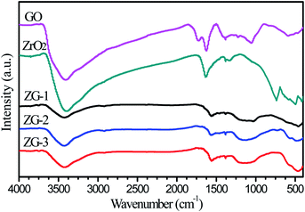
FTIR spectra of the ZrO2-RGO materials prepared by different methods, as well as the original components ZrO2 and RGO, are shown in Fig. 1 below. All of the samples have similar characteristic peaks. The broad absorption peak at 3407 cm−1 in the spectrum of GO is attributed to the O–H stretch of H2O, which indicates that oxide groups exist in GO and H2O molecules can adsorb to these oxide groups. The band at 1717 cm−1 is assigned to the C![[double bond, length as m-dash]](https://www.rsc.org/images/entities/char_e001.gif) O stretch in carbonyl groups which may be found on the edges of GO sheets. Peaks at 1624 cm−1 and 1384 cm−1 are associated with the O–H bending vibrations in H2O and GO, respectively. Peaks at 1225 cm−1 and 1054 cm−1 are identified as the C–O stretches in the carboxyl groups of GO. The absorption peak at 590 cm−1 may be assigned to the asymmetric stretch vibration of the ZrO2 adsorbed on the GO. In the composite materials, the characteristic C
O stretch in carbonyl groups which may be found on the edges of GO sheets. Peaks at 1624 cm−1 and 1384 cm−1 are associated with the O–H bending vibrations in H2O and GO, respectively. Peaks at 1225 cm−1 and 1054 cm−1 are identified as the C–O stretches in the carboxyl groups of GO. The absorption peak at 590 cm−1 may be assigned to the asymmetric stretch vibration of the ZrO2 adsorbed on the GO. In the composite materials, the characteristic C![[double bond, length as m-dash]](https://www.rsc.org/images/entities/char_e001.gif) O peak from the GO disappeared while a new, broader peak is formed near 1160 cm−1, which belongs to C–O–Zr. Another characteristic peak at 1558 cm−1 is observed in the composite materials, which may be related to the C
O peak from the GO disappeared while a new, broader peak is formed near 1160 cm−1, which belongs to C–O–Zr. Another characteristic peak at 1558 cm−1 is observed in the composite materials, which may be related to the C![[double bond, length as m-dash]](https://www.rsc.org/images/entities/char_e001.gif) C bonds formed by sp2-hybridization between adjacent carbon atoms in the lamellar structure of graphene and reduced graphene oxide.23
C bonds formed by sp2-hybridization between adjacent carbon atoms in the lamellar structure of graphene and reduced graphene oxide.23
The samples were further analyzed by BET to determine the properties of the porous structure, which are shown in Table 1 below. The specific surface area of the prepared GO is 721.6 m2 g−1. According to Table 1, ZrO2-RGO composites prepared by the three different methods all exhibit higher specific areas than pure ZrO2. This can be rationalized by a uniform dispersion of ZrO2 particles on the surface and in the pores of RGO. We note that the specific surface area, pore volume, and average pore size of catalysts supported on Cu are slightly smaller compared with the ZrO2-RGO support. This could be caused by the blocking of pores in the ZrO2-RGO by the added Cu particles, which can be seen by XRD.24 Among the five copper containing catalysts, CZG-1 has the largest specific surface area with 143.3 m2 g−1. This indicates that most of the Cu particles are dispersed homogeneously on the surface of the catalyst rather than inside the pores, which would decrease the specific surface area.
| Sample | Specific surface area (m2 g−1) | Pore volume (cm3 g−1) | Average pore size (nm) | D Cu a (nm) |
|---|---|---|---|---|
| a Average crystallite size of metallic copper particles based on XRD pattern. | ||||
| ZG-1 | 150.6 | 0.16 | 3.8 | — |
| ZG-2 | 130.4 | 0.11 | 3.8 | — |
| ZG-3 | 54.5 | 0.25 | 3.9 | — |
| ZrO2 | 38.3 | 0.10 | 3.8 | — |
| GO | 721.6 | 0.91 | 2.2 | — |
| CZG-1 | 143.3 | 0.14 | 3.4 | 13.3 |
| CZG-2 | 129.0 | 0.08 | 3.4 | 7.1 |
| CZG-3 | 50.2 | 0.22 | 3.5 | 11.2 |
| Cu/ZrO2 | 31.4 | 0.05 | 3.4 | 10.8 |
| Cu/RGO | 40.3 | 0.07 | 3.8 | 8.3 |
N2 adsorption–desorption isotherms of ZrO2-RGO composites are shown in Fig. 2a. There are obvious adsorption hysteresis loops in the curves of the materials containing ZrO2. Since the adsorption and desorption isotherms are separated at relatively low pressure (0.4 < P/P0 < 0.8), this indicates that the pore size of the samples is small.25Fig. 2b presents the pore size distributions of the ZrO2-RGO composites, which gives a better understanding of the internal structure of these composite materials. The ZrO2-RGO composites consist mainly of mesopores, with diameters ranging from 2 to 10 nm. Pores in the range of 2–5 nm pores comprise the largest portion of observed pore sizes in the composite material. It is also shown that there are very few pores smaller than 2 nm, known as micropores, in ZG-3, but there are small amounts of micropores observed in ZG-1 and ZG-2. This may be part of the reason why ZG-1 and ZG-2 have larger specific surface areas than ZG-3.
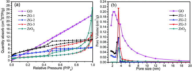 | ||
| Fig. 2 N2 adsorption–desorption isotherms (a) and BJH pore size distributions (b) of ZrO2-RGO composite materials as well as the GO and ZrO2 precursors. | ||
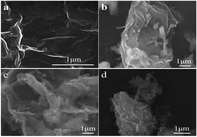
The SEM images of the GO in Fig. 3a reveal typical layered structures, similar to the layered structure of pure graphene in terms of regularity. Fig. 3b–d show the morphological differences of CZG-1, CZG-2, and CZG-3 by SEM. The RGO in CZG-1 appears to have the expected sheet-like structure, but the sheets are stacked together. In CZG-2, the RGO shows a two-dimensional structure, exhibiting a yarn-like sheet, and wrinkles in the two-dimensional layer can be seen. Cu/ZrO2 is uniformly dispersed on the wrinkled layer RGO surface. CZG-3 does not show a two-dimensional layer structure similar to that seen GO. The two-dimensional wrinkles layer structure improves the dispersibility of Cu nanoparticles and effectively prevents the sintering of Cu. The RGO in CZG-1 is stacked, so the dispersibility of Cu cannot be improved, and there is no obvious morphology of RGO in CZG-3 and the catalyst exhibits agglomeration. This indicates that hydrothermally prepared materials have better chemical and physical properties than the other two methods tested. These results will be confirmed by other characterization methods.
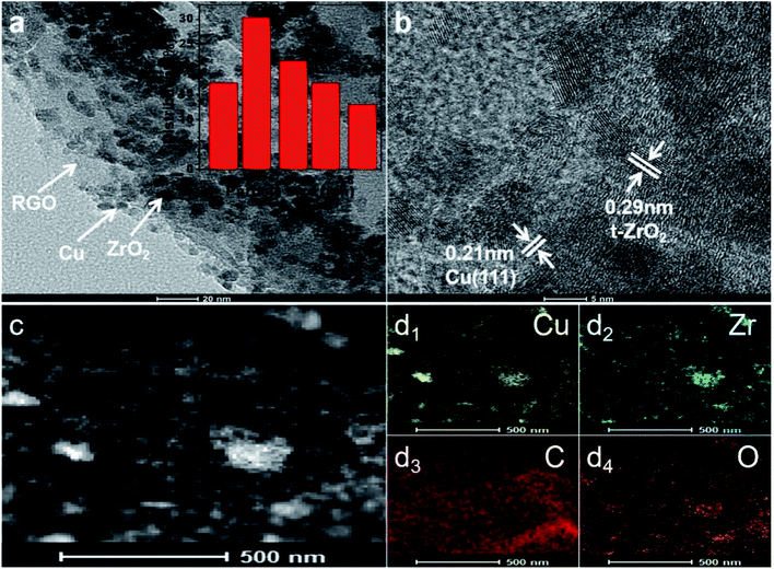
The monodisperse CZG-2 samples were also analyzed by TEM to determine their particle size distribution and structural morphologies. The Cu nanoparticles and ZrO2 are distributed on the pleated layered RGO surface as shown in Fig. 4a. The lattice spacings are 0.21 and 0.29 nm, respectively, corresponding to the crystal plane of Cu (111) and t-ZrO2 in Fig. 4b. Elemental scanning of the catalyst in Fig. 4c and d shows uniform distribution of Cu, Zr, C, and O in the catalyst.
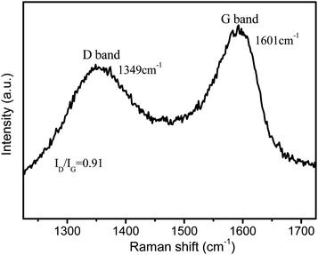
Further analysis with Raman spectroscopy on the CZG-2 sample showed obvious D (breathing mode of sp2-hybridized carbon) and G (graphitic sp2-hybridized carbon) bands, as seen in Fig. 5. Raman spectra verified that the composites also consisted of amorphous carbon, from the G-band and D-band at 1601 and 1349 cm−1, with an intensity ratio of 0.91. The ratio of peak intensities for D and G bands (ID/IG) reflects the extent of defects on graphene materials.
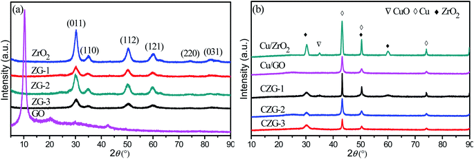
XRD patterns of the composite materials prepared by different methods are shown in Fig. 6a. The peaks in the spectrum of ZrO2 are consistent with the (011), (112), (121), (220), and (031) facets, revealing that the sample has tetragonal symmetry. The characteristic diffraction peak of GO at 2θ of 10° is not observed in the ZrO2-RGO composites. However, there is a weak peak at 2θ of 23.9° in the composites, which belongs to RGO. This shows that GO has been successfully transformed into RGO. The peaks in the ZrO2-RGO composites are similar to the pure ZrO2 sample, but the peaks have smaller intensities and larger full widths at half maximum. According to the Scherrer formula, we know that a larger FWHM leads to smaller crystallite sizes in the composite, compared to the pure ZrO2. It can be seen from the Fig. 6 that ZG-2 has the highest intensity ZrO2 characteristic peak and the largest half slit width in the ZG sample. This shows that the ZG carrier prepared by hydrothermal method has the smallest size.
Fig. 6b presents the XRD patterns of Cu/ZrO2-RGO. Three characteristic diffraction peaks of Cu(111), (200), and (220) at approximately 2θ values of 43.3°, 50.4°, 74.1° can be seen distinctly. There are no peaks from CuO observed in any of the CZG composites. This does not mean that CuO is not present in these materials. CuO may be present, but is in a highly dispersed amorphous state, or are found in smaller crystallites, which may not be able to be detected by XRD. It is also noted that the peaks in Cu/ZrO2-RGO aren't as sharp as the original Cu or ZrO2 samples. This likely occurs because of the strong interactions between the Cu and ZrO2-RGO support. The half-value width of the diffraction peak of Cu in the CZG-2 sample is the largest compared with CZG-1 and CZG-3, indicating that the Cu crystal particles formed are smaller. Because the ZG-2 carrier has a special, wrinkled layer, the interaction between the ZG-2 support and Cu reduces the particle size of the Cu nanoparticles.
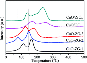
In order to further investigate the interaction between ZrO2-RGO composites and any CuO which may be present in the composite, H2-TPR was performed on the unreduced precursor to the composite catalyst and the results are shown in Fig. 7. Two distinct reduction peaks are observed in the range from 30 °C to 500 °C in all five materials tested, but the peaks occur at different temperatures for each material. This seems to suggest that there are two types of CuO in the composite system. The main reduction peaks at higher temperatures correspond to bulk CuO, whereas the shoulder reduction peaks at lower temperatures are ascribed to well-dispersed CuO on the surface of the catalyst. Notably, the reduction peaks of CuO/ZrO2-RGO composites, observed between 50–200 °C, differ from those of CuO/ZrO2 or CuO/RGO. These differences illustrate that strong interactions between CuO and ZrO2-RGO accelerate the electron transfer between the active component (CuO) and the support (ZrO2-RGO) and enhances the oxidation-reduction ability of the catalyst.26 Preliminary conclusions suggest that the hydrothermal synthesis improves the dispersion of CuO and lowers the catalyst reduction temperature. Combined with SEM, XRD and catalytic performance results, it can be seen that the surface of CZG-2 catalyst sample uniformly disperses Cu nanoparticles with smaller particle size, which can improve the performance and stability of the catalyst.
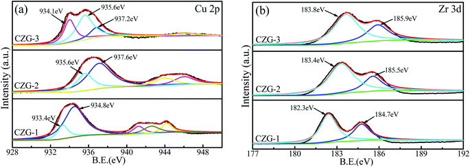
XPS was used to investigate the surface electronic states of Cu and Zr in the different Cu/ZrO2-RGO catalysts. Fig. 8a shows the XPS spectrum of Cu 2p in the catalysts. The binding energy of Cu0 observed around 933.4–935.6 eV, and the binding energy of Cu2+ is found between 934.8–937.6 eV. Each catalyst showed a broad satellite peak in the range of 940–948 eV, which represents Cu2+ in the catalyst. The CZG-2 catalyst has the highest satellite peak intensity and it will be shown below that the catalytic activity was also the highest of the three samples. This suggests that Cu2+ is an important component of the catalytic mechanism for the dehydrogenation of diethanolamine. Fig. 8b shows the XPS spectrum of Zr 3d in the catalysts. Peak fitting shows two species of zirconium, representing Zr 3d5/2 and Zr 3d3/2, are present with a gap between the two of about 2.7 eV. The relative intensity ratio of Zr 3d5/2![[thin space (1/6-em)]](https://www.rsc.org/images/entities/char_2009.gif) :
:![[thin space (1/6-em)]](https://www.rsc.org/images/entities/char_2009.gif) Zr 3d3/2 is 1.5,27 demonstrating the presence of ZrO2. The first is at a lower binding energy, 182.3–183.8 eV (denoted as Zr1), and the second is at a higher binding energy, 184.7–185.9 eV (Zr2). In each of the three catalysts, the proportion of Zr1 is larger than Zr2. The Zr1 peaks in the catalyst samples are similar to Zr4+ (182.6 eV) in pure ZrO2, but these peaks are at higher binding energies, especially CZG-3 (183.8 eV) because of more oxygen vacancies at the surface in this sample.28 Zr2, which is at higher binding energies, is more electron attractive and related to partial Zrδ+ site reduction.29
Zr 3d3/2 is 1.5,27 demonstrating the presence of ZrO2. The first is at a lower binding energy, 182.3–183.8 eV (denoted as Zr1), and the second is at a higher binding energy, 184.7–185.9 eV (Zr2). In each of the three catalysts, the proportion of Zr1 is larger than Zr2. The Zr1 peaks in the catalyst samples are similar to Zr4+ (182.6 eV) in pure ZrO2, but these peaks are at higher binding energies, especially CZG-3 (183.8 eV) because of more oxygen vacancies at the surface in this sample.28 Zr2, which is at higher binding energies, is more electron attractive and related to partial Zrδ+ site reduction.29
In order to identify the catalytic activity of the composite materials, the dehydrogenation of diethanolamine (DEA) was performed. For all samples, catalytic experiments are carried out under similar conditions. Potentiometric titration was chosen to analyze the product iminodiacetic acid (IDA) and the conversion ratio of the DEA. The catalyst test results are shown in Table 2.
Through previous studies of the mechanism of DEA dehydrogenation,31 it is known that DEA is adsorbed on surface of the catalyst. Therefore, it is assumed that the larger the amount of reduced Cu particles on the surface of the composite, the better the catalytic properties of the material will be. Interestingly, the catalytic activity improved when GO was added to the catalyst. The experimental results agree with previous literature results. When adding GO into the catalyst, the specific surface area of catalysts increases and the dispersion of the active component, Cu in this study, can be improved. The reducibility of GO can protect Cu from being oxidized in air. For example, CZG-1 and CZG-2 have larger specific surface areas than other composite catalysts, and better activity is also found for these materials. CZG-1 has the largest specific surface area of the composites, but CZG-2 has the best catalytic performance. According to Table 2, the DEA conversion rate of CZG-2 reached 96% and the IDA selectivity reached 92%, respectively. This suggests that specific surface area is not the dominant factor influencing the performance of the DEA dehydrogenation reaction. The interactions between Cu and ZrO2-RGO as well as the pore structure appear to have an important influence on the performance of the catalyst. The porous nature of the composite can help present more active sites which may lead to stronger interactions between Cu and the ZrO2-RGO support and better catalytic activity of the composite material. Comparing the sample CZG-2 with the commercially produced RANEY® Cu, the reaction time was greatly shortened, and the reaction time was the fastest and the reuse rate was higher than other catalysts in the literature, such as CZ@CN30 and Cu–Cr.3
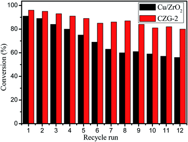
Catalyst reusability is often a problem because of material instability and leaching of the active sites from the catalyst. Therefore, a reusability experiment was performed to test these composite catalysts. The CZG-2 catalyst was chosen, as it had the best performance of the composite materials for repeated experiments. After each cycle, the catalyst was washed to remove any reaction solution still interacting with the catalyst, followed by drying at 50 °C for 12 hours. A total of 12 cycles were performed, each using the filtered catalyst from the previous run. Fig. 9 shows the reusability of the catalysts. After 8 catalytic cycles with CZG-2, DEA conversion rate remains above 90%, and the conversion rate decreases slowly until the 12th iteration, where the conversion rate of DEA is still above 80%. These results show that the CZG-2 catalyst has good stability. It is noted that the color of the reaction solution gradually changes from colorless to blue, with increasing cycle repetition. The presence of Cu in the reaction solution was detected by inductively coupled plasma (ICP). This shows that Cu leaches from the composite catalyst during the reaction process. The leaching of Cu is correlated with the reduction of the catalyst activity. Further testing is needed to determine if this Cu leaching is in fact the cause of the catalyst deactivation.
It is generally believed that the catalytic mechanism of catalytic dehydrogenation of diethanolamine, to produce iminodiacetic acid, is similar to the catalytic dehydrogenation of monoethanolamine, to produce glycine.32 This suggests that diethanolamine acts as a sub-catalyst under the Cu-based catalyst. Two molecules of aldehyde are converted to sodium iminodiacetic acid in a strong base environment. In the Cu/ZrO2-RGO catalysts, the hydroxyl group on diethanolamine interacts with the Cu-based catalyst basic sites to capture protons, thus forming an alkoxide intermediate with the Cu species. Alkaline solutions have been shown to accelerate the rate of deprotonation.33 The alkoxide intermediate is adsorbed on the Cu active sites, and then another active proton is removed by α-H cleavage during catalysis by Cu, eventually forming an aldehyde. The reaction process for preparing an ester from an aldehyde may proceed through two reaction routes: (1) the two aldehyde molecules undergo the Cannizzaro reaction or (2) the aldehyde and the alcohol undergo a nucleophilic addition reaction. However, the observed ester cannot be obtained by the first route when an α-H is present in the aldehyde, as the α-H will be removed by the base in the reaction to produce aldol condensation. Therefore, the ester formation reaction does not proceed through the Cannizzaro route. The second route proceeds as follows: the base captures the α-H on the intermediate aldehyde, thus causing the electrophilic α-C to appear, thus having a nucleophilic addition. The active alkoxide reacts to form an ester, which is decomposed in an alkaline environment to give the iminodiacetic acid salt.34
Experimental
Materials
Natural graphite (NG) with an average particle size of 125 μm, CAS 7782-42-5 was obtained from Aladdin. Zirconium oxynitrate hydrate (ZrO(NO3)2·5H2O), 99.5% purity, was obtained from Shanghai Macklin of China. Cupric nitrate (Cu(NO3·3H2O)) and sodium hydroxide (NaOH) powder were supplied by Tianjin Chemical Industry Co. Ltd., China. Hydrochloric acid (HCl) 36%–38%, and sulfuric acid (H2SO4) 98%, were obtained from Hengyang Chemical Industry Co. Ltd., China. Diethanolamine (A.R. > 99.0%) was provided by Tianjin Hengxing Chemical Industry of China. 25% Ammonia solution (NH3·H2O), CAS1336-21-6, and citric acid powder (C6H8O7), CAS77-92-9, were from Hengyang Kaixin Chemical Industry Co. Ltd., China. All chemical reagents are analytical grade, and ultrapure water was used throughout the experiments.Catalyst characterizations
FEI Tecnai G2 F20 transmission electron microscope (TEM, FEI); SU8200 field emission scanning electron microscope (SEM, Hitachi, Japan); TriStar II 3020 specific surface area and aperture analyzer (BET, McMuratick Instrument Co., LTD., USA); AutoChem II 2920 (H2-TPR McMuratick Instrument Co., LTD., USA); NICOLET 380 Fourier infrared spectrometer (FTIR, Niccoli, USA); Dmax-2500/PC X-ray polycrystalline powder diffuser (XRD, Kishi Corporation, Japan); model 1200 high performance liquid chromatography (Agilent, USA).Preparation of graphene oxide (GO)
Graphene oxide (GO) was synthesized from NG flakes using Hummers' method.35 The prepared graphene oxide was uniformly dispersed in water using ultrasonication,36 to obtain a solution of 1 g L−1 concentration. The dispersed solution was used as-prepared for further experiments.Preparation of ZrO2-RGO by co-precipitation
200 mL of a 0.1 M ZrO(NO3)2·5H2O solution was slowly added to 300 mL of the dispersed GO solution. The solution was stirred rapidly for 1 h at room temperature. Then, ammonia was added as the precipitating agent, until the pH of the mixture reached approximately 11. The solution was then heated at 70 °C for 4 h. The deposits were washed with water, until the pH of the resulting solution was found to be 7. The solution and precipitate were held at 60 °C for about 12 h in order to remove the solvent and fully dry the precipitate. Finally, the product, denoted as ZG-1, was fabricated by hot pressing using a tubular furnace under a nitrogen atmosphere at 450 °C for 3 h.Preparation of ZrO2-RGO by hydrothermal synthesis
The ZrO2-RGO solution is the same as used in the co-precipitation method, but a different precipitating agent was chosen. 0.5 M NaOH was added slowly to the ZrO2-RGO solution until the solution was pH 9. The solution was transferred to a hydrothermal reactor with a Teflon-lined autoclave at 170 °C for 12 h. After repeated washing with distilled water, the product, denoted as ZG-2, was heated for an additional 12 h at 60 °C to remove all solvent.Preparation of ZrO2-RGO sol–gel
The ZrO2-RGO solution was prepared as in the other two synthetic methods. 200 mL of a 1 M citric acid solution was slowly pumped into the ZrO2-RGO solution over 1 h with stirring. After 30 min of additional stirring, ammonia was added dropwise to the mixture until the solution reached pH 5. The solution was heated in a water bath at 80 °C for 4 h. The resulting product, denoted as ZG-3, was dried in air and calcined under nitrogen at 400 °C for 3 h.Preparation of Cu/ZrO2-RGO
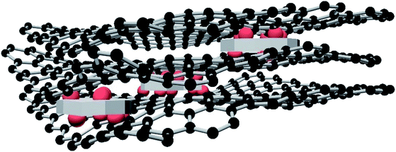
The three ZrO2-RGO products, ZG-1, ZG-2, and ZG-3, (6.44 g) were each mixed separately with Cu(NO3)2·3H2O (4.84 g) and ground together using a ball mill. Cu/ZrO2-RGO composites, independently named as CZG-1, CZG-2, CZG-3, were prepared by calcination under nitrogen at 450 °C for 3 h and hydrogen reduction at 250 °C for 4 h. To highlight the importance of the structure and composition of CZG, the corresponding ZrO2, Cu/ZrO2, and Cu/RGO materials were made and compared to the composite materials. The preparation procedure for the ZrO2, Cu/ZrO2, and Cu/RGO materials can be found in the ESI.† The schematic diagram of Cu/ZrO2-RGO catalyst is shown in Fig. 10.Catalytic evaluation
Cu/ZrO2-RGO was used as a catalyst for the dehydrogenation of diethanolamine. Diethanolamine and sodium hydroxide (1![[thin space (1/6-em)]](https://www.rsc.org/images/entities/char_2009.gif) :
:![[thin space (1/6-em)]](https://www.rsc.org/images/entities/char_2009.gif) 2.5 mol
2.5 mol![[thin space (1/6-em)]](https://www.rsc.org/images/entities/char_2009.gif) :
:![[thin space (1/6-em)]](https://www.rsc.org/images/entities/char_2009.gif) mol) were reacted with 4.5 g catalyst at 160 °C for 4 h. The content of sodium iminodiacetic acid (DSIDA) in the reaction solution was analyzed by high-performance liquid chromatography (HPLC).
mol) were reacted with 4.5 g catalyst at 160 °C for 4 h. The content of sodium iminodiacetic acid (DSIDA) in the reaction solution was analyzed by high-performance liquid chromatography (HPLC).
Conclusions
In this paper, ZrO2-RGO composite carriers successfully incorporated copper-based catalysts in order to obtain high catalytic dehydrogenation activity, good stability, and good dispersibility. The ZrO2-RGO composite carriers prepared by hydrothermal, sol–gel, and coprecipitation methods were used as a raw material to synthesize Cu/ZrO2-RGO catalysts. RGO with a folded layer structure was introduced as the second carrier for the catalyst to improve the dispersion and sintering resistance of the catalyst. The performance of the Cu/ZrO2-RGO catalyst prepared by hydrothermal synthesis of ZrO2-RGO carrier is best compared with the commercial RANEY® Cu or the literature,3,29 and the reaction time is the shortest. This is because Cu and ZrO2 are uniformly distributed on the surface of the pleated, layered RGO, and the Cu nanoparticles have higher dispersibility. This provides a new method for the preparation of copper-based catalysts with excellent dispersibility and sintering resistance. Catalyst cycling tests show that the CZG-2 catalyst can still dehydrogenate diethanolamine after 12 cycles of reaction. The conversion to IDA is still 80% after the 12th cycle, indicating that the hydrothermally prepared ZrO2-RGO carrier can prevent the sintering and agglomeration of Cu nanoparticles and improve the stability of the catalyst. The Cannizzaro reaction in the dehydrogenation of diethanolamine to prepare sodium iminodiacetic acid was negated, and the nucleophilic addition reaction of aldehyde and alcohol was proposed for the reaction mechanism. However, the leaching problem of Cu in the catalyst needs further study in order to improve the cycling lifetime of the catalyst.Conflicts of interest
There are no conflicts of interest to declare.Acknowledgements
This work was supported by the National Natural Science Foundation of China (21576229).Notes and references
- G. H. Lu, X. M. Hua, J. Cheng, Y. L. Zhu, G. H. Wang, Y. J. Pang, R. W. Yang, L. Zhang, H. Shou, X. M. Wang, J. Qi and Y. H. Yang, Curr. Genomics, 2018, 19, 36–49 CAS.
- Y. Zhu, X. Kong, X. Li, G. Ding, Y. Zhu and Y. W. Li, ACS Catal., 2014, 4, 3612–3620 CrossRef CAS.
- D. A. Hickman, K. Mosner and J. W. Ringer, Chem. Eng. J., 2015, 278, 447–453 CrossRef CAS.
- Z. Liu, R. Che, A. A. Elzatahry and D. Zhao, ACS Nano, 2014, 8, 10455–10460 CrossRef CAS PubMed.
- Z. K. Duan, S. Li, F. Xie, J. H. Yan and T. Zhang, Chem. Res. Appl., 2015, 27, 417–423 CAS.
- K. Samson, M. Śliwa, R. P. Socha, K. Góra-Marek, D. Mucha, D. Rutkowska-Zbik, J. F. Paul, M. Ruggiero-Mikołajczyk, R. Grabowski and J. Słoczyńsk, ACS Catal., 2016, 4, 3730–3741 CrossRef.
- P. Y. Chen and A. Alù, ACS Nano, 2011, 5, 5855–5863 CrossRef CAS.
- A. C. Neto and A. Geim, New Sci., 2012, 214, iv–v CrossRef.
- J. Hwang, T. Yoon, S. H. Jin, J. Lee, T. S. Kim, S. H. Hong and S. Jeon, Adv. Mater., 2013, 25, 6724–6729 CrossRef CAS.
- A. M. Dimiev and J. M. Tour, ACS Nano, 2014, 8, 3060–3068 CrossRef CAS.
- A. Malas and C. K. Das, Composites, Part B, 2015, 79, 639–648 CrossRef CAS.
- X. Cai, Y. Luo, B. Liu and H. M. Cheng, Chem. Soc. Rev., 2018, 47, 6224–6266 RSC.
- M. Kumar, Z. Gholamvand, A. Morrissey, K. Nolan, M. Ulbricht and J. Lawler, J. Membr. Sci., 2016, 506, 38–49 CrossRef CAS.
- M. Rashid, P. K. Mondal, S. Q. Usmani and S. Sabir, Journal of Industrial Research & Technology, 2013, 3, 72–76 Search PubMed.
- E. Rokhsat and O. Akhavan, Appl. Surf. Sci., 2016, 371, 590–595 CrossRef CAS.
- H. Yang, J. Jiang, W. Zhou, L. Lei, L. Xi, Y. M. Lam, Z. Shen, B. Khezri and T. Yu, Nanoscale Res. Lett., 2011, 6, 531–538 CrossRef.
- Y. Mithilesh, R. Y. Kyong, S. J. Park and D. Hui, Composites, Part B, 2014, 66, 89–96 CrossRef.
- X. Huang, K. Shi, J. Yang, G. Mao and J. Chen, J. Power Sources, 2017, 356, 72–79 CrossRef CAS.
- T. Demirci, B. Çelik, Y. Yıldız, S. Eriş, M. Arslan, F. Sen and B. Kilbas, RSC Adv., 2016, 80, 76948–76956 RSC.
- G. Haydar, Y. Yıldız, B. Çelik, M. Yazıcı, B. Kilbas and F. Sen, ChemistrySelect, 2016, 1, 953–958 CrossRef.
- G. Haydar, Y. Yıldız, B. Çelik, M. Yazıcı, B. Kilbas and F. Sen, Catal. Sci. Technol., 2016, 6, 2318–2324 RSC.
- B. Şen, E. H. Akdere, A. Şavk, E. Gültekin, Ö. Paralı, H. Göksu and F. Şen, Appl. Catal., B, 2018, 225, 148–153 CrossRef.
- K. Krishnamoorthy, M. Veerapandian, K. Yun and S. J. Kim, Carbon, 2013, 53, 38–49 CrossRef CAS.
- Y. Q. Song, D. H. He and B. Q. Xu, Appl. Catal., A, 2008, 337, 19–28 CrossRef CAS.
- X. M. Liu, H. X. Xue, X. Li and Z. F. Yan, Catal. Today, 2010, 158, 446–451 CrossRef CAS.
- L. C. Wang, Q. Liu, M. Chen, Y. M. Liu, Y. Cao, H. Y. He and K. N. Fan, J. Phys. Chem. C, 2007, 111, 16549–16557 CrossRef CAS.
- J. Wan, P. Yang, X. L. Guo and R. X. Zhou, Chin. J. Catal., 2019, 40, 1100–1108 CrossRef CAS.
- A. G. Sato, D. P. Volanti, D. M. Meira, S. Damyanova and J. M. C. Bueno, J. Catal., 2013, 307, 1–17 CrossRef CAS.
- S. Ardizzone and C. L. Bianchi, Surf. Interface Anal., 2015, 30, 77–80 CrossRef.
- Y. Wang, Y. Zhao, Z. Zhao, X. Lan, J. Xu, W. Xu and Z. Duan, Acta Chim. Sin., 2019, 71, 661–668 CrossRef.
- G. Carotenuto, R. Tesser, M. D. Serio and E. Santacesaria, Catal. Today, 2013, 203, 202–210 CrossRef CAS.
- Y. Yang, Z. Duan and W. Liu, Chem. React. Eng. Technol., 2001, 17, 210–215 CAS.
- E. Balaraman, E. Khaskin, G. Leitus and D. Milstein, Nat. Chem., 2013, 5, 122–125 CrossRef CAS.
- M. Neurock, Z. Tao, A. Chemburkar, D. D. Hibbitts and E. Lglesia, Faraday Discuss., 2017, 197, 59–86 RSC.
- D. C. Marcano, D. V. Kosynkin, J. M. Berlin, A. Sinitskill, Z. Sun, A. Slesarev, L. B. Alemany, W. Lu and J. M. Tour, ACS Nano, 2010, 4, 4806–4814 CrossRef CAS.
- Y. Liu, H. V. Babu, J. Zhao, A. Goñi-Urtiaga, R. Sainz, R. Ferritto, M. Pita and D. Wang, Composites, Part B, 2016, 89, 108–116 CrossRef.
Footnote |
| † Electronic supplementary information (ESI) available. See DOI: 10.1039/c9ra05458h |
| This journal is © The Royal Society of Chemistry 2019 |

