
 Open Access Article
 This Open Access Article is licensed under a Creative Commons Attribution-Non Commercial 3.0 Unported Licence
Core–shell ZnO:Ga-SiO2 nanocrystals: limiting particle agglomeration and increasing luminescence via surface defect passivation
Lenka Procházková *ab,
Vojtěch Vaněčeka,
Václav Čubaa,
Radek Pjatkanc,
Rosana Martinez-Turtosd,
Ivo Jakubece,
Maksym Buryib,
Sergey Omelkovf,
Etiennette Auffrayg,
Paul Lecoqg,
Eva Mihókováab and
Martin Niklb
*ab,
Vojtěch Vaněčeka,
Václav Čubaa,
Radek Pjatkanc,
Rosana Martinez-Turtosd,
Ivo Jakubece,
Maksym Buryib,
Sergey Omelkovf,
Etiennette Auffrayg,
Paul Lecoqg,
Eva Mihókováab and
Martin Niklb
aCzech Technical University in Prague, Faculty of Nuclear Sciences and Physical Engineering, Břehová 7, 115 19 Czech Republic. E-mail: lenka.prochazkova@fjfi.cvut.cz
bInstitute of Physics of the AS CR, v.v.i, Cukrovarnická 10, Prague 6, Czech Republic
cNUVIA a.s., Trojanova street 117, 278 01 Kralupy nad Vltavou, Czech Reublic
dUniversità degli Studi di Milano Bicocca, Piazza della Scienza 3, 20126, Milano, Italy
eInstitute of Inorganic Chemistry of the Czech Academy of Sciences, Řež 250 68, Husinec-Řež 1001, Czech Republic
fInstitute of Physics, University of Tartu, W. Ostwaldi 1, 50411 Tartu, Estonia
gCERN, 1211 Geneva 23, Switzerland
First published on 17th September 2019
Abstract
Heat treatment is needed to increase the luminescence intensity of ZnO:Ga particles, but it comes at the cost of higher particle agglomeration. Higher agglomeration results in low transparency of scintillating powder when embedded in a matrix and constitutes one of the biggest disadvantages, besides low light yield and low stopping power, of ZnO:Ga powder. Limiting ZnO:Ga particle size is therefore a key step in order to prepare highly luminescent and transparent composites with prospects for optical applications. In this work, SiO2 coating was successfully used to improve luminescence intensity or limitation of crystallite size growth during further annealing. Furthermore, ZnO:Ga and ZnO:Ga-SiO2 core–shells were embedded in a polystyrene matrix.
Introduction
ZnO:Ga3+ is a well-known scintillator with extremely fast emission in the UV spectral region, wide band gap (3.4 eV), relatively high exciton binding energy EB (60 meV), low afterglow and especially extremely short luminescence decay of excitons (sub-ns)1 with practically zero rise time.2 While there are many different methods for preparation of luminescent ZnO nanocrystals,3–6 the materials prepared via photo-induced methods seem to feature the most favourable fast timing characteristics.1 Subsequent heat treatment of photo induced nanocrystals under specific conditions7 provides high-quality scintillators with strong exciton-related emission and without any defect-related emission in visible spectral range.1 However, it comes at the cost of increased particle size. For practical use in most applications, the nanopowder needs to be embedded in a suitable optically transparent matrix, but increased particle size results in low transparency of fabricated composite. This feature, alongside the low light yield and low stopping power of ZnO:Ga powder represents one of the biggest disadvantages of ZnO-based luminescent composites. To limit the ZnO:Ga particle size is therefore a key step in the preparation of highly luminescent and transparent ZnO:Ga composites applicable for the next-generation scintillators used in high energy physics (HEP) and time of flight positron emission tomography (TOF-PET).8It is known that the luminescence intensity in nanocrystals of direct gap semicondcutors can be strongly reduced due to the surface defects (vacancies, non-saturated bonds or adsorbed species) acting as charge carrier traps and nonradiative recombination centers and various strategies have been adopted to suppress them.9–11 Their negative effect can be healed by frequently used surface passivation12,13 effectively implemented as a shell formed around the active core. Resulting core–shell systems are currently investigated and exploited in a number of applications. Core–shell quantum dots (QDs) based on CdSe core and a variety of shells are already applied in light emitting diodes for monitors and TV screens14–18 or photovoltaics.19,20 Together with Cd-free QDs they are also studied for biomedical applications.12,21
Shell layer can serve many purposes depending on the nature of the material and its desired characteristics. The shell can protect the core material from environment, improve its poor mechanical properties or alter its optical properties.22 Recently, various methods have been studied for passivation or modification of the nanoparticle (NP) surface, depending on the target application.23,24 The surface coverage by either organic polymers or inorganic (amorphous, semi-crystalline or crystalline) layers was implemented. Properly chosen and applied outer layer in core–shell materials can limit the particle agglomeration which occurs during annealing at higher temperatures25 and/or improve their optical properties, such as the light yield or decay time.26 One can grow an inorganic solid shell on the core via a sol–gel route, cover the core by organic ligands or grow a polymer shell by a polymerization process to make the core biocompatible.27
Sol–gel route to synthesize ZnO@SiO2 core–shell systems has already been reported.28 Alternatively, hydrothermally-prepared ZnO cores were coated by SiO2 and then selectively etched by the aqueous solution of HCl.29 Scanning electron microscope (SEM) images and energy-dispersive spectra (EDS) clearly showed hollow SiO2 shells and confirmed successful synthesis of the ZnO@SiO2 core–shell composites. A deposition of SiO2 layer on ZnO nanowires via reactive sputtering to passivate native point defects was used.12 The passivation of oxygen vacancies resulted in strong suppression of the visible emission and the effect of annealing at higher temperatures (700-900 °C) was also studied.
The coating of ZnO nanorods by Al2O3 and hydrogen plasma treatment were investigated to passivate the surface states associated with the deep-level emission in the green spectral area.13 Coating by MgO was tested,30 however the overall intensity of emission decreased with increasing MgO layer thickness above 15 nm. Selected optoelectronic properties may be improved by the adsorption of organic layer on the ZnO nanoparticles.31 Thus, the wavelength selectivity and UV absorbance was significantly improved by the adsorption of DMF on the ZnO NPs surface. To stabilize colloidal particles, organic surfactants or polymers may be used, e.g. polymer thin shell has been synthesized on the ZnO nanoparticle surface from pre-existing inherent free radicals.32
Recently, high attention has been devoted to the preparation of thin films on substrates or composite materials where scintillating nanopowders and nanoparticles are immobilized in the optically transparent matrices. There are several works reporting on the luminescent properties of ZnO embedded into more or less transparent organic materials and a wide range of polymers was investigated.33–35 However, polystyrene (PS) matrix currently seems to be the most promising due to its convenient luminescence properties.2,36 Specifically, the PS matrix itself is an efficient scintillator and moreover, an energy transfer from the matrix to the scintillating ZnO crystals is possible.36 ZnO:Ga-polystyrene composites (ZnO:Ga-PS) were prepared and already reported in Burešová et al., 2016,36 where 10 wt% filling with powder was used; characterization of the composite showed that low transparency does not allow sufficient transmission of emitted light.
For an actual design of optical devices based on nanoparticles embedded in host matrices, two key problems need to be solved; increasing the intensity of radioluminescence to sufficient level comparable with single crystals or optical ceramics and limiting the growth of nanoparticles, so that they can be embedded in sufficient amount without decreasing the optical transparency of the matrix.
In this work, we study the surface defect passivation and limiting growth of luminescent ZnO:Ga particles by SiO2 coating and embedding in polystyrene (PS) matrix together with the effect of these procedures on luminescence properties. We also compare ZnO:Ga-PS with core–shell ZnO:Ga-SiO2-PS at various levels of filling.
Experimental
(A) Methods
Heat treatment of samples was carried out in a vacuum furnace 0415 VAK (Clasic s. r. o.) with the regulator Clare 4.0 enabling to set up the temperature, time of calcination and temperature gradient. LABSYS EVO was used for heat treatment of products in reducing atmosphere of Ar/H2 (10![[thin space (1/6-em)]](https://www.rsc.org/images/entities/char_2009.gif) :1).
:1).
X-ray powder diffraction (XRPD) was used for structural and phase analysis. XRPD was performed using Rigaku MiniFlex 600 (Ni-filtered Cu-Kα 1,2 radiation) equipped with NaI:Tl scintillation detector and diffractograms were compared to the relevant records in the ICDD PDF-2 database (version 2013). Determination of the specific surface area of the samples by single point BET method was carried out on Monosorb MS-22 (Quantachrome Instruments) using the mixture containing 30% of nitrogen and 70% of helium as a carrier gas. Further characterization was performed using scanning electron microscopy (SEM, Philips XL30CP) high resolution transmission electron microscopy (HRTEM, JEOL 3010), and selected area electron diffraction (SAED). Luminescence properties were evaluated by measuring photoluminescence (PL) steady-state and time-resolved spectra as well as the radioluminescence (RL) spectra using the custom-made spectrofluorometer 5000 M, Horiba JobinYvon. X-ray tube (RL spectra) and nanoLED 339 nm (PL decays) were used as the excitation sources. Detection part of the set-up consisted of single grating monochromator and photon counting detector TBX-04. Time-correlated single photon counting technique was utilized to measure subnanosecond PL decays and measured spectra were corrected for the spectral dependence of detection sensitivity. PL decays were determined by convolution procedure (SpectraSolve software package, Ames Photonics). RL decay measurements were performed in time correlated single photon counting using a pulsed tungsten X-ray tube and a fast hybrid PMT from Becker & Hickl with a FWHM of around 55 ps. Photons are integrated over the entire spectral range from 220–800 nm with no further discrimination. The impulse response function of the whole setup (laser + X-ray tube + photodetector + electronic readout) has been obtained by means of intraband luminescence present in Li2MoO4 crystals with a final FWHM of around 130 ps. For more details, please refer to ref. 37.
(B) Preparation of ZnO:Ga core
Luminescent ZnO:Ga3+ nanopowder was prepared via photo-induced precipitation, as described in Procházková et al., 2015.1 Solid phase after UV irradiation was dried, annealed at 200 °C and either used as it were or further annealed at 1000 °C in air and 800 °C in the mixture of Ar/H2.(C) Amorphous SiO2 shell
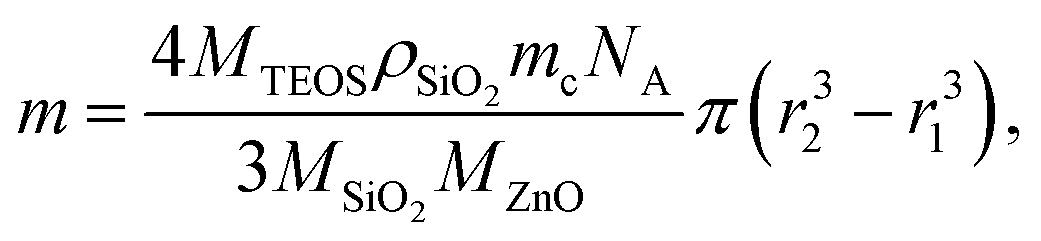
Amorphous silica coating of ZnO:Ga nanopowder was applied on powder (i) annealed at 200 °C to investigate the particle agglomeration during further treatment of core–shells, or (ii) treated in air at 1000 °C and in Ar/H2 at 800 °C to investigate the effect on luminescence properties. Alkaline hydrolysis of tetraethyl orthosilicate (TEOS) by aqueous solution of ammonium hydroxide is used for SiO2 coating. The powder is dried at 150 °C in vacuum for 30 min and then dispersed in absolute ethanol. The amount of TEOS needed for coating was calculated so as to cover the particle of average diameter 1 µm by the shell of the theoretical thickness of 25, 50 and 100 nm. Theoretical thickness is only an approximation. Diameter of the ZnO:Ga core was determined using specific surface area measurements. Assuming complete hydrolysis of TEOS and formation of continuous SiO2 shell with constant thickness on spherical ZnO:Ga cores amount m of TEOS is given by formula:
 | (1) |
The superstoichiometric amount of ammonium hydroxide was added dropwise and the suspension was stirred for 5 hours to ensure the complete hydrolysis of TEOS. Product was washed by ethanol and water, separated and dried.
In particle agglomeration study, the SiO2 coated ZnO:Ga nanopowder processed according to (i) was subsequently annealed at 400 °C, 600 °C and 1000 °C and the effect on the crystallinity, particle size and phase purity was investigated. RL spectra were measured for ZnO:Ga-SiO2 core–shells where annealed powder was used as a core material.
(D) ZnO:Ga embedding in PS matrix
The amounts 0.5 g or 5 g of ZnO:Ga powder were mixed with 50 g of granulated polystyrene (Synthos PS GP 171) in Brabender lab mixer to prepare the composite with 1 or 10 wt% filling. The mixture was subsequently press compacted in stainless steel frame, which was placed between the pairs of glass and stainless steel slabs, into the 1 mm thick plate. Smaller pieces of composite samples were prepared via dissolving of pre-polymerized granulate of PS in toluene and admixture of ZnO:Ga, ZnO:Ga-SiO2 (1, 5 and 10 wt% filling was tested).Results and discussion
(A) Limiting the particle agglomeration by SiO2 layer
ZnO:Ga particles were coated by amorphous SiO2 layer and heat treated at various temperatures. Average linear crystallite size calculated from XRPD by the Halder–Wagner method data is 13 nm and it does not significantly change up to 600 °C. At 1000 °C, both the particle size and linear crystallite size increase up to ∼1 µm. HRTEM images confirm the estimated crystallite size and clearly show an appearance of agglomerates due to the coalescence of particles at the temperatures higher than 600 °C, accompanied by the formation of zinc silicate crystalline phase (see Fig. 1, ZnO:Ga-SiO2 1000 °C, and Fig. 2).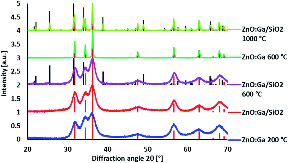 | ||
| Fig. 1 XRPD diffractograms of ZnO:Ga and ZnO:Ga-SiO2 heat treated at various temperatures. Diffraction lines of ZnO PDF database record #00-036-1451 given by red dashed lines, Zn2SiO4 PDF database record #00-037-1485 given by black dashed lines. | ||
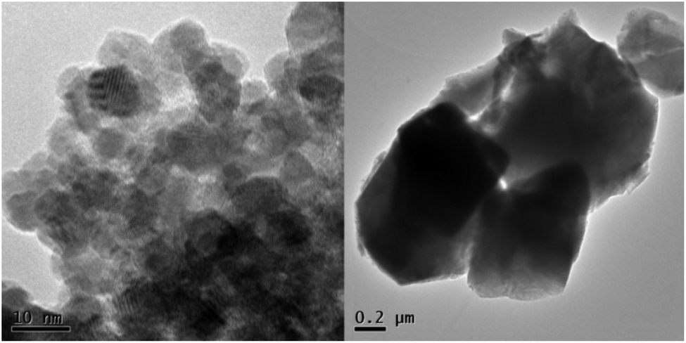 | ||
| Fig. 2 HRTEM images of ZnO:Ga-SiO2 without further heat treatment (left) and after treatment at 1000 °C (right). | ||
(B) Improving the luminescence intensity
Improving luminescence properties via surface passivation was investigated on ZnO:Ga particles heat treated in air at 1000 °C and subsequently in H2/Ar at 800 °C. Coating by SiO2 via alkaline hydrolysis lead to the formation of amorphous SiO2 layer without any other crystalline phase, as confirmed by XRPD measurements (Fig. 3).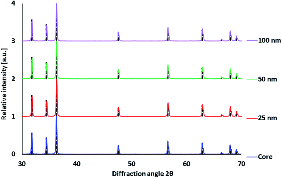 | ||
| Fig. 3 XRPD diffractograms of ZnO:Ga-SiO2 (ZnO:Ga annealed at 1000 °C before coating) with different SiO2 theoretical thickness. Diffraction lines of ZnO PDF database record #00-036-1451 given by black dashed lines. | ||
The morphology of ZnO:Ga-SiO2 core–shells was investigated using SEM, HRTEM and EDX. SEM images with EDX show spherical particles of varying size and lower Zn concentration (Fig. 4). TEM images prove that hexagonal zinc oxide crystals occur in the centre of spherical formations in many cases (Fig. 5), but also pure amorphous SiO2 particles are formed. This unwanted effect is likely to be suppressed by the optimization of TEOS concentration and kinetics of the SiO2 layer growth.
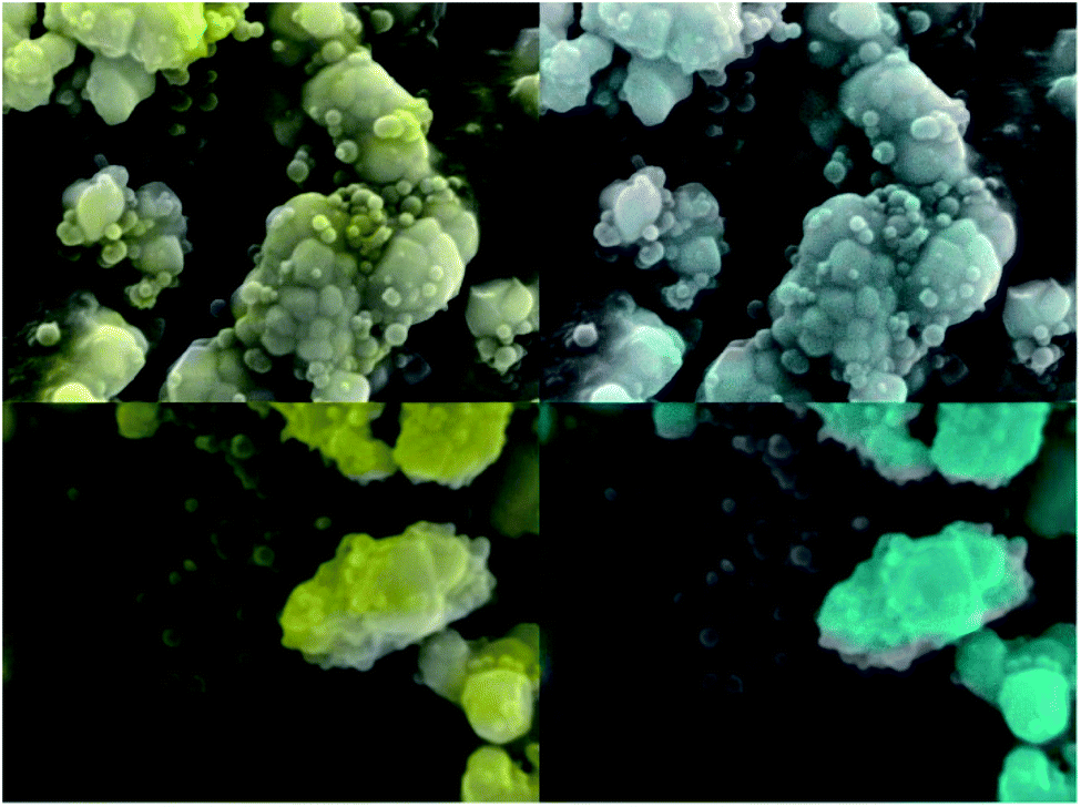 | ||
| Fig. 4 SEM images of ZnO:Ga-SiO2 particles with EDX element analysis. Turquoise colour represents zinc, yellow colour represents silicon. | ||
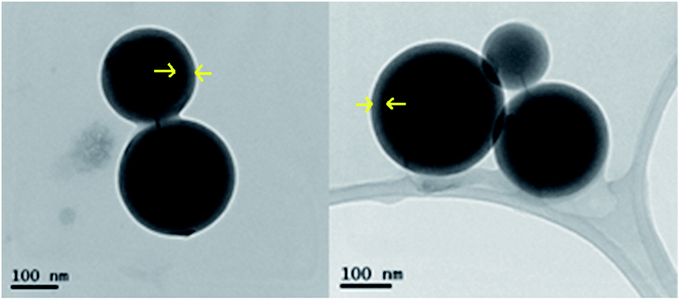 | ||
| Fig. 5 HRTEM images of ZnO:Ga-SiO2 core–shells. Arrows denote thickness of SiO2 shell. | ||
RL spectra of ZnO:Ga-SiO2 core–shells feature significantly increased intensity of the emission with maxima at 390 nm in comparison with pure ZnO:Ga particles (Fig. 6). We assume, that homogeneous SiO2 shell on the surface of ZnO:Ga scintillating core heals the surface defects, thus contributing to the increase of RL intensity. Improving luminescence intensity may be explained by the healing of the surface defects and passivation of surface states, as mentioned in ref. 31 and 32. In Fu et al., 201138 the authors propose that the reduction in trap density within the band gap causing preferred radiative recombination near the band edge is due to the passivation of dangling bonds and O2− ions on the surface. Moreover, Sombrio et al.12 suggest the improving of ZnO/SiO2 interface due to the Zn–O–Si bond formation above certain temperature as a possible explanation.
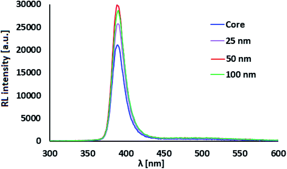 | ||
| Fig. 6 RL spectra of ZnO:Ga-SiO2 with different SiO2 theoretical thickness. | ||
(C) PS matrix
Following the optimization discussed in Section B, ZnO-based nanopowders were embedded in PS host matrix: highly luminescent ZnO:Ga particles, and ZnO:Ga@SiO2 core–shells with improved luminescence intensity. The ZnO:Ga-PS and ZnO:Ga-SiO2-PS composite samples with 1 wt% filling are shown in Fig. 7. RL spectra in Fig. 8A show both the UV emission from PS between 300–350 nm and exciton-related emission from ZnO:Ga particles peaking at 390 nm. It is obvious that 1 wt% filling is not sufficient to complete the transfer of the excitation energy absorbed by polystyrene matrix to the ZnO:Ga particles. Increasing the amount of scintillating powder obviously leads to the increase in the opacity of composites. In case of ZnO:Ga-SiO2, the enhancement of RL intensity peaking at 390 nm is observed in comparison with the ZnO:Ga-PS sample (see Fig. 8B).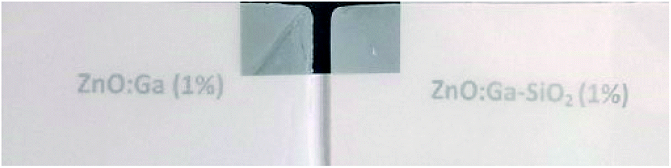 | ||
| Fig. 7 Images of 1 mm thick ZnO:Ga-PS composite plates (1 wt% filling). | ||
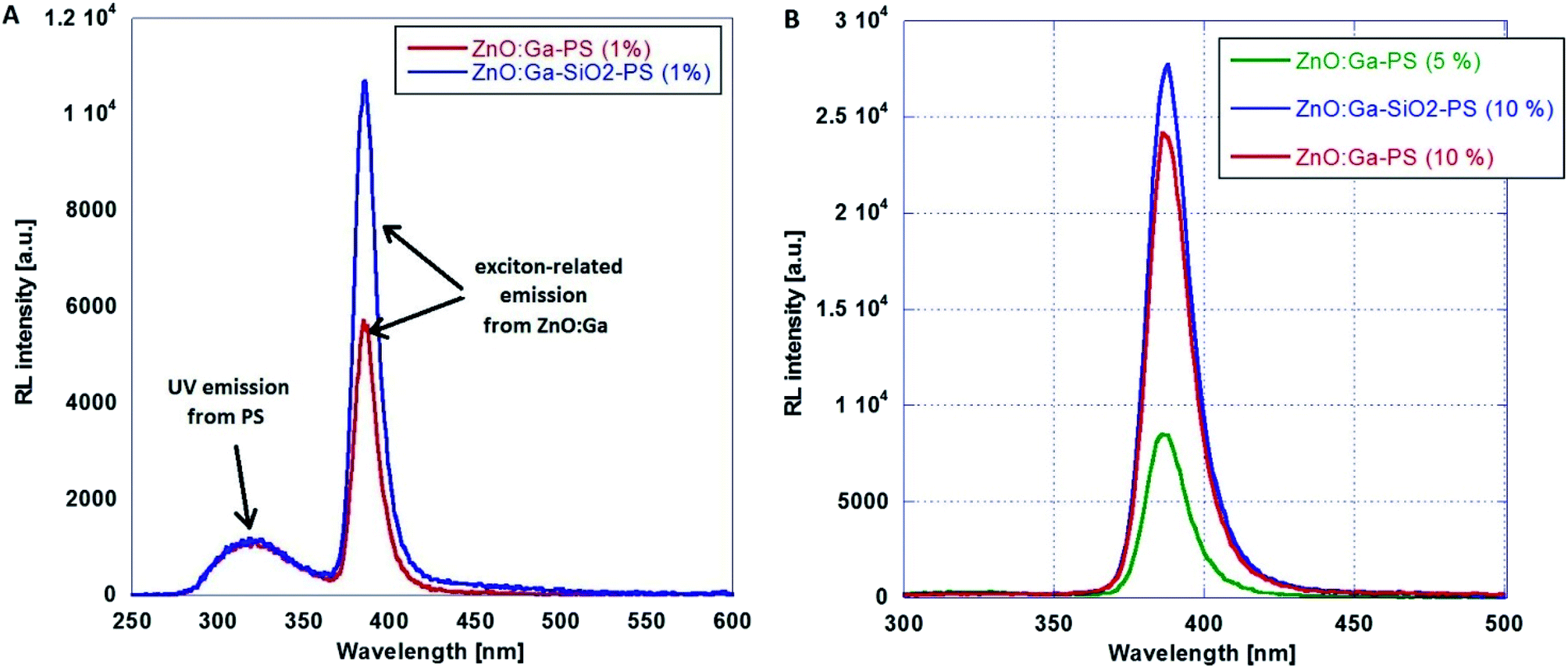 | ||
| Fig. 8 RL spectra of ZnO:Ga-PS (1 wt%) and ZnO:Ga-SiO2-PS (1 wt%) composites (A) and composites with 5 wt% and 10 wt% filling (B). | ||
A series of photoluminescence decays as well as spectral-time resolved measurements using X-ray excitation source were performed. We expect that PS matrix is primarily excited under 281 nm, while ZnO:Ga particles are directly excited under 339 nm. Photoluminescence decays are shown in Fig. 9A and B. Minor slow component is noticeable under both 281 and 339 excitation wavelengths. In the case of the excitation of PS matrix, slow component (13.6 ns) may origin in the emission of PS itself. Direct excitation of ZnO:Ga particles features slow component about 4 ns, probably caused by capture of exciton on the interface of ZnO:Ga particles and PS matrix. Spectrally integrated data obtained by pulsed X-ray excitation for ZnO:Ga-PS and ZnO:Ga-SiO2-PS are shown in Fig. 10A and B. It is obvious that silica layer does not negatively affect timing performance and extremely short decay with practically zero rise time preserved. The decays do not show any presence of polystyrene host emission as already reported in ref. 2 and 36. The absence of PS slower emission in X-ray decays may be explained by transfer of energy absorbed by PS to ZnO particles. Values of several hundreds of picoseconds in PL and X-ray excited decays of fast excitonic ZnO or ZnO:Ga emission were also reported in literature. X-ray excited luminescence decays at RT of ZnO:Ga powders showed two components – 320 and 820 ps in ref. 42, 800 ps in ref. 7, ZnO nanowires treated through hydrogen plasma demonstrated faster decays from 300 to 140 ps at 10 K,43 PL decay time of free exciton in ZnO single crystal of 400 ps was observed at RT in ref. 44 and the value of about 1 ns is reported for ZnO:Ga ceramics.45
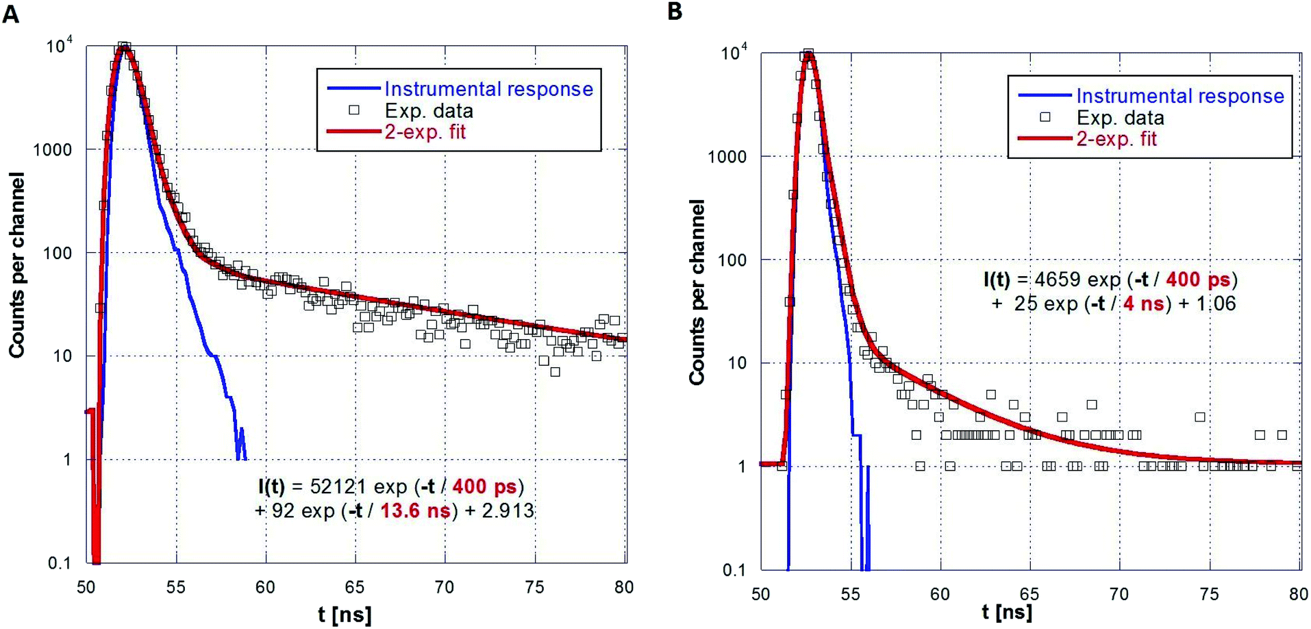 | ||
| Fig. 9 PL decays of ZnO:Ga-PS (5 wt%) under 281 nm (A) and 339 nm (B) excitation and two-exponential fits. | ||
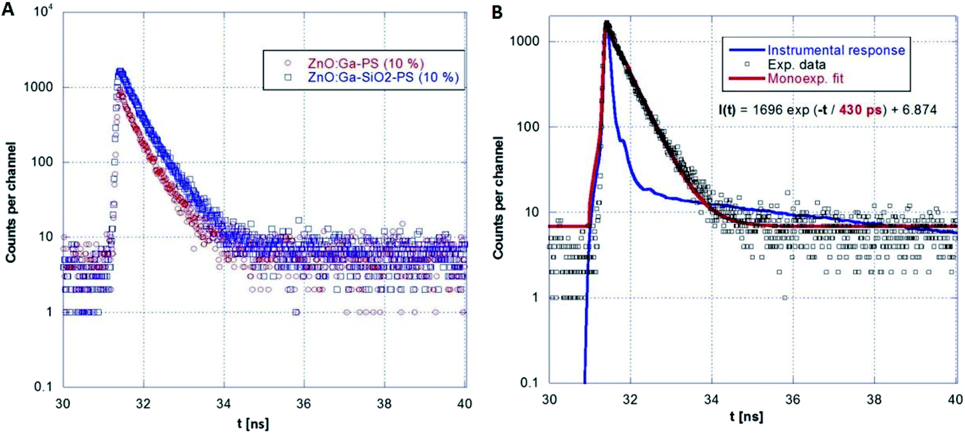 | ||
| Fig. 10 Comparison of ZnO:Ga-PS (10 wt%) and ZnO:Ga-SiO2-PS (10 wt%) RL decays (A) and single-exponential fit for ZnO:Ga-SiO2-PS (10 wt%) sample (B). | ||
Conclusions
SiO2 amorphous shell applied on ZnO:Ga particles treated at 200 °C may be used to limit both the crystallite and particle sizes during further heat treatment up to 600 °C.Covering ZnO:Ga scintillating particles by amorphous SiO2 layer via sol–gel process significantly improves the luminescence intensity due to the passivation of the particle surface defects.
Composites prepared by embedding ZnO:Ga-based particles in polystyrene with sufficient powder filling (∼10 wt%) show only strong UV emission from ZnO:Ga particles, but the low transparency limits their practical use. Composites with very low filling (1 wt%) exhibit also the emission from the PS matrix, while the 5 wt% filling is already sufficient to ensure an effective transfer of absorbed energy from the matrix to ZnO:Ga particles. Extremely short PL and RL decays between 200–700 ps with practically zero rise time were preserved. Slow component associated with PS is present only in the case of 1 wt% filling.
Presented results show methods for particle size limitation and surface passivation via silica covering and embedding in polymer matrix. These steps play a key role in the further development of scintillating nanomaterials for detectors. However, microstructural study of composite core–shell scintillators is an ongoing task.
Despite some disadvantages, synthesized ZnO:Ga-based scintillators show a strong promise for applications in future generation of detectors as well as photo/radiotherapy.39–41 ZnO:Ga-PS composites with appropriate composition have a high potential for use in fast-timing applications. Nevertheless, some improvements are needed. Even though annealing temperatures of the ZnO:Ga core are rather high, in possible future applications, annealing of large amounts of the material may reduce the cost. Despite that, lowering the annealing temperature is a high priority in future research, since it would also limit the particle agglomeration.
Conflicts of interest
There are no conflicts to declare.Acknowledgements
Financial support of the Czech Science Foundation under Grant No. GA 17-06479S, the Ministry of Education Youth and Sports, project “Center for advanced applied science,” No. CZ.02.1.01/0.0/0.0/16_019/0000778, Estonian Research Council (PUT1081) and European Regional Development Fund (Estonian Centre of Excellence TK141, project No. 2014-2020.4.01.15-0011) as well as a partial support from Operational Programme Research, Development and Education financed by European Structural and Investment Funds and the Czech Ministry of Education, Youth and Sports (Project No. SOLID21 CZ.02.1.01/0.0/0.0/16_019/0000760) are gratefully acknowledged.The study was carried out in the frame of Crystal Clear collaboration and received support from ERC grant no. 338953 TICAL, the EC H2020 project no. 690599 ASCIMAT and COST Action TD1401 (FAST).
References
- L. Procházková, T. Gbur, V. Čuba, V. Jarý and M. Nikl, Opt. Mater., 2015, 47, 67–71 CrossRef.
- R. M. Turtos, S. Gundacker, M. T. Lucchini, L. Procházková, V. Čuba, H. Burešová, J. Mrázek, M. Nikl, P. Lecoq and E. Auffray, Phys. Status Solidi RRL, 2016, 10(11), 843–847 CrossRef CAS.
- S. Ilican, Y. Caglar and M. Caglar, J. Optoelectron. Adv. Mater., 2008, 10(10), 2578–2583 CAS.
- I.-S. Kim, S.-H. Jeong and B.-T. Lee, Semicond. Sci. Technol., 2007, 22, 683–686 CrossRef CAS.
- J. Nause and B. Nemeth, Semicond. Sci. Technol., 2005, 20, 45–48 CrossRef.
- J. Wang and L. Gao, Solid State Commun., 2004, 132, 269–271 CrossRef CAS.
- E. D. Bourret-Courchesne, S. E. Derenzo and M. J. Weber, Nucl. Instrum. Methods Phys. Res., Sect. A, 2009, 601, 358–363 CrossRef CAS.
- C. Dujardin, E. Auffray, E. Bourret, P. Dorenbos, P. Lecoq, M. Nikl, A. N. Vasil'ev, A. Yoshikawa and R. Zhu, IEEE Trans. Nucl. Sci., 2018, 65, 1977–1997 CAS.
- C. Bullen and P. Mulvaney, Langmuir, 2006, 22(7), 3007–3013 CrossRef CAS PubMed.
- G. Xiong, U. Pal and J. G. Serrano, J. Appl. Phys., 2007, 101(2), 024317 CrossRef.
- G. H. Ahmed, J. K. El-Demellawi, J. Yin, J. Pan, D. B. Velusamy, M. N. Hedhili, E. Alarousu, O. M. Bakr, H. N. Alshareef and O. F. Mohammed, ACS Energy Lett., 2018, 3(10), 2301–2307 CrossRef CAS.
- C. I. L. Sombrio, P. L. Frazen, R. dos Reis, H. I. Boudinov and D. I. Baptista, Mater. Lett., 2014, 134, 126–129 CrossRef CAS.
- C. Chen, H. He, Y. Lu, K. Wu and Z. Ye, ACS Appl. Mater. Interfaces, 2013, 5(13), 5889–6442 CrossRef PubMed.
- E. Jang, S. Jun, H. Jang, J. Lim, B. Kim and Y. Kim, Adv. Mater., 2010, 22, 3076–3080 CrossRef CAS PubMed.
- T.-H. Kim, S. Jun, K.-S. Cho, B. L. Choi and E. Jang, MRS Bull., 2013, 38, 712–720 CrossRef CAS.
- D. V. Talapin and J. Steckel, MRS Bull., 2013, 38, 685–691 CrossRef CAS.
- G. J. Supran, Y. Shirasaki, K. W. Song, J.-M. Caruge, P. T. Kazlas, S. Coe-Sullivan, T. L. Andrew, M. G. Bawendi and V. Bulovicć, MRS Bull., 2013, 38, 703–711 CrossRef.
- J. S. Steckel, J. Ho and S. Coe-Sullivan, Photonics Spectra, 2014, 48, 55–61 Search PubMed.
- W. U. Huynh, W. W. Dittmer and A. P. Alivisatos, Science, 2002, 295, 2425–2427 CrossRef CAS PubMed.
- E. Arici, D. Meissner, F. Schäffler and N. Serdar Sariciftci, Int. J. Photoenergy, 2003, 5, 199–208 CrossRef CAS.
- J. M. Klostranec and W. C. W. Chan, Adv. Mater., 2006, 8(15), 1953–1964 CrossRef.
- G. Xu, S. Zeng, B. Zhang, M. T. Swihart, K. T. Yong and P. N. Prasad, Chem. Rev., 2016, 116(19), 12234–12327 CrossRef CAS PubMed.
- N. O. V. Plank, H. J. Snaith, C. Ducati, J. S. Bendall, L. Schmidt-Mende and M. E. Welland, Nanotechnology, 2008, 19, 465603 CrossRef CAS PubMed.
- D. Kong, P. Yang, Z. Wang, P. Chai, S. Huang, H. Lian and J. Lin, J. Nanomater., 2008, 2008, 312792 Search PubMed.
- A. E. Raevskaya, Y. V. Panasiuk, O. L. Stroyuk, S. Y. Kuchmiy, V. M. Dzhagan, A. G. Milekhin, N. A. Yeryukov, L. A. Sveshnikova, E. E. Rodyakina, V. F. Plyusnin and D. R. T. Zahn, RSC Adv., 2014, 4, 63393 RSC.
- O. Chen, J. Zhao, V. P. Chauhan, J. Cui, C. Wong, D. K. Harris, H. Wei, H.-S. Han, D. Fukumura, R. K. Jain and M. G. Bawendi, Nat. Mater., 2013, 12, 445–451 CrossRef CAS PubMed.
- N. A. Alcantar, E. S. Aydil and J. N. Israelachvili, J. Biomed. Mater. Res., 2000, 51, 343–351 CrossRef CAS PubMed.
- Q. Liu, Z. Xu, J. A. Finch and R. Egerton, Chem. Mater., 1998, 10(12), 3936–3940 CrossRef CAS.
- F. Li, X. Huang, Y. Jiang, L. Liu and Z. Li, Mater. Res. Bull., 2009, 44, 437–441 CrossRef CAS.
- Z. Shi, Y. Zhang, X. Cui, S. Zhuang, B. Wu, X. Chu, X. Dong, B. Zhang and G. Duab, Phys. Chem. Chem. Phys., 2015, 17(21), 13813–13820 RSC.
- A. M. Bazargan, F. Sharif, S. Mazinani and N. Naderi, J. Mater. Sci.: Mater. Electron., 2016, 27, 8221–8226 CrossRef CAS.
- H. M. Xiong, Z. D. Wang and Y. Y. Xia, Adv. Mater., 2006, 18, 748–751 CrossRef CAS.
- R. Li, G. R. Fern, R. Withnall, J. Silver, P. Bishop and B. Thiebaut, MRS Proceedings, 2013, 1509 CrossRef CAS , mrsf12-1509-cc03-17.
- T. Gbur, M. Vlk, V. Čuba, A. Beitlerová and M. Nikl, Radiat. Meas., 2013, 56, 102–106 CrossRef CAS.
- J. J. Huang, Y. B. Ye, Z. Q. Lei, X. J. Ye, M. Z. Rong and M. Q. Zhang, Phys. Chem. Chem. Phys., 2014, 16(12), 5480–5484 RSC.
- H. Burešová, L. Procházková, R. M. Turtos, V. Jarý, E. Mihóková, A. Beitlerová, R. Pjatkan, S. Gundacker, E. Auffray, P. Lecoq, M. Nikl and V. Čuba, Opt. Express, 2016, 24(14), 15289–15298 CrossRef PubMed.
- R. M. Turtos, S. Gundacker, S. Omelkov, E. Auffray and P. Lecoq, J. Lumin., 2019, 215, 116613 CrossRef CAS.
- M. Fu, Y. Li, S. Wu, P. Lu, J. Liu and F. Dong, Appl. Surf. Sci., 2011, 258, 1587–1591 CrossRef CAS.
- Y. Zhang, W. Chen, S. Wang, Y. Liu and C. Pope, J. Biomed. Nanotechnol., 2008, 4, 432–438 CrossRef CAS.
- Y. Liu, Y. Zhang, S. Wang, C. Pope and W. Chen, Appl. Phys. Lett., 2008, 92(1–3), 143901 CrossRef.
- L. Procházková, I. T. Pelikánová, E. Mihóková, R. Dědic and V. Čuba, Radiat. Meas., 2019, 121, 13–17 CrossRef.
- S. E. Derenzo, et al., Nucl. Instrum. Methods Phys. Res., Sect. A, 2002, 486, 214–219 CrossRef CAS.
- J. Yoo, et al., J. Lumin., 2016, 176, 278–282 CrossRef CAS.
- J. Wilkinson, K. B. Ucer and R. T. Williams, Picosecond excitonic luminescence in ZnO and other wide-gap semiconductors, Radiat. Meas., 2004, 38, 501–505 CrossRef CAS.
- V. A. Demidenko, E. I. Gorokhova, I. V. Khodyuk, O. A. Khristich, S. B. Mikhrin and P. A. Rodnyi, Scintillation properties of ceramics based on zinc oxide, Radiat. Meas., 2007, 42(4–5), 549–552 CrossRef CAS.
| This journal is © The Royal Society of Chemistry 2019 |