 Open Access Article
In situ autologous growth of self-supporting NiFe-based nanosheets on nickel foam as an efficient electrocatalyst for the oxygen evolution reaction†
Jianying Wanga,
Xue Tenga,
Yanli Niua,
Lixia Guoa,
Jianfei Kongb,
Xiaoming He a and
Zuofeng Chen
 *ac
*ac
aShanghai Key Lab of Chemical Assessment and Sustainability, School of Chemical Science and Engineering, Tongji University, Shanghai 200092, China. E-mail: zfchen@tongji.edu.cn
bJiangsu Vocational College of Medicine, Yancheng 224005, Jiangsu Province, China
cCollege of Chemistry and Materials Science, Longyan University, Longyan, Fujian 364012, China
First published on 12th July 2019
Abstract
A highly efficient and low-cost oxygen evolution reaction electrocatalyst is essential for water splitting. Herein, a simple and cost-effective autologous growth method is developed to prepare NiFe-based integrated electrodes for water oxidation. In this method, a Ni(OH)2 nanosheet film is first developed on nickel foam by oxidative deposition in a chemical bath solution. The as-prepared nanosheet electrode is then immersed into a solution containing Fe(III) cations to form an Fe-doped Ni(OH)2 electrode by utilization of the different solubility of metal cations. Benefiting from its unique and integrated nanostructure, this hierarchically structured electrode displays extremely high catalytic activity toward water oxidation. In 1 M KOH, the electrode can deliver a current density of 1000 mA cm−2 at an overpotential of only 330 mV. This work provides a facile way to produce an efficient, durable, and Earth-abundant OER electrocatalyst with no energy input, which is attractive for large-scale water splitting.
Introduction
Water splitting to produce hydrogen fuels represents one of the most appealing strategies to obtain clean and sustainable energy.1,2 The water splitting reaction can be classified into two half cell reactions: the hydrogen evolution reaction (HER) and the oxygen evolution reaction (OER).3,4 As one of the half reactions, OER has more sluggish kinetics and requires higher overpotentials than the relatively simple HER, since it involves the removal of 4e− and 4H+ from two water molecules to generate one oxygen molecule.5 As a result, the large overpotential of the OER greatly increases the overall energy input of the water splitting.6 To reduce the overpotential loss of the OER, the development of cost-effective, high-performance OER electrocatalysts is urgently required.Over the past decade, extensive efforts have been devoted to develop OER catalysts based on the first-row transition non-precious metals.7–10 Among these Earth-abundant materials, nickel-iron-based electrocatalysts have attracted much attention owing to their high OER activity.11–13 It has now been well-established that incorporation of Fe into Ni composite can significantly enhance the catalytic activity for water oxidation, since the conductivity and charge transfer of NiFe-based electrocatalyst can be dramatically increased by taking the advantage of synergistic metal–metal interactions.14–16 In earlier studies, these catalyst materials are usually prepared by electrodeposition or hydrothermal reaction methods followed by casting onto the electrode substrate surface.17–21 These strategies however may result in several problems, such as high energy input during the catalyst preparation, slow charge transfer between catalyst and electrode substrate and poor stability under vigorous O2 evolution conditions.22–24
To overcome these obstacles, some integrated electrodes prepared by in situ self-growth method were reported recently.22–26 For example, Cao et al. reported an integrated NiFe-based electrode by a surface oxidation method, and Zheng et al. developed a combinatorial self-regulated acidic etching and topotactic selenization method for preparation of electrocatalysts.22,26 Recently, the Chen group and the Zou group reported respectively NiFe-based integrated electrodes by the spontaneous galvanic replacement reaction with an iron foam in Ni(II) solution, which show excellent catalytic activity for OER.23,24 These in situ self-growth strategies can simplify the fabrication procedures, lower the production costs and enhance catalytic activities and stabilities of NiFe-based electrocatalysts.
Herein, we report a NiFe-based OER electrocatalyst prepared by oxidative deposition of nickel foam in a chemical bath solution followed by an ion-exchange treatment. The fabrication procedure is simple and cost-effective without complex instrumentation, predesigned templates and extraneous nickel source. The fabrication process of the NiFe-based electrode materials for water oxidation is illustrated in Scheme 1. A NiFe-based electrocatalyst film with uniform nanosheets was formed on the nickel foam surface. The integrated electrode exhibits a hierarchical structure with large specific surface area and high catalytic activity and durability toward OER in alkaline media. In 1 M KOH, the electrode can deliver a very high current density of 1000 mA cm−2 at an overpotential of only 330 mV.
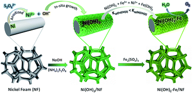 | ||
| Scheme 1 Fabrication process of the Ni(OH)2–Fe electrodes and their utilization for water oxidation. | ||
Experimental
Materials
Ferric sulfate (Fe2(SO4)3, 98%), potassium hydroxide (KOH, 99%), sodium hydroxide (NaOH, 99%), ammonium persulfate ((NH4)2S2O8, 98%); hydrochloric acid (HCl) and ethanol (C2H5OH, 99.8%) were obtained from Sigma Aldrich. Nickel foam (NF, thickness ∼0.5 mm, bulk density ∼0.56 g cm−3) was obtained from Shanxi Lizhiyuan Material of Battery Co. Ltd (China). All other reagents were analytical grade and used as received. All electrolyte solutions were prepared with deionized water (18 MΩ cm) unless stated otherwise.Preparation of Ni(OH)2–Fe/NF electrodes
The nickel foam (1 × 3 cm2) was firstly cleaned by ultrasonication in 1 M HCl solution for 2 h to remove the organic impurities and oxides on the surface, and then cleaned in ethanol (5 min) and deionized water (5 min) in sequence by ultrasonication, respectively. The nickel foam was stored in a glass bottle for 24 h at room temperature. Then, the nickel foam was taken out and immersed in mixed solution of (NH4)2S2O8 (5 mL, 1 M) and KOH (10 mL, 3 M) in a 20 mL transparent bottle for 8 h under the ambient temperature. The resultant electrode was washed with deionized water thoroughly and named as Ni(OH)2/NF electrode. The as-prepared Ni(OH)2/NF electrode was then placed in a solution containing 20 mM Fe2(SO4)3 aqueous solution. The Ni(OH)2/NF electrode had an exposure geometric surface area of 2 cm2 in the solution. The reaction between Fe(III) and Ni(OH)2 was processed under the ambient temperature. The resultant electrode was washed with deionized water thoroughly and named as Ni(OH)2–Fe/NF electrode.Characterizations
Scanning electron microscope (SEM) images, energy dispersive X-ray spectroscopy analysis (EDX) data and EDX mapping images were obtained at Hitachi S-4800 (Hitachi, Japan) equipped with a Horiba EDX system. Transmission electron microscopy (TEM) images, high resolution TEM (HRTEM) images and selected area electron diffraction (SAED) image were obtained using JEM-2100, JEOL. The NiFe-based nanosheets catalyst was removed from the Ni(OH)2–Fe/NF electrode substrate by sonication in the absolute ethanol, and a drop of the mixture was dried on a the micro grid copper network for analysis. Powder X-ray diffraction (XRD) was measured by Bruker D8 Focus via ceramic monochromatized Cu Kα radiation of 1.54178 Å, operating at 40 kV and 40 mA. Raman spectra were recorded on a confocal microscope laser Raman spectrometer (Reinshaw invia). X-ray photoelectron spectroscopy (XPS) for elemental analysis was conducted on a Kratos Axis Ultra DLD X-ray Photoelectron Spectrometer using 60 W monochromated Mg Kα radiation as the X-ray source for excitation. The carbon 1s peak (284.6 eV) was used for internal calibration. The peak resolution and fitting were processed by XPS Peak 41 software.Electrochemical measurements
Electrochemical measurements were performed on a CHI 660E electrochemical workstation (Chenhua Corp., Shanghai, China). The three-electrode system consisted of a working electrode, a platinum plate counter electrode, and a saturated calomel reference electrode (SCE, ∼0.244 V vs. NHE). Unless stated otherwise, all potentials in cyclic voltammetry were reported vs. RHE with 80% iR compensation and all controlled potential electrolysis and chronopotentiometry experiments were conducted without iR compensation. All experiments were performed at 22 ± 2 °C.Results and discussion
Characterizations of Ni(OH)2–Fe/NF electrodes
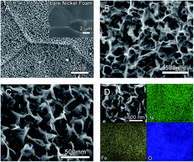
As illustrated in Scheme 1, the Ni(OH)2 nanosheet electrode is firstly prepared by oxidation of a fresh nickel foam in a mixed solution containing (NH4)2S2O8 and NaOH. In the second step, the as-prepared Ni(OH)2 nanosheet electrode is immersed into a solution containing Fe(III) ions for different times at room temperature. Due to the different water solubility of Ni(OH)2 and Fe(OH)3 (Ksp(Fe(OH)3) = 2.6 × 10−39 < Ksp(Ni(OH)2) = 5.0 × 10⁻¹⁶), parts of Ni(II) in Ni(OH)2 nanosheets are replaced by Fe(III) in the solution, which forms the Fe-doped Ni(OH)2 nanosheet electrodes.The morphology of the as-prepared electrodes was firstly investigated by scanning electron microscopy (SEM). Fig. 1A and B show that a uniform film of Ni(OH)2 nanosheets is formed on the electrode substrate after the oxidative deposition treatment. After immersion in 20 mM Fe(III) solution for 5 min, Fig. 1C displays that the resultant Ni(OH)2–Fe/NF electrode maintains the uniform morphology of nanosheet structure. The SEM images of the Ni(OH)2–Fe/NF electrodes prepared by different immersion times are also provided. As shown in Fig. S1,† the nanosheet structure of the electrode is destroyed after immersion in Fe(III) solution for a prolonged time of 10 min, indicating an important effect of the immersion time on the structure of the prepared electrode. The SEM-energy dispersive X-ray spectroscopy (EDX) measurement was conducted to probe the elemental composition and distribution in the Ni(OH)2–Fe/NF electrode. In Fig. S2,† the elemental analysis reveals that the nanosheet material is composed of Ni, Fe and O elements. Moreover, the elemental mapping images show that these elements are distributed uniformly within the nanosheets, as shown in Fig. 1D.
To further investigate the morphology structure of the Ni(OH)2–Fe/NF electrode, the transmission electron microscopy (TEM) test was also conducted. As shown in Fig. S3,† the nanosheet structure could be clearly observed. The selected-area electron diffraction (SAED) pattern in Fig. S3A† inset indicates the amorphous or low-crystallinity structure of the nanosheet material. Accordingly, the high-resolution TEM (HRTEM) image in Fig. S3B† also presents the amorphous structure with no visible lattice fringes in the nanosheet, consistent with the SAED pattern.
The bulk crystallity and surface composition of the hierarchical electrodes were characterized by X-ray diffraction (XRD). In Fig. S4,† the XRD patterns of the Ni(OH)2/NF and Ni(OH)2–Fe/NF electrodes exhibit three diffraction peaks located at 44.5°, 51.8°, and 76.4°, respectively, which can be assigned to the (111), (200) and (220) planes of cubic Ni (PDF# 04-0850).17 No other diffraction peaks are observed in the XRD patterns, indicating the amorphous or low-crystallinity structure of the both Ni(OH)2 and Ni(OH)2–Fe nanosheet materials, which is consistent with TEM results.17
Fig. 2A shows Raman spectra of the Ni(OH)2/NF and Ni(OH)2–Fe/NF electrodes. As the electrode background, no Raman signal is detected for the bare nickel foam. At the Ni(OH)2/NF electrode, the Raman spectrum exhibits a pair of broad peaks located at 469 and 543 cm−1, which are attributed to Ni–O vibrations in NiOOH.14–16 At the Ni(OH)2–Fe/NF electrode, these two peaks shift to 477 and 552 cm−1, which is consistent with the incorporation of the Fe3+ cations into the Ni(OH)2 nanosheets.14–16
Fig. S5† shows the survey X-ray photoelectron spectroscopy (XPS) of the Ni(OH)2–Fe/NF electrode, revealing the Fe, Ni and O elements on the electrode surface with an atomic ratio of ∼2![[thin space (1/6-em)]](https://www.rsc.org/images/entities/char_2009.gif) :
:![[thin space (1/6-em)]](https://www.rsc.org/images/entities/char_2009.gif) 1 for Ni
1 for Ni![[thin space (1/6-em)]](https://www.rsc.org/images/entities/char_2009.gif) :
:![[thin space (1/6-em)]](https://www.rsc.org/images/entities/char_2009.gif) Fe. Fig. 2B–D show the high-resolution XPS of Ni 2p, Fe 2p, and O 1s, respectively. In Ni 2p XPS, two dominant peaks are observed at binding energies of 855.5 and 873.1 eV for Ni 2p1/2 and Ni 2p3/2, which are accompanied by two less intense satellite peaks, consistent with the presence of divalent Ni.12,24 In Fe 2p XPS, two dominant peaks are located at 710.9 and 725.0 eV, indicating the presence of trivalent Fe.22,27,28 The high-resolution XPS of O 1s exhibits the existence of three oxygen contributions, which are denoted as O1, O2, and O3, respectively. Specifically, the fitting peak of O1 at 529.7 eV is typical of metal–oxygen bonds.27,29,30 The O2 located at 531.1 eV is usually associated with oxygen in hydroxyl groups.27,29,30 The O3 appeared at 532.6 eV can be assigned to oxygen species in the surface-adsorbed H2O molecule.24,27 All the analysis results indicate that the NiFe co-doping double-hydroxide material has been successfully prepared.
Fe. Fig. 2B–D show the high-resolution XPS of Ni 2p, Fe 2p, and O 1s, respectively. In Ni 2p XPS, two dominant peaks are observed at binding energies of 855.5 and 873.1 eV for Ni 2p1/2 and Ni 2p3/2, which are accompanied by two less intense satellite peaks, consistent with the presence of divalent Ni.12,24 In Fe 2p XPS, two dominant peaks are located at 710.9 and 725.0 eV, indicating the presence of trivalent Fe.22,27,28 The high-resolution XPS of O 1s exhibits the existence of three oxygen contributions, which are denoted as O1, O2, and O3, respectively. Specifically, the fitting peak of O1 at 529.7 eV is typical of metal–oxygen bonds.27,29,30 The O2 located at 531.1 eV is usually associated with oxygen in hydroxyl groups.27,29,30 The O3 appeared at 532.6 eV can be assigned to oxygen species in the surface-adsorbed H2O molecule.24,27 All the analysis results indicate that the NiFe co-doping double-hydroxide material has been successfully prepared.
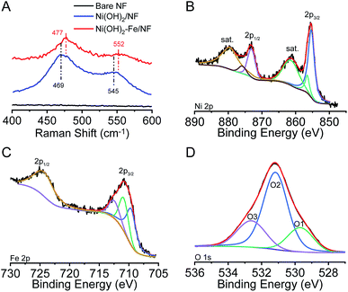 | ||
| Fig. 2 (A) Raman spectra of the bare nickel foam, Ni(OH)2/NF and Ni(OH)2–Fe/NF electrodes. The high-resolution XPS of Ni 2p (B), Fe 2p (C) and O 1s (D) of the Ni(OH)2–Fe/NF electrode. | ||
Electrocatalytic OER performance
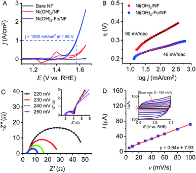
The electrocatalytic activity of the electrodes toward water oxidation were evaluated in a typical three-electrode setup in 1.0 M KOH with Pt-plate as the counter electrode and saturated calomel electrode as the reference electrode. Fig. 3A shows cyclic voltammetry (CV) plots of the bare nickel foam, Ni(OH)2/NF and Ni(OH)2–Fe/NF electrodes toward water oxidation. Obviously, in comparison with bare NF and Ni(OH)2/NF electrodes, the Ni(OH)2–Fe/NF electrode displays a significantly enhanced OER catalytic activity with an onset overpotential of 210 mV and an overpotential of 330 mV to deliver an extremely large current density of 1000 mA cm−2. This excellent OER performance with large catalytic current density at small overpotential outperforms most reported state-of-the-art OER electrocatalysts, as shown in Table 1. It is noting that CVs of the Ni(OH)2/NF and Ni(OH)2–Fe/NF electrodes feature an apparent prewave before the catalytic OER onset, consistent with conversion of divalent Ni to trivalent Ni. The decreased intensity of this prewave and the enhanced catalytic activity of the Ni(OH)2–Fe/NF electrode indicates that the Fe-doped Ni(OH)2 nanosheet electrode has been successfully fabricated by this strategy. The catalytic activities of the Ni(OH)2–Fe/NF electrodes prepared by varying the immersion time are shown in Fig. S6.† The catalytic current density increases rapidly at the initial time, and then decreases by further extending the immersion time. With an optimized immersion time of 5 min, it reaches the maximum value. In contrast, the redox prewave is decreased monotonously along with the immersion time. These observations are consistent with the transformation of Ni(OH)2 to Fe(OH)3 on the electrode surface.| Electrocatalyst | Onset overpotential | j (mA cm−2) @ η = 300 mV | Tafel slope (mV dec−1) | Ref. |
|---|---|---|---|---|
| a LDH: layered double hydroxide; NF: nickel foam; IF: iron foam. | ||||
| NiFe/NF | 215 mV | 300 | 28 | 17 |
Fe![[thin space (1/6-em)]](https://www.rsc.org/images/entities/char_2009.gif) : :![[thin space (1/6-em)]](https://www.rsc.org/images/entities/char_2009.gif) Ni(OH)2/NF Ni(OH)2/NF |
215 mV | 750 | 48.5 | 22 |
| NiFe/IF | 220 mV | 500 | 48.3 | 23 |
| NiFeOx/IF | 220 mV | 1000 | 34–36 | 24 |
| NiFe LDH/IF | 200 mV | — | 40.4 | 25 |
| NiFe/NiCo2O4/NF | 240 mV | 280 | 39 | 31 |
| NiFe foam | 240 mV | 80 | 56 | 32 |
| Ni(OH)2–Fe/NF | 210 mV | 530 | 46 | This work |
To evaluate the intrinsic catalytic activity of the material electrodes, Tafel plots were obtained from the polarization curves recorded at an extremely slow scan rate of 0.1 mV s−1 to minimize the influence of capacitive currents. According to the Tafel equation, the Tafel slope was calculated by using a linear fit applied to points in the Tafel region. As shown in Fig. 3B, the Ni(OH)2–Fe/NF electrode displays a Tafel slope of 46 mV dec−1 in 1 M KOH solution, which is lower than Ni(OH)2/NF electrode. Compared to previously reported three-dimensional (3D) OER systems in Table 1, this hierarchically structured electrode exhibits competitive catalytic activity under similar experimental conditions.
The electrochemical impedance spectroscopy (EIS) measurement was conducted at various overpotentials to evaluate the catalytic activity of Ni(OH)2–Fe/NF electrode in 1 M KOH. Fig. 3C and the inset display the Nyquist plots obtained from the Ni(OH)2–Fe/NF electrode at different potentials. The charge transfer resistance decreased as the overpotential increased, which is consistent with the high catalytic activity of the NiFe-based electrocatalyst. In addition, all the EIS Nyquist plots exhibit two semicircles at all applied potentials, which correspond to a two-time-constant behavior of the materials. The first one at the high frequency is associated with the porous structure of the electrode surface, while the second one at the low frequency is ascribed to the charge transfer resistance during electrocatalytic reactions. The low charge transfer resistance of the Ni(OH)2–Fe/NF electrode is attributed to intimate contact between NiFe-based catalyst and nickel foam substrate constructed by in situ autologous growth strategy.
The electrochemical surface area (ECSA) of the Ni(OH)2–Fe/NF electrode is estimated by the charging currents recorded in cyclic voltammetry (CV) curves at 1.0 V vs. RHE at different scan rates in 1 M KOH, as shown in Fig. 3D. The double layer capacitance is calculated from the slope of the anodic charging currents against the scan rates and a capacitance of 640 μF is obtained. Based on the estimated specific capacitance (40 μF cm−2) for NiFe oxides in alkaline solutions,22,24 the ECSA of the Ni(OH)2–Fe/NF electrode is 16 cm2, indicating a high roughness factor of 160 in comparison with a planar electrode of NiFe oxides. Fig. S7† displays the specific current density against the applied potentials based on the ECSA of the electrode. This hierarchically structured electrode with high roughness factor could expose abundant catalytic active sites and facilitate the dispersion of gas bubbles generated at high current densities.
To investigate the catalytic stability and activity of the electrode, a long-term controlled potential electrolysis (CPE) experiment was conducted at 1.70 V vs. RHE in 10 M KOH. As observed in Fig. 4A, the Ni(OH)2–Fe/NF electrode maintains its catalytic current density at 1100 mA cm−2 with negligible current loss for at least 10 h. During the prolonged electrocatalysis process, vigorous gas bubbles were produced continuously and dispersed rapidly at the electrode surface. Unlike electrodeposited or cast catalysts on supporting substrates, the in situ autologous growth strategy developed in this study is crucial to maintain the stability of the electrode under rigorous and violent O2 evolution conditions at large current density.
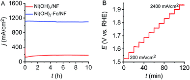 | ||
| Fig. 4 (A) CPEs at 1.70 V vs. RHE of the Ni(OH)2/NF and Ni(OH)2–Fe/NF electrodes. (B) Multi-current process at the Ni(OH)2–Fe/NF electrode. | ||
A multi-step chronopotentiometry experiment was conducted to further examine the electrocatalyst stability for OER at different catalytic current densities in 10 M KOH solution. The applied current density was increased stepwise from 200 to 2400 mA cm−2 with an increment of 200 mA cm−2 per 10 min. As shown in Fig. 4B, the recorded potentials at each current density remain constant and no sign of deactivation is observed within the test period, indicating the high stability of the Ni(OH)2–Fe/NF electrode within a wide range of current density. These chronopotentiometric responses indicates efficient charge transfer and excellent mass transport properties of the 3D hierarchical Ni(OH)2–Fe/NF electrode.
Conclusions
In summary, we report the in situ autologous growth of ultrathin Ni(OH)2 nanosheet with incorporation of Fe at ambient temperature without any energy input and its application as a high-performance OER electrocatalyst. The electrocatalytic performance of the hierarchical electrodes can be easily adjusted by varying the immersion time of Ni(OH)2 nanosheet in Fe(III) solution. Benefiting from its unique and integrated nanostructures, this hierarchically structured electrode displays excellent electrocatalytic activity and stability toward water oxidation. In 1 M KOH, the Ni(OH)2–Fe/NF electrode can deliver a current density of 1000 mA cm−2 at an overpotential of only 330 mV. The facile preparation approach with no energy input and the high performance of this Earth-abundant material electrode toward water oxidation are appealing for practical applications in large-scale water splitting.Conflicts of interest
There are no conflicts to declare.Acknowledgements
This work was supported by the National Natural Science Foundation of China (21573160, 21872105), the Natural Science Foundation of Jiangsu Province (BK20181211), and Science & Technology Commission of Shanghai Municipality (14DZ2261100).Notes and references
- I. Roger, M. A. Shipman and M. D. Symes, Nat. Rev. Chem., 2017, 1, 1 CrossRef.
- M. S. Dresselhaus and I. L. Thomas, Nature, 2001, 414, 332–337 CrossRef CAS.
- X. Zou and Y. Zhang, Chem. Soc. Rev., 2015, 44, 5148–5180 RSC.
- Y. X. Chen, K. N. Yang, B. Jiang, J. X. Li, M. Q. Zeng and L. Fu, J. Mater. Chem. A, 2017, 5, 8187–8208 RSC.
- N. T. Suen, S. F. Hung, Q. Quan, N. Zhang, Y. J. Xu and H. M. Chen, Chem. Soc. Rev., 2017, 46, 337–365 RSC.
- M. G. Walter, E. L. Warren, J. R. McKone, S. W. Boettcher, Q. Mi, E. A. Santori and N. S. Lewis, Chem. Rev., 2010, 110, 6446–6473 CrossRef CAS.
- J. Du, Z. Chen, S. Ye, B. J. Wiley and T. J. Meyer, Angew. Chem., Int. Ed. Engl., 2015, 54, 2073–2078 CrossRef CAS.
- L. Han, S. Dong and E. Wang, Adv. Mater., 2016, 28, 9266–9291 CrossRef CAS.
- M. M. Najafpour, G. Renger, M. Holynska, A. N. Moghaddam, E. M. Aro, R. Carpentier, H. Nishihara, J. J. Eaton-Rye, J. R. Shen and S. I. Allakhverdiev, Chem. Rev., 2016, 116, 2886–2936 CrossRef CAS.
- I. Roger and M. D. Symes, J. Mater. Chem. A, 2016, 4, 6724–6741 RSC.
- C. Dong, T. Kou, H. Gao, Z. Peng and Z. Zhang, Adv. Energy Mater., 2018, 8, 1701347 CrossRef.
- D. Zhou, S. Wang, Y. Jia, X. Xiong, H. Yang, S. Liu, J. Tang, J. Zhang, D. Liu, L. Zheng, Y. Kuang, X. Sun and B. Liu, Angew. Chem., Int. Ed. Engl., 2019, 58, 736–740 CrossRef CAS.
- J. Y. Wang, L. L. Ji and Z. F. Chen, ACS Catal., 2016, 6, 6987–6992 CrossRef CAS.
- M. W. Louie and A. T. Bell, J. Am. Chem. Soc., 2013, 135, 12329–12337 CrossRef CAS.
- B. J. Trzesniewski, O. Diaz-Morales, D. A. Vermaas, A. Longo, W. Bras, M. T. Koper and W. A. Smith, J. Am. Chem. Soc., 2015, 137, 15112–15121 CrossRef CAS.
- B. S. Yeo and A. T. Bell, J. Phys. Chem. C, 2012, 116, 8394–8400 CrossRef CAS.
- X. Lu and C. Zhao, Nat. Commun., 2015, 6, 6616 CrossRef CAS.
- J. Y. C. Chen, J. T. Miller, J. B. Gerken and S. S. Stahl, Energy Environ. Sci., 2014, 7, 1382–1386 RSC.
- J. Ji, L. L. Zhang, H. Ji, Y. Li, X. Zhao, X. Bai, X. Fan, F. Zhang and R. S. Ruoff, ACS Nano, 2013, 7, 6237–6243 CrossRef CAS.
- G. Abellan, J. A. Carrasco, E. Coronado, J. P. Prieto-Ruiz and H. Prima-Garcia, Adv. Mater. Interfaces, 2014, 1, 1400184 CrossRef.
- G. Chen, T. Wang, J. Zhang, P. Liu, H. Sun, X. Zhuang, M. Chen and X. Feng, Adv. Mater., 2018, 30, 1706279 CrossRef.
- W. Zhang, J. Qi, K. Q. Liu and R. Cao, Adv. Energy Mater., 2016, 6, 1502489 CrossRef.
- Y. Liu, X. Liang, L. Gu, Y. Zhang, G. D. Li, X. Zou and J. S. Chen, Nat. Commun., 2018, 9, 2609 CrossRef.
- J. Y. Wang, L. L. Ji, S. S. Zuo and Z. F. Chen, Adv. Energy Mater., 2017, 7, 1700107 CrossRef.
- X. Yang, C.-J. Wang, C.-C. Hou, W.-F. Fu and Y. Chen, ACS Sustainable Chem. Eng., 2018, 6, 2893–2897 CrossRef CAS.
- H. Wu, X. Lu, G. F. Zheng and G. W. Ho, Adv. Energy Mater., 2018, 8, 1702704 CrossRef.
- W. X. Zhu, T. S. Zhang, Y. Zhang, Z. H. Yue, Y. G. Li, R. Wang, Y. W. Ji, X. P. Sun and J. L. Wang, Appl. Catal., B, 2019, 244, 844–852 CrossRef CAS.
- L. Hui, Y. Xue, B. Huang, H. Yu, C. Zhang, D. Zhang, D. Jia, Y. Zhao, Y. Li, H. Liu and Y. Li, Nat. Commun., 2018, 9, 5309 CrossRef.
- J. F. Marco, J. R. Gancedo, M. Gracia, J. L. Gautier, E. Rios and F. J. Berry, J. Solid State Chem., 2000, 153, 74–81 CrossRef CAS.
- C. Yuan, J. Li, L. Hou, X. Zhang, L. Shen and X. W. D. Lou, Adv. Funct. Mater., 2012, 22, 4592–4597 CrossRef CAS.
- C. Xiao, Y. Li, X. Lu and C. Zhao, Adv. Funct. Mater., 2016, 26, 3515–3523 CrossRef CAS.
- Y. Liang, Q. Liu, A. M. Asiri, X. Sun and Y. He, Int. J. Hydrogen Energy, 2015, 40, 13258–13263 CrossRef CAS.
Footnote |
| † Electronic supplementary information (ESI) available. See DOI: 10.1039/c9ra04368c |
| This journal is © The Royal Society of Chemistry 2019 |

