
 Open Access Article
 This Open Access Article is licensed under a Creative Commons Attribution-Non Commercial 3.0 Unported Licence
Synthesis, growth mechanism and photocatalytic H2 evolution of CdS/CuS composite via hydrothermal method
Xiande Yang†
ab,
Guangwen Lu†a,
Boyou Wanga,
Tinglan Wanga and
Yongqian Wang *ac
*ac
aEngineering Research Center of Nano-Geomaterials of Ministry of Education, Faculty of Material Science and Chemistry, China University of Geosciences, 388 Lumo Road, Wuhan 430074, P. R. China. E-mail: cugwyq@126.com; Tel: +86 138-7137-9285
bCollege of Chemistry and Material Science, Nanning Normal University, Nanning 530001, P. R. China
cGuangdong Provincial Key Laboratory of Soil and Groundwater Pollution Control, Shenzhen 518055, P. R. China
First published on 13th August 2019
Abstract
In recent years, visible light-driven photocatalysts used for confronting energy shortages and environmental pollution have drawn much attention. CdS is regarded as an excellent photoelectric semiconductor for photocatalysis, but photocorrosion and low photocatalytic activity limit its practical application. In order to improve the photocatalytic performance of CdS, we synthesized a II-type CdS/CuS composite via a hydrothermal method in one step. CdS, CuS and the CdS/CuS composite have flower-like structures according to FESEM results. XRD and EDS results confirm that the composite is composed of CdS and CuS, indicating that we have successfully synthesized the CdS/CuS composite. UV-Vis and PL results show that the formation of heterojunction structures with CuS can be used to control the optical properties of CdS. H2 evolution results show that the CdS/CuS composite generates H2 at a rate of 295 μmol g−1 h−1, which is higher than that of CdS.
1. Introduction
Energy consumption and environmental pollution have become a crisis due to the development of modern living standards; it is a challenge for us to find an efficient way to solve these problems.1 In past research reports, hydrogen energy has been considered a sustainable and clean form of energy, and it can be abundantly obtained by splitting of water into hydrogen using nanomaterials, which is a promising and attractive strategy for confronting the above issues.2–4 Thus, various nanomaterials have been used as effective photocatalysts for splitting water to produce H2, such as TiO2,5 ZnO,6 g-C3N4,7 CuS8 and BiVO4.9 In addition, photocatalytic H2 evolution is critically related to the size, structure, surface area and morphology of the nanomaterials used.10 Therefore, various morphologies of nanomaterials have been reported, such as ZnO nanorods,11 TiO2 nanospheres,12 MoS2 nanosheets,13 and flower-like CdS structures.14 However, in the field of photocatalytic nanomaterials, the major challenge is to find efficient and stable nanomaterials for photocatalytic application under solar light.Among these types of nanomaterials, CdS has attracted much attention due to its conduction band position and band gaps being suitable for energy conversion under visible light.15 As is known, CdS (2.42 eV) is an important visible light photocatalyst because of its sensitivity to visible light irradiation and efficient photoexciton generation, which are excellent qualities for a photocatalyst.16,17 However, CdS has some disadvantages for further application. First, CdS nanostructures can easily aggregate during photocatalytic reactions, which can reduce the surface area. Second, the photoexciton recombination is ultrafast, and there is a lack of reactive sites.18 Third, instability occurs due to photocorrosion or photodissolution.19 Therefore, CdS usually exhibits low photocatalytic activity due to the above drawbacks. To solve these problems, significant efforts have been devoted to improving the photocatalytic activity of CdS. Examples include the synthesis of CdS quantum dots with high surface areas,20 deposition of noble metals,21 loading cocatalysts onto the CdS surface,22 metal ion doping,23 and the incorporation with other semiconductors to form heterojunction structures.24
In comparison with noble metal cocatalyst addition and metal ion doping, the hybridization of CdS with other semiconductors having matching band gaps to form heterojunction structures is beneficial for suppressing the recombination of photoinduced charge carriers. Furthermore, this approach can effectively improve spatial charge separation and prolong the lifetime of the charge carriers, which can enhance the photocatalytic properties.25 In addition, this charge separation is better facilitated by a II-type system than a I-type system.26 Therefore, we tried to synthesize a II-type CdS heterojunction structure in one step to enhance the photocatalytic activity. CuS is an important semiconductor due to its excellent physical and chemical properties with a band gap of about 2.0 eV, with potential applications in photocatalysis, photothermal conversion, and solar cells.27 Markovskaya et al. prepared the noble-metal-free photocatalyst CuS/Cd0.3Zn0.7S and found that the photocatalytic activity reached as high as 3520 μmol g−1 h−1.28 Markovskaya et al. also synthesized Cd0.3Zn0.7S nanoparticles with CuxS and Cu0 as co-catalysts, which achieved a photocatalytic hydrogen evolution of 6.4 mmol g−1 h−1.29 Chen et al. presented well-defined Cu1.94S–ZnxCd1−xS heteronanorods for photocatalytic hydrogen evolution, which showed a hydrogen production activity of 7735 μmol g−1 h−1.30 Benefiting from the excellent optical performance and matched band gap of CuS, we fabricated a II-type CdS/CuS composite through a hydrothermal method in one step. We have described the growth mechanism, optical properties and H2 evolution reaction of CdS/CuS composites with different molar ratios of Cd![[thin space (1/6-em)]](https://www.rsc.org/images/entities/char_2009.gif) :Cu. Compared with pure CdS, the CdS/CuS composite exhibited better photocatalytic efficiency for H2 evolution and generated H2 at a rate of 295 μmol g−1 h−1 when the molar ratio of Cd:Cu was 0.5:0.5. Thus, CuS plays an important role in improving the photocatalytic activity.
:Cu. Compared with pure CdS, the CdS/CuS composite exhibited better photocatalytic efficiency for H2 evolution and generated H2 at a rate of 295 μmol g−1 h−1 when the molar ratio of Cd:Cu was 0.5:0.5. Thus, CuS plays an important role in improving the photocatalytic activity.
2. Experimental
2.1 Synthesis of CdS, CuS, and CdS/CuS composite
All the chemicals used in this work were of analytical reagent grade. Cadmium nitrate (Cd(NO3)2·4H2O), cupric nitrate (Cu(NO3)2·3H2O), and thiourea were used without any further purification. The aqueous solutions were made using deionized water.Scheme 1: first, 0.008 mol Cd(NO3)2·4H2O and 0.002 mol Cu(NO3)2·3H2O were added into a beaker containing 90 mL deionized water with stirring for 10 minutes. Then, we added 0.032 mol thiourea into the aqueous solution (Cd:S = 1:3, Cu:S = 1:4, molar ratio). After stirring for 10 minutes, the aforementioned solution was transferred to a Teflon-lined autoclave of 120 mL capacity.
Scheme 2: first, 0.002 mol Cu(NO3)2·3H2O and 0.02 mol thiourea were added into a beaker containing 90 mL deionized water with stirring for 10 minutes. Then, we added 0.008 mol Cd(NO3)2·4H2O into the aqueous solution. After stirring for 10 minutes, the aforementioned solution was transferred to a Teflon-lined autoclave of 120 mL capacity. The amount of thiourea was fixed at 0.02 mol.
Scheme 3: first, 0.008 mol Cd(NO3)2·4H2O and 0.02 mol thiourea were added into a beaker containing 90 mL deionized water with stirring for 10 minutes. Then, we added 0.002 mol Cu(NO3)2·3H2O into the aqueous solution. After stirring for 10 minutes, the aforementioned solution was transferred into a Teflon-lined autoclave of 120 mL capacity. The amount of thiourea was again fixed at 0.02 mol.
All the autoclaves were sealed and maintained at 160 °C for 24 h. Afterwards, the autoclaves were cooled to room temperature naturally. The resulting products were repeatedly washed with deionized water and absolute ethanol several times. Finally, the final products were dried at 60 °C in air. We varied the concentration of cupric nitrate (Cd2+:Cu2+ = 0.6:0.4, 0.5:0.5, 0.4:0.6, 0.2:0.8, molar ratio) to synthesize the CdS/CuS composites. For the purpose of comparison, the pure CdS and CuS were prepared under the same conditions.
2.2 Characterization
The crystal phases of CdS, CuS, and CdS/CuS were measured by powder X-ray diffraction (PXRD, D8-Focus, Bruker AXS) with Ni-filtered and Cu Kα radiation (λ = 1.5406 Å). The morphologies of the as-prepared samples were characterized by field emission scanning electron microscopy (FESEM, SU8010, HITACHI). A scanning electron microscope (SEM, Coxem EM-30AX PLUS+) equipped with an energy dispersive spectrometer (EDS, Bruker Nano Xflash610-H) was used to analyze the chemical composition at the sample surface. The optical absorption and room temperature photoluminescence spectra (PL) of the samples were obtained on an ultraviolet-visible spectrophotometer (UV-Vis, UV-2600, Shimadzu) and a fluorescence spectrophotometer (F-4500, HITACHI) equipped with a Xe lamp (excitation wavelength is 338 nm).2.3 Photocatalytic H2 evolution
Photocatalytic H2 evolution was performed in a quartz reactor under visible light irradiation. 0.1 g sample was dispersed in 90 mL DI water in a quartz reactor, and then 10 mL triethanolamine and 1 mL H2PtCl6 aqueous solution were added into the aqueous solution under stirring. In this process, triethanolamine was added as a sacrificial electron donor, and H2PtCl6 was added to reduce Pt as a cocatalyst. After that, the quartz reactor was purged with N2 for 15 min to remove air and sealed with a rubber stopper. The Pt cocatalyst was reduced by H2PtCl6 under irradiation for 1 h with visible light. Finally, the photocatalytic water splitting reaction was irradiated under the same visible light. The H2 content was analyzed by a gas chromatograph at a rate of 1 mL gas each hour.3. Results and discussion
3.1 FESEM results of CdS, CuS and CdS/CuS composite
Fig. 1 shows the FESEM images of CdS and CuS. We can see from Fig. 1 that the morphology of CdS is a flower-like structure, assembled by nanoparticles. The diameter of the flower-like CdS is about 5 μm. The morphology of CuS is also a flower-like structure assembled by nanosheets, with a diameter of about 2 μm. This means that both CdS and CuS are flower-like structures.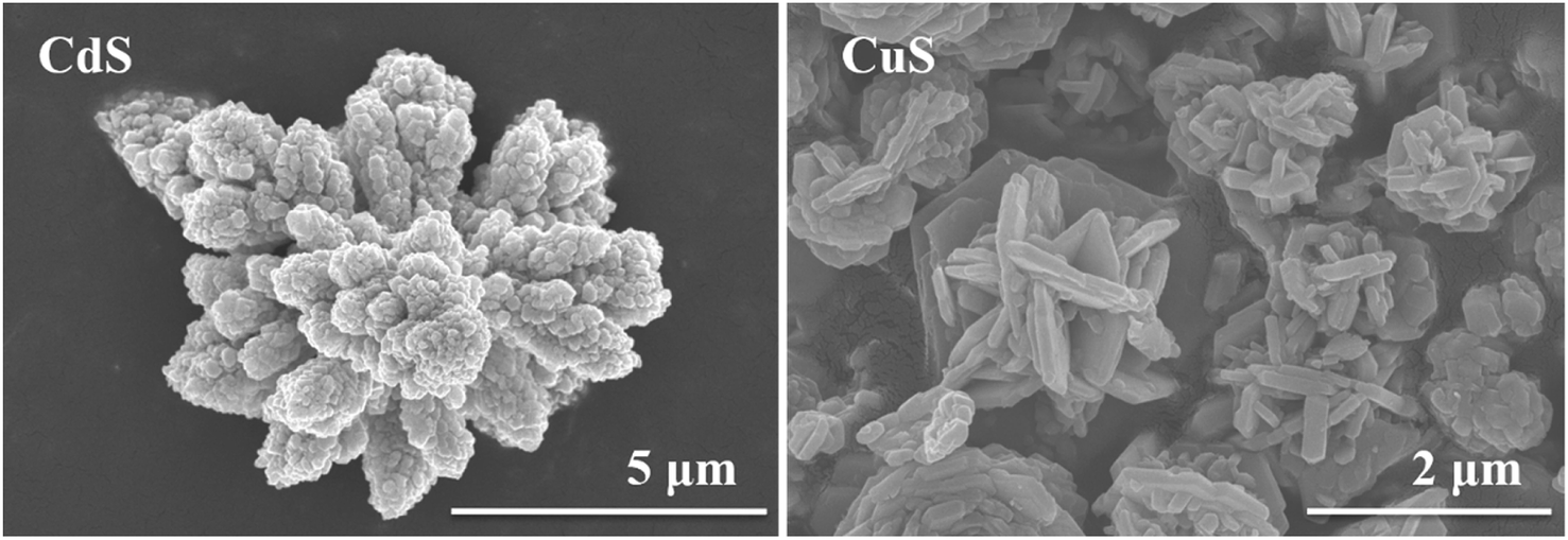 | ||
| Fig. 1 FESEM images of CdS and CuS. | ||
Fig. 2 shows the FESEM images of the CdS/CuS composite, synthesized through Scheme 1, at different molar ratios of Cd:Cu. As shown in Fig. 2, the CdS/CuS composites are flower-like structures with different molar ratios of Cd:Cu. The nanoparticles are composed of CdS, and the nanosheets are composed of CuS. When the Cu source is increased, the flower-like structure becomes increasingly assembled by nanosheets.
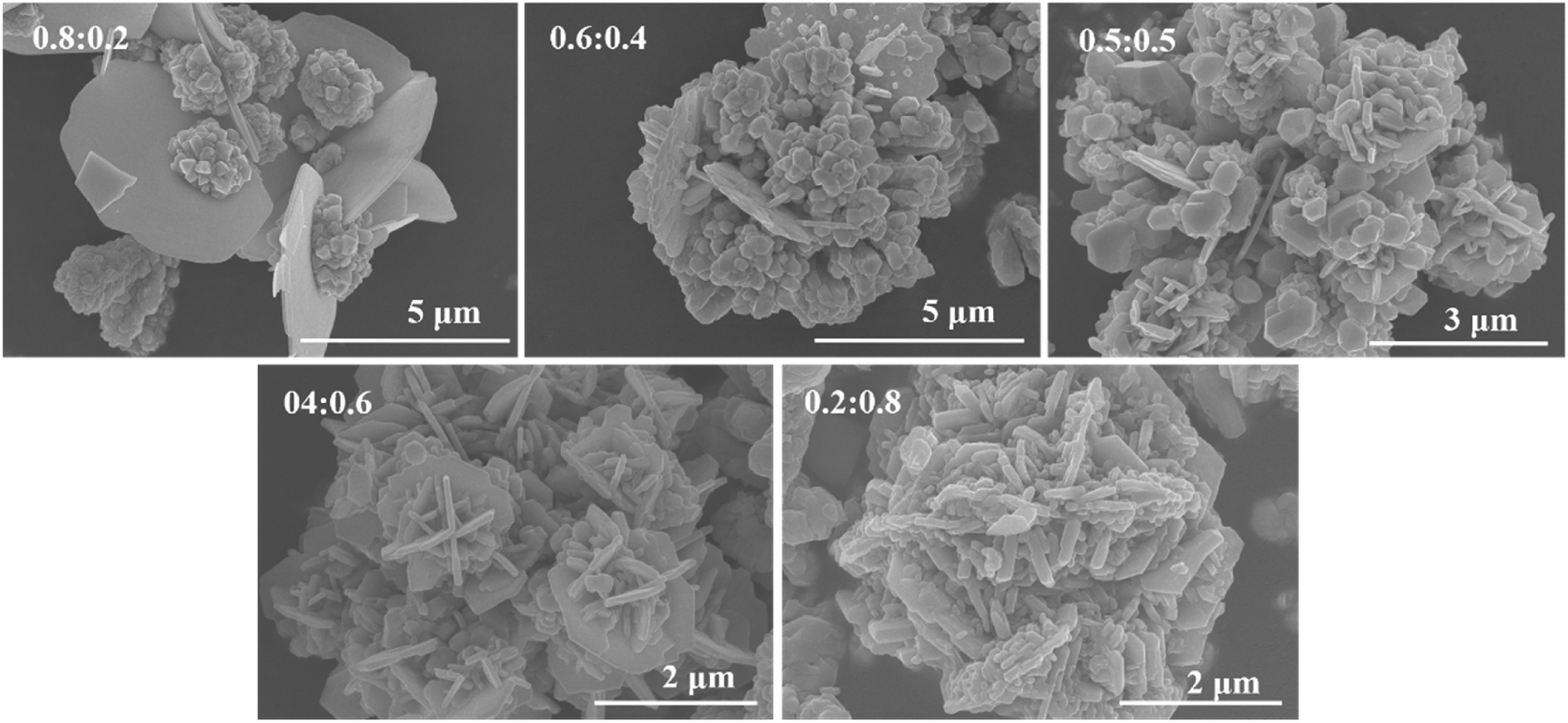 | ||
| Fig. 2 FESEM images of CdS/CuS composite at different ratios of Cd:Cu through Scheme 1. | ||
Fig. 3 shows the FESEM images of the CdS/CuS composite, synthesized through Scheme 2. Fig. 3 shows that the flower-like CdS/CuS composites are mainly assembled by nanosheets with different molar ratios of Cd:Cu using Scheme 2. The amount of the Cu source did not obviously affect the morphologies of the CdS/CuS composites as the molar ratios of Cd:Cu increased.
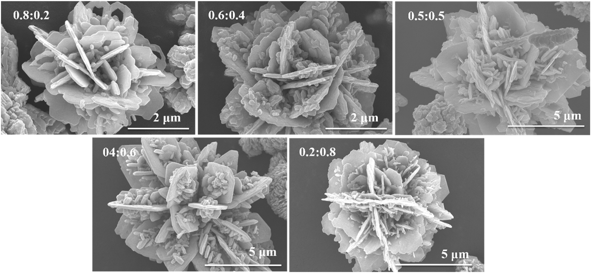 | ||
| Fig. 3 FESEM images of CdS/CuS composite at different ratios of Cd:Cu through Scheme 2. | ||
Fig. 4 shows the FESEM images of the CdS/CuS composite, synthesized through Scheme 3. We can see from Fig. 4 that the morphologies of the CdS/CuS composites are mainly assembled by nanoparticles at high molar ratios of the Cd source. However, when the amount of the Cu source is increased, the flower-like structure becomes increasingly assembled by nanosheets.
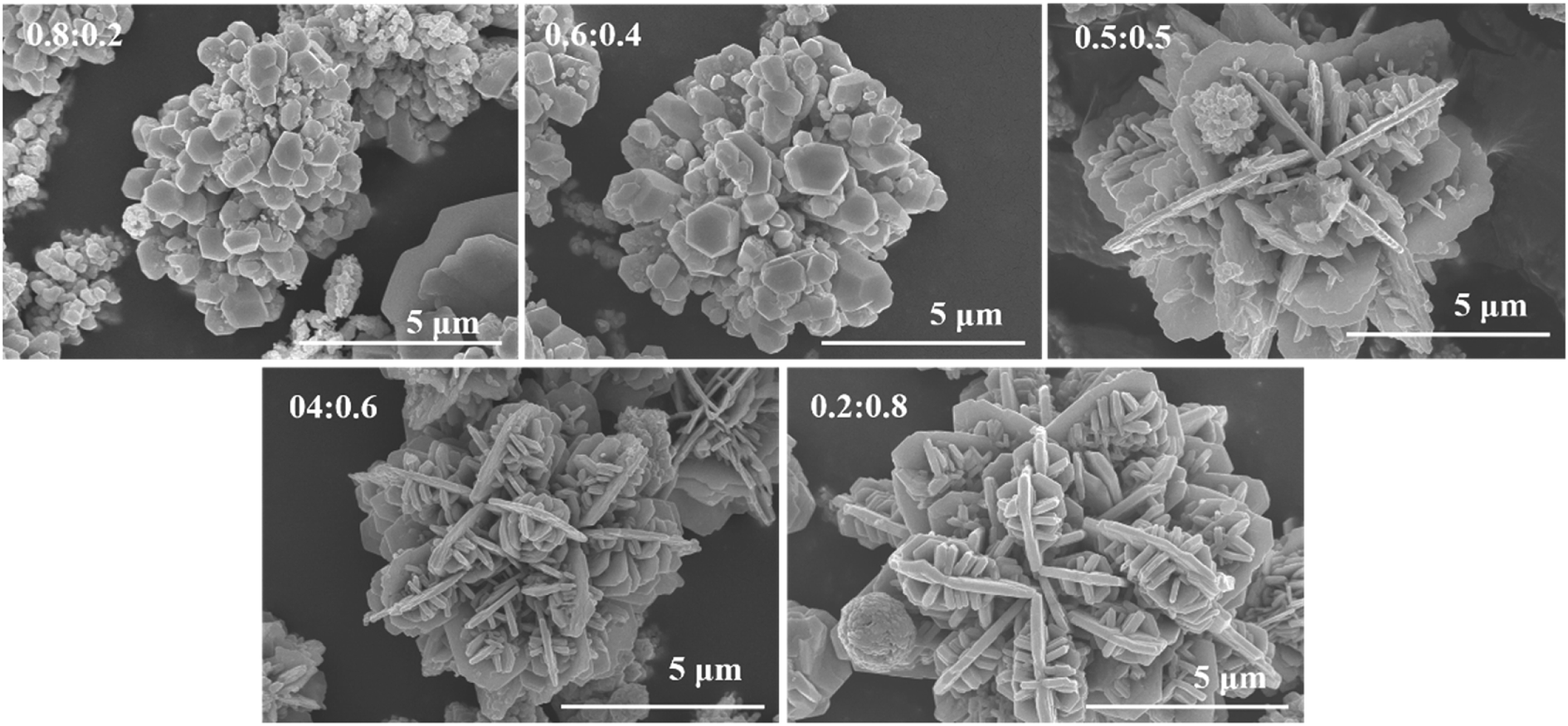 | ||
| Fig. 4 FESEM images of CdS/CuS composite at different ratios of Cd:Cu through Scheme 3. | ||
In Scheme 1, a Cd source and Cu source were combined in a beaker, with an amount of thiourea that was sufficient for Cd2+ and Cu2+ to form a strong ligand compound. The CdS/CuS composites were mainly assembled by nanoparticles and nanosheets with low amounts of the Cu source, and the composites were mainly assembled by nanosheets with high amounts of the Cu source. In Scheme 2, the Cu source and thiourea were first added to the beaker; thus, Cu2+ may firstly form a strong ligand compound with thiourea. As the stability of Cu ligand compound is stronger than that of the Cd ligand compound, the CdS/CuS composites were mainly assembled by nanosheets with limited amounts of thiourea at different molar ratios of Cd:Cu. In Scheme 3, the Cd source and thiourea were first added into the beaker; thus, Cd2+ may firstly form a ligand compound with thiourea. The CdS/CuS composites were mainly assembled by nanoparticles with high molar ratios of the Cd source. According to the FESEM results shown in Fig. 2 to Fig. 4, we chose the as-prepared samples from Scheme 3 for characterization by XRD, EDS, UV-Vis, PL and H2 evolution analyses.
3.2 XRD results of CdS, CuS and CdS/CuS composite
Fig. 5 displays the XRD patterns of CdS, CuS and the CdS/CuS composite at different molar ratios of Cd:Cu before and after photocatalytic H2 evolution. Fig. 5A shows that the diffraction peaks of CdS and CuS were well-indexed to the hexagonal phase of CdS (JSPDS card no. 41-1049) and the hexagonal phase of CuS (JSPDS card no. 06-0464). No peaks belonging to any other phases or impurities were detected. When the molar ratio of Cd:Cu was 0.8:0.2, the mixed peaks were attributed to CdS and CuS. The diffraction peaks belonged to CuS when 2θ was 29.2°, 31.7°, and 32.8°. When the molar ratio of Cd:Cu was 0.6:0.4, we can find the peak attributed to CuS at 2θ = 59.2°. When the molar ratio of Cd:Cu was 0.5:0.5, we can find the peak belonging to CuS at 2θ = 10.7°. Furthermore, the intensity of the diffraction peaks belonging to CuS increased when the molar ratios of Cd:Cu changed from 08:0.2 to 0.2:0.8. The diffraction peak at 2θ = 47.9° belongs to CdS and CuS, and the intensity of this diffraction peak also increased with the change in the molar ratios of Cd:Cu. On the other hand, the intensity of some diffraction peaks belonging to CdS decreased at different molar ratios of Cd:Cu. Therefore, we confirmed that we successfully synthesized the CdS/CuS composite based on the XRD results. In addition, the samples exhibit stable photocatalytic activity for H2 evolution. Fig. 5B shows a small difference in the XRD patterns after the H2 evolution test, which implies that the CdS, CuS and CdS/CuS samples exhibit excellent stability for H2 evolution under visible light irradiation.
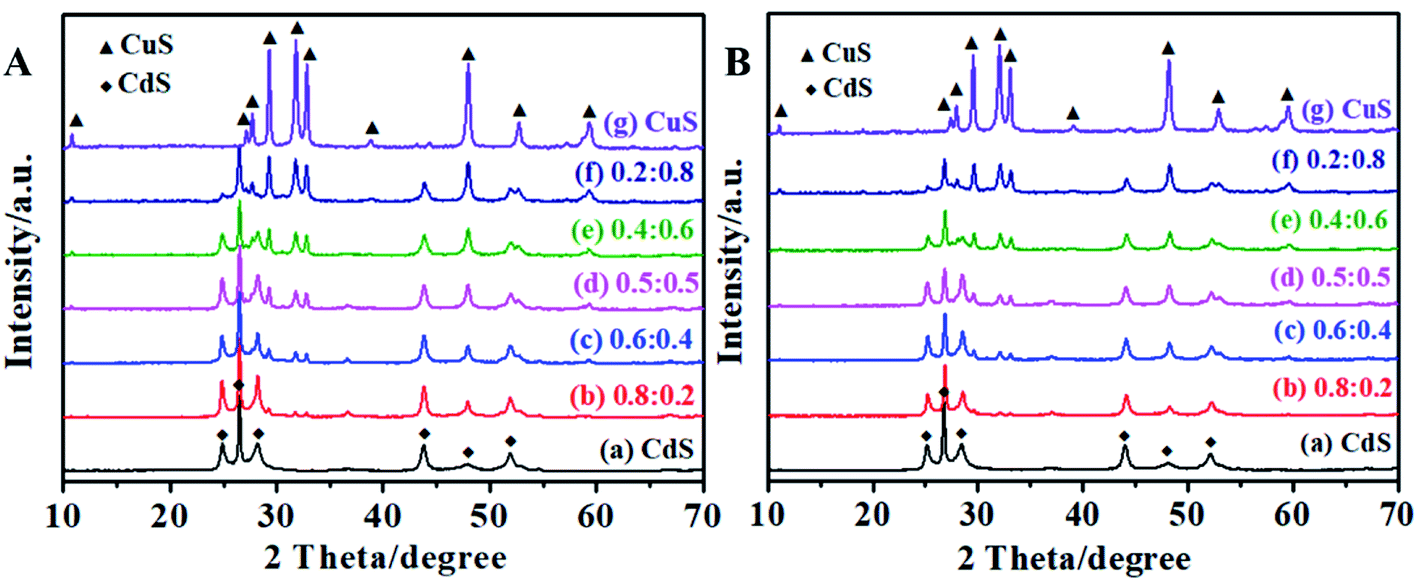 | ||
| Fig. 5 XRD patterns of CdS, CuS and CdS/CuS composite at different ratios of Cd:Cu. (A) Before photocatalysis. (B) After photocatalysis. | ||
3.3 EDS results of CdS, CuS and CdS/CuS composite
Fig. 6 presents the EDS results for CdS, CuS and the CdS/CuS composite when the molar ratio of Cd:Cu is 0.5:0.5, synthesized following Scheme 3. We can see from Fig. 6A that the elemental composition calculated using EDS analysis was 23 and 77 wt% of S and Cd, respectively, and the atomic ratio of S:Cd was about 1:1. Shown in Fig. 6B, the elemental composition calculated by EDS was 36 and 64 wt% of S and Cu, respectively, with an atomic ratio of S:Cu that was about 1:1. These results show that the samples contained pure CdS and CuS. As shown in Fig. 6C, the elemental composition was 28, 28, 44 wt% of S, Cu, Cd, respectively, calculated using EDS analysis, with the atomic ratio of S:Cd, S:Cu of about 1:1. Therefore, the composites are composed of CdS and CuS. Fig. 7 shows the EDS mapping results of the CdS/CuS composite when the molar ratio of Cd:Cu was 0.5:0.5, synthesized following Scheme 3. We can see from Fig. 7 that the elemental composition of the CdS/CuS composite includes Cd, Cu, and S elements. The nanoparticles belong to the Cd element and the nanosheets belong to the Cu element. Therefore, we confirm that we have successfully synthesized the CdS/CuS composite from EDS results.
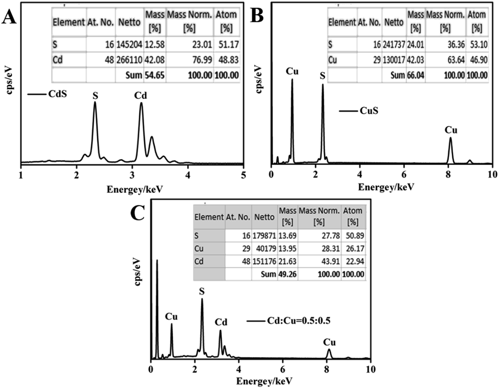 | ||
| Fig. 6 EDS analysis of CdS, CuS and CdS/CuS composite. | ||
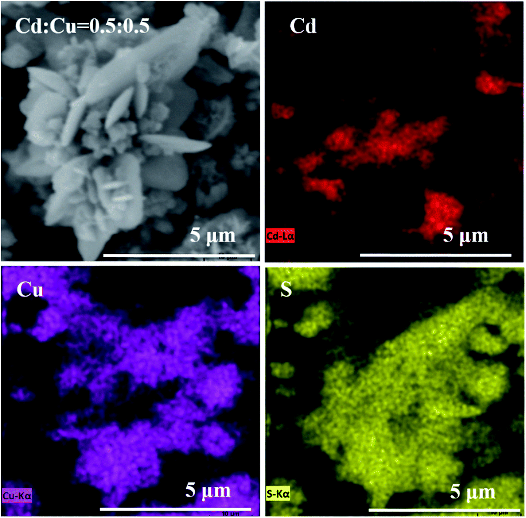 | ||
| Fig. 7 EDS mapping of CdS/CuS composite when the molar ratio of Cd:Cu is 0.5:0.5. | ||
3.4 UV-Vis and PL tests of CdS, CuS and CdS/CuS composite
Fig. 8 presents the UV-Vis absorption spectra and PL spectra for CdS, CuS and the CdS/CuS composite at different ratios of Cd:Cu. It can be seen from Fig. 8A that the flower-like CdS structure strongly absorbs in the visible light region upto 520 nm. The flower-like CuS structure showed a strong absorption peak at 620 nm. When CdS and CuS form the CdS/CuS composite, the absorption edge shifts toward longer wavelengths because of the contribution from CuS, which has an absorption peak at 620 nm. Thus, the absorption edge of the CdS/CuS composite shifts toward a wavelength of about 600 nm when the amount of Cu source is increased. Therefore, forming the heterojunction structure with CuS can be used to improve the absorption capability of CdS for visible light. Fig. 8B shows the PL spectra of CdS, CuS and the CdS/CuS composite at different molar ratios. We can see from Fig. 8B that all the samples have a similar emission peak at 370 nm, and the flower-like CdS has another wide emission peak at 582 nm. With the increase in the amount of Cu source, the peak near 582 nm disappears. The possible cause is that the composites have a CuS composition. As we know, PL spectra reveal the efficiency of charge carrier trapping, immigration and transfer.31 Thus, the decreased intensity of the PL spectra indicate the lower recombination rate of the photogenerated electrons and holes, leading to higher photocatalytic activity. Therefore, we can confirm based on Fig. 8 that the formation of a heterojunction structure with CuS can be used to control the optical properties of CdS.
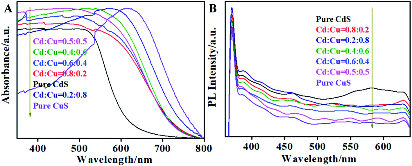 | ||
| Fig. 8 (A) UV-Vis absorption spectra, (B) PL spectra of CdS, CuS and CdS/CuS composite at different ratios of Cd:Cu. | ||
3.5 Growth mechanism of CdS, CuS and CdS/CuS composite
Fig. 9 shows the growth mechanism of CdS, CuS and the CdS/CuS composite. For CdS, Cd2+ and thiourea formed a strong Cd–thiourea ligand compound; Cd2+ and S2− were then slowly released and formed CdS nanoparticles. Additionally, the anisotropy of CdS would increase. Several CdS nanoparticles assembled together to form flower-like structures.32 For CuS, Cu2+ and thiourea formed a Cu–thiourea ligand compound, and then, the ligand compound released Cu2+ and S2− slowly and formed CuS nanosheets upon heating. Then, several CuS nanosheets assembled together to form flower-like structures. For the CdS/CuS composite, Cd2+ and Cu2+ each formed a strong ligand compound with thiourea. After heating at a high temperature, the ligand compounds slowly released Cu2+, Cd2+ and S2−, which formed CdS nanoparticles and CuS nanosheets.33 On account of the limited thiourea, Cu2+ and Cd2+ share the thiourea, which releases S2−. Then, CdS nanoparticles and CuS nanosheets assemble to form a flower-like composite. Therefore, we can fabricate flower-like CdS/CuS composites in one step through a hydrothermal method.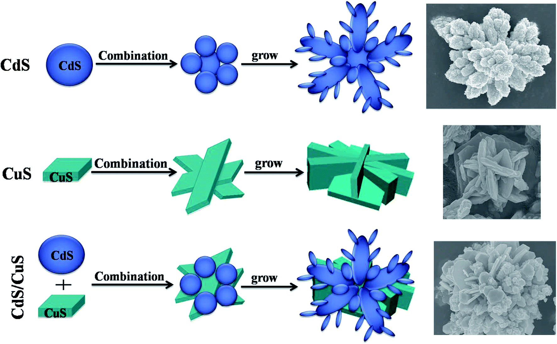 | ||
| Fig. 9 Growth mechanism of CdS, CuS and CdS/CuS composite. | ||
3.6 Photocatalytic H2 evolution of CdS, CuS and CdS/CuS composite
The visible light photocatalytic H2 evolution reaction (HER) of CdS, CuS and the CdS/CuS composite is shown in Fig. 10A. The results show that all the samples perform H2 evolution because CdS and CuS have absorption in the visible light region. We can see from Fig. 10A that pure CdS and pure CuS each generate H2 at rates of 207 μmol g−1 h−1 and 219 μmol g−1 h−1, respectively. After we synthesized the CdS/CuS composites with different ratios of Cd:Cu, the increased efficiency of the H2 production compared to that of pure CdS or pure CuS becomes evident. When the ratio of Cd:Cu is 0.5:0.5, the CdS/CuS composites generate H2 at a rate of 295 μmol g−1 h−1, which benefits from the constructed CdS/CuS heterojunction. The increase in the size of the CdS/CuS composite did not obviously increase the efficiency of H2 production. These results show that the micro-sized CdS/CuS composite could be synthesized as nanosized to further enhance H2 production because of nanosized materials have larger specific surface. As is shown in Fig. 10B, when CuS combines with CdS to construct a II-type heterojunction, the visible light-excited electrons in the conduction band (CB) of CuS can transfer into the CB of CdS, and the holes in the valence band (VB) of CdS can transfer into the VB of CuS, which can enhance the separation of the photoinduced charge carriers and holes.34,35 In this way, the efficient separation of photogenerated electron–hole pairs can be achieved, which further improves the visible light photocatalytic H2 evolution activity. Therefore, forming heterojunction structure with CuS can be used to enhance H2 production of CdS.
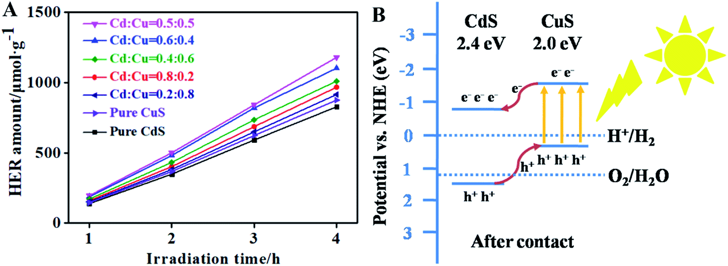 | ||
| Fig. 10 (A) Time courses of H2 evolution with CdS, CuS and CdS/CuS composite, (B) schematic diagram of electronic transfer mechanism. | ||
4. Conclusions
In summary, we have synthesized a CdS/CuS composite through a hydrothermal method in one step. FESEM images show a flower-like morphology for CdS, CuS and the CdS/CuS composite synthesized following different schemes. EDS results also confirm that all the composites are composed of CdS and CuS. XRD results show that pure CdS and pure CuS are in the hexagonal phase, and the CdS/CuS composites have diffraction peaks belonging to CdS and CuS with different ratios of Cd:Cu. UV-Vis and PL spectroscopy results show that forming a heterojunction structure with CuS can be used to control the optical properties of CdS. H2 evolution results show that the CdS/CuS composite generates H2 at a rate of 295 μmol g−1 h−1, which is higher than that of pure CdS. Therefore, forming a heterojunction structure with CuS can be used to enhance the H2 production of CdS.
Funding information
This work was supported by the National Natural Science Foundation of China (No. 41472042 and 41172051), Guangdong Provincial Key Laboratory of Soil and Groundwater Pollution Control (No. 2017B030301012), Open Research Topic for Engineering Research Center of Nano-Geomaterials of Ministry of Education of China University of Geosciences (No. NGM2018KF019), the financial support was gratefully appreciated.Conflicts of interest
There are no conflicts to declare.References
- H. Yang, Z. L. Jin, D. D. Liu, K. Fan and G. R. Wang, Visible Light Harvesting and Spatial Charge Separation over the Creative Ni/CdS/Co3O4 Photocatalyst, J. Phys. Chem. C, 2018, 122, 10430–10441 CrossRef CAS.
- A. Fujishima and K. Honda, Electrochemical Photocatalysis of Water at a Semiconductor Electrode, Nature, 1972, 238, 37–38 CrossRef CAS PubMed.
- Q. Li, B. D. Guo, J. G. Yu, J. R. Ran, B. H. Zhang, H. J. Yan and J. R. Gong, Highly Efficient Visible-Light-Driven Photocatalytic Hydrogen Production of CdS-Cluster-Decorated Graphene Nanosheets, J. Am. Chem. Soc., 2011, 133, 10878–10884 CrossRef CAS PubMed.
- H. Tong, S. X. Ouyang, Y. P. Bi, N. T. Umezawa, M. Oshikiri and J. H. Ye, Nano-Photocatalytic Materials: Possibilities and Challenges, Adv. Mater., 2012, 24, 229–251 CrossRef CAS PubMed.
- Y. C. Li, Q. Ma, J. Han, L. L. Ji, J. X. Wang, J. Y. Chen and Y. Q. Wang, Controllable Preparation, Growth Mechanism and the Properties Research of TiO2 Nanotube Arrays, Appl. Surf. Sci., 2014, 297, 103–108 CrossRef CAS.
- Y. Q. Wang, Q. Ma, H. X. Jia and Z. S. Wang, One-Step Solution Synthesis and Formation Mechanism of Flower-like ZnO and its Structural and Optical Characterization, Ceram. Int., 2016, 42, 10751–10757 CrossRef CAS.
- G. G. Zhang, Z. A. Lan, L. H. Lin, S. Lin and X. C. Wang, Overall Water Splitting by Pt/g-C3N4 Photocatalysts without Using Sacrificial Agents, Chem. Sci., 2016, 7, 3062–3066 RSC.
- Q. W. Tian, M. H. Tang, Y. G. Sun, R. J. Zou, Z. G. Chen, M. F. Zhu, S. P. Yang, J. L. Wang, J. H. Wang and J. Q. Hu, Hydrophilic Flower-Like CuS Superstructures as an Efficient 980 nm Laser-Driven Photothermal Agent for Ablation of Cancer Cells, Adv. Mater., 2011, 23, 3542–3547 CrossRef CAS PubMed.
- L. G. Xia, J. Bai, J. H. Li, Q. Y. Zeng, X. J. Li and B. X. Zhou, A Highly Efficient BiVO4/WO3/W Heterojunction Photoanode for Visible-Light Responsive Dual Photoelectrode Photocatalytic Fuel Cell, Appl. Catal., B, 2016, 183, 224–230 CrossRef CAS.
- H. L. Li, K. Yu, X. Lei, B. J. Guo, H. Fu and Z. Q. Zhu, Hydrothermal Synthesis of Novel MoS2/BiVO4 Hetero-Nanoflowers with Enhanced Photocatalytic Activity and a Mechanism Investigation, J. Phys. Chem. C, 2015, 119, 22681–22689 CrossRef CAS.
- L. Vayssieres, Growth of Arrayed Nanorods and Nanowires of ZnO from Aqueous Solutions, Adv. Mater., 2003, 15, 464–466 CrossRef CAS.
- J. B. Shi, G. Q. Chen, G. M. Zeng, A. W. Chen, K. He, Z. Z. Huang, L. Hu, J. W. Zeng, J. Wu and W. W. Liu, Hydrothermal Synthesis of Graphene Wrapped Fe-doped TiO2 Nanospheres with High Photocatalysis Performance, Ceram. Int., 2018, 44, 7473–7480 CrossRef CAS.
- Z. Li, Z. Zhou, J. W. Ma, Y. Li, W. C. Peng, G. L. Zhang, F. B. Zhang and X. B. Fan, Hierarchical Photocatalyst of In2S3 on Exfoliated MoS2 Nanosheets for Enhanced Visible-Light-Driven Aza-Henry Reaction, Appl. Catal., B, 2018, 237, 288–294 CrossRef CAS.
- Z. Yu, F. Y. Qu and X. Wu, Dendritic CdS Assemblies for Removal of Organic Dye Molecules, Dalton Trans., 2014, 43, 4847–4853 RSC.
- J. Z. Chen, X. J. Wu, L. S. Yin, B. Li, X. Hong, Z. X. Fan, B. Chen, C. Xue and H. Zhang, One-pot Synthesis of CdS Nanocrystals Hybridized with Single-Layer Transition-Metal Dichalcogenide Nanosheets for Efficient Photocatalytic Hydrogen Evolution, Angew. Chem., Int. Ed., 2015, 54, 1210–1214 CrossRef CAS PubMed.
- C. Z. Wang, Y. F. E, L. Z. Fan, Z. H. Wang, H. B. Liu, Y. L. Li, S. H. Yang and Y. L. Li, Directed Assembly of Hierarchical CdS Nanotube Arrays from CdS Nanoparticles: Enhanced Solid-State Electrochemiluminescence in H2O2 Solution, Adv. Mater., 2010, 19, 3677–3681 CrossRef.
- Q. Li, B. D. Guo, J. G. Yu, J. R. Ran and B. H. Zhang, Highly Efficient Visible-Light-Driven Photocatalytic Hydrogen Production of CdS-Cluster-Decorated Graphene Nanosheets, J. Am. Chem. Soc., 2011, 133, 10878–10884 CrossRef CAS PubMed.
- N. Zhang, S. Liu, X. Fu and Y. J. Xu, Fabrication of Coenocytic Pd@CdS Nanocomposite as a Visible Light Photocatalyst for Selective Transformation under Mild Conditions, J. Mater. Chem., 2012, 22, 5042–5052 RSC.
- W. Jiang, Y. Liu, R. Zong, Z. Li, W. Yao and Y. Zhu, Photocatalytic Hydrogen Generation on Bifunctional Ternary Heterostructured In2S3/MoS2/CdS Composites with High Activity and Stability under Visible Light Irradiation, J. Mater. Chem. A, 2015, 3, 18406–18412 RSC.
- Z. Han, F. Qiu, R. Eisenberg, P. L. Holland and T. D. Krauss, Robust Photogeneration of H2 in Water Using Semiconductor Nanocrystals and a Nickel Catalyst, Science, 2012, 338, 1321–1324 CrossRef CAS PubMed.
- P. Wang, Y. Sheng, F. Wang and H. Yu, Synergistic Effect of Electron-Transfer Mediator and Interfacial Catalytic Active-Site for the Enhanced H2-Evolution Performance: A Case Study of CdS-Au Photocatalyst, Appl. Catal., B, 2018, 220, 561–569 CrossRef CAS.
- H. Yu, X. Huang, P. Wang and J. Yu, Enhanced Photoinduced-Stability and Photocatalytic Activity of CdS by Dual Amorphous Cocatalysts: Synergistic Effect of Ti(IV)-Hole Cocatalyst and Ni(II)-Electron Cocatalyst, J. Phys. Chem. C, 2016, 120, 3722–3730 CrossRef CAS.
- G. S. Thool, K. Sraveen, A. K. Singh, U. Pal and S. P. Singh, Cowrie-Shell Architectures: Low Temperature Growth of Ni Doped CdS Film, J. Alloys Compd., 2015, 649, 553–558 CrossRef CAS.
- D. W. Wakerley, M. F. Kuehnel, K. L. Orchard, K. H. Ly, T. E. Rosser and E. Reisner, Solar-Driven Reforming of Lignocellulose to H2 with a CdS/CdOx Photocatalyst, Nat. Energy, 2017, 2, 17021 CrossRef CAS.
- L. Chen, D. W. Meng, X. L. Wu, A. Q. Wang, J. X. Wang, Y. Q. Wang and M. H. Yu, In Situ Synthesis of V4+ and Ce3+ Self-Doped BiVO4/CeO2 Heterostructured Nanocomposites with High Surface Areas and Enhanced Visible-Light Photocatalytic Activity, J. Phys. Chem. C, 2016, 120, 18548–18559 CrossRef CAS.
- H. Zhu and T. Lian, Wavefunction Engineering in Quantum Confined Semiconductor Nanoheterostructures for Efficient Charge Separation and Solar Energy Conversion, Energy Environ. Sci., 2012, 5, 9406–9418 RSC.
- P. P. Wang, Y. H. Gao, P. J. Li, X. F. Zhang, H. L. Niu and Z. Zheng, Doping Zn2+ in CuS Nanoflowers into Chemically Homogeneous Zn0.49Cu0.50S1.01 Superlattice Crystal Structure as High-Efficiency n-Type Photoelectric Semiconductors, ACS Appl. Mater. Interfaces, 2016, 8, 15820–15827 CrossRef CAS PubMed.
- D. V. Markovskaya, S. V. Cherepanova, A. A. Saraev, E. Y. Gerasimov and E. A. Kozlova, Photocatalytic hydrogen evolution from aqueous solutions of Na2S/Na2SO3 under visible light irradiation on CuS/Cd0.3Zn0.7S and NizCd0.3Zn0.7S1+z, Chem. Eng. J., 2015, 262, 146–155 CrossRef CAS.
- D. V. Markovskaya, E. A. Kozlova, O. A. Stonkus, A. A. Saraev, S. V. Cherepanova and V. N. Parmon, Evolution of the state of copper-based co-catalysts of the Cd0.3Zn0.7S photocatalyst at the photoproduction of hydrogen under action of visible light, Int. J. Hydrogen Energy, 2017, 42, 30067–30075 CrossRef CAS.
- Y. G. Chen, S. Zhao, X. Wang, Q. Peng, R. Lin, Y. Wang, R. G. Shen, X. Cao, L. B. Zhang, G. Zhou, J. Li, A. D. Xia and Y. D. Li, Synergetic integration of Cu1.94S–ZnxCd1−xS heteronanorods for enhanced visible-light-driven photocatalytic hydrogen production, J. Am. Chem. Soc., 2016, 138, 4286–4289 CrossRef CAS PubMed.
- J. H. Yang, R. J. Liu, S. Huang, Y. Shao, Y. Huang and Y. Yu, Enhanced photocatalytic activity and stability of interstitial Ga-doped CdS: combination of experiment and calculation, Catal. Today, 2014, 224, 104–113 CrossRef CAS.
- Y. Q. Wang, X. D. Yang, Q. Ma, J. H. Kong, H. X. Jia, Z. S. Wang and M. H. Yu, Preparation of Flower-Like CdS with SDBS as Surfactant by Hydrothermal Method and Its Optical Properties, Appl. Surf. Sci., 2015, 340, 18–24 CrossRef CAS.
- X. S. Hu, Y. Shen, L. H. Xu, L. M. Wang, L. S. Lu and Y. T. Zhang, Preparation of Flower-Like CuS by Solvothermal Method for Photocatalytic, UV Protection and EMI Shielding Applications, Appl. Surf. Sci., 2016, 385, 162–170 CrossRef CAS.
- B. Kim, K. Kim, Y. Kwon, W. Lee, W. H. Shin, S. Kim and J. Bang, CuInS2/CdS-Heterostructured Nanotetrapods by Seeded Growth and their Photovoltaic Properties, ACS Appl. Nano Mater., 2018, 1, 2449–2454 CrossRef CAS.
- D. Y. Hong, W. L. Zang, X. Guo, Y. M. Fu, H. X. He, J. Sun, L. L. Xing, B. D. Liu and X. Y. Xue, High Piezo-Photocatalytic Efficiency of CuS/ZnO Nanowires Using Both Solar and Mechanical Energy for Degrading Organic Dye, ACS Appl. Mater. Interfaces, 2016, 8, 21302–21314 CrossRef CAS PubMed.
Footnote |
| † Co-first author. |
| This journal is © The Royal Society of Chemistry 2019 |